V TAC V-TAC Solar Roof Mounting System Installation guide

Type
Installation guide
SOLAR ROOF MOUNTING
INTRODUCTION & WARRANTY
Thank you for selecting and buying V-TAC product. V-TAC will serve you the best. Please read these instructions carefully before starting
the installation and keep this manual handy for future reference. If you have any another query, please contact our dealer or local
vendor from whom you have purchased the product. They are trained and ready to serve you at the best. The warranty is valid for 20
years from the date of purchase. The warranty does not apply to damage caused by incorrect installation or abnormal wear and tear. The
company gives no warranty against damage to any surface due to incorrect removal and installation of the product. This product is
warranted for manufacturing defects only.
WARNING!
1. Please make sure to turn o the power before starting the installation.
2. Installation must be performed by a qualied electrician.
3. Proper grounding should be ensured throughout the installation.
4. Do not throw or roughly handle any V-TAC solar components.
5. Do not bring V-TAC solar system into contact with sharp or heavy objects.
6. Do not modify V-TAC solar components in any way. The exchange of bolts, drilling of holes, bending or any other physical changes not
described in standard installation procedure will void the warranty.
7. It is the installer's responsibility to verify the integrity of the structure to which V-TAC solar components is xed. Roofs or structures
with rotten/rusted bearers, undersized bearers, excessively spaced bearers, or any other unsuitable substructure cannot be used with
V-TAC solar
components, and installation on such structures will void the warranty, and could result in death or serious injury.
8. Determining the wind pressures applies to your V-TAC solar system install site, taking into account roof shape and geographic
location. Sucient guidance is given in this document, but you may wish to procure a copy of these standards.
9. REMEMBER average wind speeds are higher for structures mounted closer to the roof perimeter zone (edge). Refer to 'Fixing within
Roof Installation Zone' for more information
10. Make sure your installation complies with local and national building codes. Take into account relevant design parameters (wind
speed, exposure and topographic factor) when determining the loading for the installation.
11. If alternative fasteners are used to x the framing to the roof (assuming supplied fasteners are unsuitable for any reason), all screw
fasteners must be of equal or greater strength to those supplied with your V-TAC solar system order.
IP68
RATING
IN CASE OF ANY QUERY/ISSUE WITH THE PRODUCT, PLEASE REACH OUT TO US AT: SUPPORTVTAC.EU
FOR MORE PRODUCTS RANGE, INQUIRY PLEASE CONTACT OUR DISTRIBUTOR OR NEAREST DEALERS.
VTAC EUROPE LTD. BULGARIA, PLOVDIV 4000, BUL.L.KARAVELOW 9B
20
PAP
20
YEARS
WARRANTY
Made from custom- built aluminum extrusions and components, V-TAC Solar's innovated design and improved frame strength greatly
simplify solar panel installation. The easy installation in three steps make the D-Modules to be put into the SR Rail on any position
quickly. So, the D-Modules is pre-assembled with the clamp to save your installation time.
V-TAC solar's versatile design makes it suitable for a wide variety of building types and zones including residential, commercial and
remote environments.
GENERAL INFORMATION
6005-T5 Aluminum extrusion
Innovated designed of the D-Modules, which can be pre-assembled with the clamp, making the installation easy and quick.
Suitable for dierent conditions and the most solar panels at present market.
Signicantly higher strength-to-weight ratio than other framing products, providing improved eciency due to greater frame spans,
inherent corrosion resistance resulting in low ongoing maintenance and an extended product life.
Anodized nish
FEATURES
Commercial and residential buildings
Marine applications and remote areas
APPLICATIONS
Caution, risk of electric
shock.
This marking indicates that this product
should not be disposed of with other
household wastes.
MULTI-LANGUAGE MANUAL QR
CODE
Please scan the QR code
to access the manual in
multiple languages.
TILT-IN ALIGN FASTEN
TECHNICAL SPECIFICATIONS
ELECTRIC PERFORMANCE SAFETY
TOOLS FOR INSTALLATION NOT INCLUDED
Ultimate Yield
Stainless Steel 304 635MPa 235MPa
Stainless Steel A2-70 700MPa 450Mpa
Material Tensile strength
6005-T5 Aluminum
Extruded 260MPa 240Mpa
Roof slope to 60°
Building height Up to 20m
Mounting structure Timber
Roof types Flat or pitched steel
System angle Flushed with the roof
Gloves
Protect the hazard of
the sharp corners.
Cord or color pen
Mark the installation
position.
Spirit level
Measuring Tape
6 mm Allen key or hexagonal driver bit. If
using a 6mm driver bit, make sure the
cordless power tool used for the driving has
a hand-tight clutch setting a fine (soft)
impact drive to prevent damage to the
fragile glass panels and threads on the
Structure.
Cordless drill
Drill or impact driver for driving roof material
fixings.
Angle grinder
For terracotta tile roof installation, and angle
grinder fitted with a continuous edge
diamond tipped tile cutting blade; gloves,
hearing protection, a face protection mask,
and a suitably rated breathing protection
mask for all people in proximity of grinding.
COMPONENTS DESCRIPTION
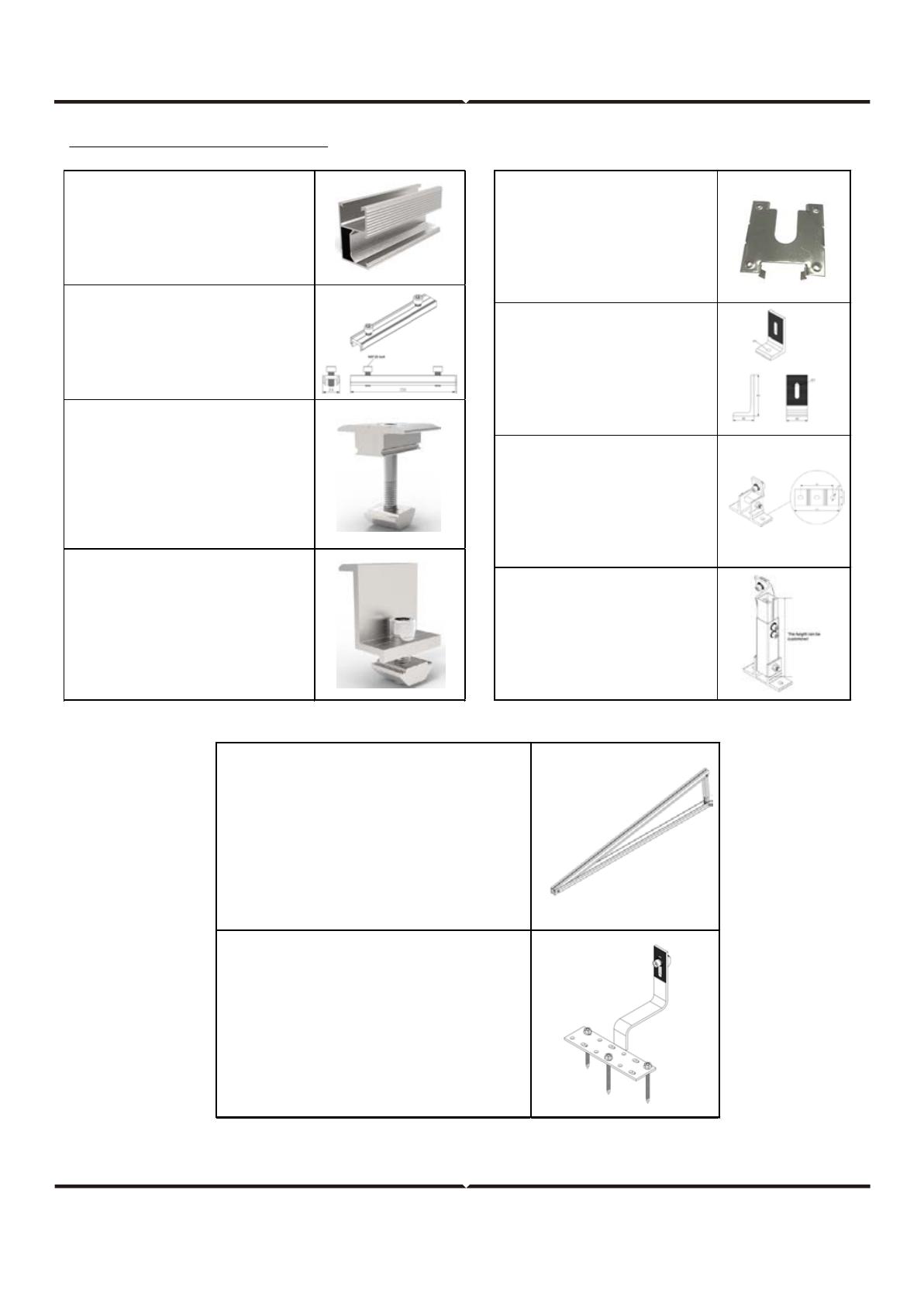
Sliver Rail
Holds each panel row.
Length can be customized.
6005-T5 extruded aluminum.
Splice for SR Rail
Extend SR Rail to any length as required
by the quantity or width of the solar
panels.
Include M8*20 bolts (2Pcs).
Middle Clamp Kit
Fit between two panels
Fastened with a 6mm Allen key
Standard pre-assembly for the usual
panels
Include M8 bolt (1Pc), M8 spring
washer (1Pc), and Nut (1Pc)
End Clamp Kit
Hold the edge of each end panels
Fastened with a 6mm Allen key
Standard pre-assembly for the usual
panels
Include M8*25 bolt (1Pc), M8 spring
washer (1Pc), and Nut (1Pc)
Grounding Clip
Electric Conduction
Material: Stainless steel
L Feet Group
Include M8*25 bolt (1Pc), M8 spring
washer (1Pc), Flange washer (1Pc),
and Nut (1Pc)
Adjustable Front Leg
Include M8*25 bolt (1Pc), M8 spring
washer (1Pc), M8 flange washers (1Pc),
M8*55 bolt (1Pc), flange nut with M8
locking (1Pc), and Nut (1Pc)
Teeth
Adjustable Rear Leg
Include M8*25 bolt (1Pc), M8 spring
washer (1Pc), M8 flange washers (2Pcs)
,
Nut (1Pc), M8*55 bolt (1Pc), flange nuts
with M8 locking teeth (4Pcs), M8*20 bolt
(1Pc), and M8*15 bolt (1Pc)
Adjustable Triangle Support
Include M8*50 bolts (3Pcs), M8 spring
washers (3Pcs), flat washers (3Pcs),
M8 nuts (3Pcs), and st6.3*25 screw (1Pc)
The size can be Customized
Hook Group
Include M8*25 bolt (1Pc), M8 spring
washer (1Pc), M8 flange washers (2Pcs),
nut (1Pc), and st6.3*50 screw (3Pcs)
The best way to identify the type of concealed roof installed is to check the label normally located underneath the roong sheet.
Otherwise, you can contact the builder or check the building plan to nd out the exact type of the roong sheet.
Diagram below, the distances between roof connections for a portrait installation are specied. Clamp on roof hooks need to be
installed in specic distances, depending on the distance of rafters and the stoical conditions.
Height of the module eld: module height x number of modules vertically
Width of the module eld: number of modules horizontally x (width of the module + 20 mm)+80 mm
Distance between roof connections vertically (according to the clamping points pre-dened by the module producer):
Quarter-points of the modules, about 1/2 of module height.
Distance between roof connections horizontally: Depending on the distance between rafters and on the
static requirements .
Distance between modules: 20 mm
When positioning the modules, please take into consideration
That the values above are
That dimensions of roof covering and the position of the rafters dene the precise actual horizontal distance between roof connec-
tions
That the distance between roof laths denes the precise actual vertical distance between roof connections.
DETERMINE THE TYPE OF CONCEALED ROOF
DESIGNING THE MODULE FIELD
3 WAYS OF INSTALLATION
INSTALL ON TILE ROOF
1. Install Hook
First determine the distance between rafters and
on the static requirements, then fasten the hook
with st6.3*50 screw.
2. Install SR Rail
a. Insert the TT-Nut into the side channel of the
SR rail C1 C2
b. Adjust the SR Rail to be level, then fasten the
bolt.
c. First put the TT Rail Splice into the side channel
of the SR Rail about 75mm, then fasten the M8
Bolt. Finally put the other SR Rail into the C3 C4
other side of the SR Rail Splice and fasten the
other M8 bolt.
d. Safety Torque: 20 N.m
3. Install modules
a. Fixing the outer modules by End clamp kit
b. Fixing the inter modules by middle clamp kit
c. Fasten the bolts
d. Safety Torque: 20 N.m
4.Finshed
INSTALL ADJUSTABLE FRONT AND
REAR LEG MOUNTING SYSTEM
a. First of all, please confirm the installation site
and select the appropriate screws to fix the front
and rear leg. For example, it’s best to use
st6.3*50 for metal sheet.
b. According to the design drawing, install the
2. Install SR rail
a. Insert the TT-Nut into the side channel of the
SR rail
b. Adjust the SR Rail to be level, then fasten the
bolt.
of the SR Rail about 75mm, then fasten the M8
Bolt. Finally put the other SR Rail into the other
side of the SR Rail Splice and fasten the other M8
bolt.
c. Safety Torque: 20 N.m
INSTALL ADJUSTABLE TRIANGLE
SUPPORT MOUNTING SYSTEM
3. Install modules
a. Fixing the outer modules by End clamp kit
b. Fixing the inter modules by middle clamp kit
c. Fasten the bolts
Safety Torque: 20 N.m
4. Finished
1. Install Triangle Support
a. Open the triangle support, fix it in the position
of the design drawing, and fasten the all bolts.
b. Safety Torque: 20 N.m
2. Install L Feet Group
a. First slide the bolt in along the groove of the
inclined beam of triangle support, and then
rotate the T-bolt perpendicular to it. Finally
install l feet group, and fasten the bolt. Refer to
a1 a2
the four steps on the right.
b. Safety Torque: 20 N.m
3. Install SR Rail
a. Insert the TT-Nut into the side channel of the
SR rail C1 C2
b. Adjust the SR Rail to be level, then fasten the
bolt.
c. First put the TT Rail Splice into the side channel
of the SR Rail about 75mm, then fasten the M8
Bolt. Finally put the other SR Rail into the other
side of the SR Rail Splice and fasten the other M8
bolt.
a. Safety Torque: 20 N.m
4. Install modules
a. Fixing the outer modules by End clamp kit
b. Fixing the inter modules by middle clamp kit
c. Fasten the bolts
Safety Torque: 20 N.m
5. Finshed
CABLE TIE AND GROUNDING
Tie cable with the rail using the zip �e
Solar groundin system installa�on guide.
  • Page 1 1
  • Page 2 2
  • Page 3 3
  • Page 4 4
  • Page 5 5
  • Page 6 6
  • Page 7 7
  • Page 8 8
  • Page 9 9
  • Page 10 10

V TAC V-TAC Solar Roof Mounting System Installation guide

Type
Installation guide

Ask a question and I''ll find the answer in the document

Finding information in a document is now easier with AI