Installation
Read ‘Safety information’ before installing the fixture.
The fixture is designed for indoor use only and must be used in a dry location with adequate
ventilation. Ensure that none of the fixture’s ventilation slots are blocked.
Fasten the fixture to a secure structure or surface. Do not stand it on a surface or leave it
where it can be moved or fall over. If you install the fixture in a location where it may cause
injury or damage if it falls, secure it as directed in this user manual using a securely anchored
safety cable that will hold the fixture if the primary fastening method fails.
Fastening the fixture to a flat surface
The fixture can be fastened to a hard, fixed, flat surface that is oriented at any angle. Ensure
that the surface and all fasteners used can support at least 10 times the weight of all fixtures
and equipment to be installed on it.
Fasten the fixture securely. Do not stand it on a surface or leave it where it can be moved or
fall over. If you install the fixture in a location where it may cause injury or damage if it falls,
secure it as directed below with a securely anchored safety cable that will hold the fixture if
the primary fastening method fails.
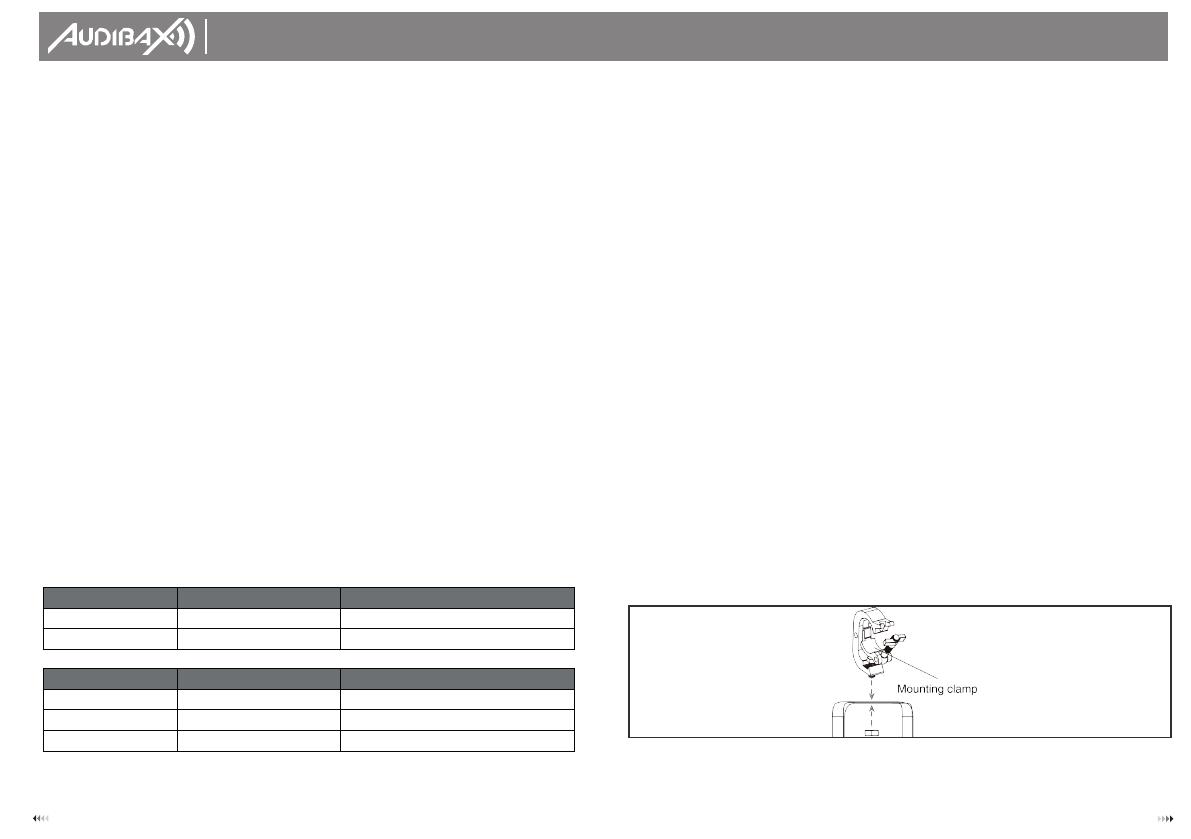
Mounting the fixture on a truss
The fixture can be clamped to a truss or similar rigging structure in any orientation. When
installing the fixture hanging vertically down, you can use an open-type clamp such as a
G-clamp. When installing in any other orientation, you must use a half-coupler clamp that
completely encircles the truss chord.
To clamp the fixture to a truss:
1. Check that the rigging structure can support at least 10 times the weight of all fixtures and
equipment to be installed on it.
2. Block access under the work area.
3. Fold the legs of the mounting bracket together and bolt a rigging clamp securely to the
mounting bracket. The bolt used must be M10, grade 8.8 steel minimum. It must pass through
both mounting bracket legs and be fastened with a self-locking nut.
4. Working from a stable platform, hang the fixture with its clamp on the truss and fasten the
clamp securely.
5. Secure the fixture with a safety cable as directed below.
USER´S
MANUAL
Joliet 100 Zoom
7 4
If you set the same address, all the units will start to listen to the same control signal from the
same channel number. In other words, changing the settings of one channel will affect all
the fixtures simultaneously.
If you set a different address, each unit will start to listen to the channel number you have
set, based on the quantity of control channels of the unit. That means changing the settings
of one channel will affect only the selected fixture.
In the case of the Joliet 100 Zoom, which is 2/3/4/5 channels fixture. If you set, for example,
the ad- dress in the 2 channel mode to channel 3, the device will use the channel 3 to 4 for
control.
Universal DMX Control
This function allows you to use a universal DMX-512 controller to control the dimmer and
strobe. A DMX controller allows you to create unique programs tailored to your individual
needs.
RDM control
The Joliet 100 Zoom can communicate using RDM (Remote Device Management) in
accordance with ESTA’s American National Standard E1.20-2006: Entertainment Technology
RDM Remote Device Management over DMX512 Networks.
RDM is a bi-directional communications protocol for use in DMX512 control systems; it is the
open standard for DMX512 device configuration and status monitoring.
The RDM protocol allows data packets to be inserted into a DMX512 data stream without
affecting existing non-RDM equipment. It allows a console or dedicated RDM controller to
send commands to and receive messages from specific fixtures.
With RDM function, you can set the DMX address of your fixtures remotely. This is especially
useful when the device is installed in a remote area.
Each Joliet 100 Zoom has a factory set RDM UID (unique identification number).
DMX Protocol
2 Channels Mode Function Function Control
CH1 Dimmer
00-255: 0-100% dimmer
CH2 Zoom
00-255: zoom function
CH1 Dimmer
00-255: 0-100% dimmer
CH2 Strobe
00-255: strobe with speed increasing
CH3 Zoom
00-255: zoom function