
1) Desconecte la corriente.
2) Sujete la plancha para montar a la caja de conexión. (No se
proveen los tornillos).
3) Inserte el tube roscado en la plancha para montar.
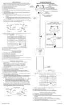
4) Instrucciones de puesta a tierra: (Vea la ilustración A o B)
A) En los artefactos donde se proporciona la abrazadera de monta-
je con un agujero y dos depresiones elevadas. Envuelva el alam-
bre a tierra de la caja de salida alrededor del tornillo a tierra
verde y rosque el tornillo en el agujero.
B) En los artefactor donde se proporciona una arandela cóncava.
Ponga el alambre a tierra de la caja de salida entre la arandela
cóncava y el tornillo a tierra verde y rosque el tornillo en el agu-
jero, en la abrazadera de montaje.
Si se proporciona el artefacto con alambre a tierra, conecte el
alambre a tierra del artefacto al alambre a tierra de la caja de sal-
ida, con el conector de alambre (no proporcionado), después de
seguir los pasos de arriba.
Nunca conecte el alambre a tierra a los alambres blanco o negro
de la alimentación eléctrica.
5) Hacer las conexiones de los alambres (conectores no incluidos).
Ver el cuadro más abajo para las conexiones correctas y alambrar
de acuerdo a esto.
6) Empuje la unidad contra la pared, pasando con cuidado el tube
roscado a través del agujero.
7) Sujete la unidad contra la pared apretándola con la tapa roscada.
INSTRUCCIONES PARA INSTALAR LA UNIDAD EN EL EXTERIOR
YO EN LUGARE HUMEDOS
8) La superficie donde se monta la unidad debe ser limpia, seca, plana
y
1
/
4
” más grande que el escudete en todos los lados. Cualquier
abertura mayor de
3
/
16
” entre la superficie y el escudete, debe ser
corregida como se requiera.
9) Con la pasta de silice, masille completamente al rededor, donde el
escudete toca la superficie de la pared, para evitar que el aqua pen-
etre a la caja de conexión.
10) Inserte la bombilla recomendada.
11) Monte al artefacto la varilla doblada en U en la parte inferior.
Deslice un extremo de la varilla en el agujero en el artefacto, luego
oprima la varilla hasta que el otro extremo se deslice en el agujero.
12) Monte la varilla restante al artefacto de la misma manera que la
primera. La segunda varilla se desliza en la varilla doblada en U en
la primera varilla.
Date Issued 5/26/95
IS-9022-US
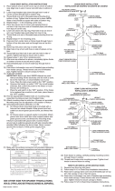
1) Turn off power.
2) Attach mounting strap to outlet box. (Screws not provided)
3) Thread hexnut onto threaded pipe so that 5 threads are exposed
above hexnut. Thread that end of the threaded pipe into mounting
strap and tighten hexnut against mounting strap.
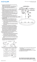
4) Grounding instruction: (See Illus. A or B)
A) On fixtures where mounting strap is provided with a hole and
two raised dimples. Wrap ground wire from outlet box around
green ground screw and thread screw into hole.
B) On fixtures where cupped washer is provided. Put ground wire
from outlet box between cupped washer and green ground
screw and thread screw into hole in mounting strap.
If fixture is provided with ground wire, connect fixture ground
wire to outlet box ground wire with wire connector (Not pro-
vided), after following the above steps.
Never connect ground wire to white or black power supply
wires.
5) Make wire connections (connectors not provided.) Reference chart
below for correct connections and wire accordingly
6) Push fixture to wall, carefully passing threaded pipe through hole.
7) Tighten fixture to wall with threaded cap.
INSTRUCTIONS FOR MOUNTING FIXTURE OUTDOORS AND / OR
IN WET LOCATION
8) Mounting surface should be clean, dry, flat and
1
/
4
” larger than the
canopy on all sides. Any gaps between the mounting surface and
canopy exceeding
3
/
16
” should be corrected as required.
9) With silicone caulking compound, caulk completely around where
back of canopy meets the wall surface to prevent water from seep-
ing into outlet box.
10) Insert recommended bulb.
11) Assemble rod with U-bend in bottom to fixture first. Slip one end of
rod into hole in fixture then squeeze rod until other end will slip into
hole.
12) Assemble remaining rod to fixture in same manner as first. Second
rod slips into U-bend in first rod.
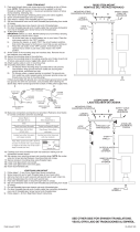
MOUNTING SCREW
TORNILLO DE MONTAJE
FIXTURE
ARTEFACTO
U-BEND
RACCORD EN U
FIRST ROD
PREMIERE TIGE
SECOND ROD
DEUXIEME TIGE
MOUNTING STRAP
ABRAZADERA DE MONTAJE
Connect Black or
Red Supply Wire to:
Connect
White Supply Wire to:
Black White
*Parallel cord (round & smooth) *Parallel cord (square & ridged)
Clear, Brown, Gold or Black
without tracer
Clear, Brown, Gold or Black
with tracer
Insulated wire (other than green)
with copper conductor
Insulated wire (other than green)
with silver conductor
*Note: When parallel wires (SPT I & SPT II)
are used. The neutral wire is square shaped
or ridged and the other wire will be round in
shape or smooth (see illus.)
Neutral Wire
Conectar el alambre de
suministro negro o rojo al
Conectar el alambre de
suministro blanco al
Negro Blanco
*Cordon paralelo (redondo y liso)
*Cordon paralelo (cuadrado y estriado)
Claro, marrón, amarillio o negro
sin hebra identificadora
Claro, marrón, amarillio o negro
con hebra identificadora
Alambre aislado (diferente del verde)
con conductor de cobre
Alambre aislado (diferente del
verde) con conductor de plata
*Nota: Cuando se utiliza alambre paralelo
(SPT I y SPT II). El alambre neutro es de forma
cuadrada o estriada y el otro alambre será de
forma redonda o lisa. (Vea la ilustracíón).
Hilo Neutral
SILICONE CAULKING
CALAFATEO DE SILICONA
GREEN GROUND
SCREW
CUPPED
WASHER
A
B
OUTLET BOX
GROUND
FIXTURE
GROUND
DIMPLES
WIRE CONNECTOR
(NOT PROVIDED)
OUTLET BOX
GROUND
GREEN GROUND
SCREW
FIXTURE
GROUND
ARANDELA
CONCAVA
A
B
TIERRA DE LA
CAJA DE SALIDA
TORNILLO DE TIERRA,
VERDE
DEPRESIONES
TIERRA
ARTEFACTO
CONECTOR DE ALAMBRE
(NO SE PROVEE)
TIERRA DE LA
CAJA DE SALIDA
TORNILLO DE TIERRA,
VERDE
TIERRA
ARTEFACTO
OUTLET BOX
CAJA DEL
TOMACORRIENTE
THREADED CAP
TAPA ROSCADO
THREADED PIPE
TUBO ROSCADO
-
 1
1
Ask a question and I''ll find the answer in the document
Finding information in a document is now easier with AI
in other languages
- español: Kichler 9022BK Manual de usuario
Related papers
Other documents
-
 Kichler Lighting 42565BK User manual
-
 Kichler Lighting 43191AUB User manual
-
 Kichler Lighting 42547CLP User manual
-
 Kichler Lighting 43185AUB User manual
-
 Kichler Lighting 42432AP User manual
-
 Kichler Lighting 42566BK User manual
-
 Kichler Lighting 42591BK User manual
-
 Kichler Lighting 42436AP User manual
-
 Kichler Lighting 42568BK User manual
-
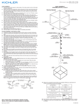 Kichler Lighting 42525OZ User manual


