Digital View AC-1024v3 Owner's manual
- Category
- TVs & monitors
- Type
- Owner's manual

1
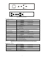
ANALOG INTERFACE CONTROLLER
FOR 1024 x 768 RESOLUTION TFT LCD
Model: AC-1024 V.3
Part number: 4163400-0X
Part number: 4163400-3X
INSTRUCTIONS
CONTENTS
Page: 2. Introduction, How to Proceed, Usage Note, Disclaimer
2. Quick Guide
3. System design – Diagram of a suggested system
4. Assembly notes – Important information about system elements
6. Connection & Operation – How to use the controller
10. Connectors, pinouts & jumpers – Essential connection information
16. Controller dimensions
17. Application notes
18. Troubleshooting
19. Specifications
20. Warranty, Caution & Limitation of Liability, Trademarks
21. Contact details
It is essential that these instructions are read and understood before connecting or
powering up this controller.

2
Introduction
Designed for LCD monitor and other flat panel display applications the AC-1024 V.3 controller provides an auto-input
synchronization and easy to use interface controller for:
Ø TFT (active matrix) LCD’s of 1024 x 768, 800x600, 640x480 resolution;
Ø Computer video signals of VGA, SVGA & XGA standard;
Ø Video signals of PAL & NTSC standard (optional add-on board required);
Ø Volume control of audio (optional add-on board required);
Ø Mirror image (vertical & horizontal) options for the best direction of viewing.
HOW TO PROCEED
• Ensure you have all parts & that they are correct, refer to:
• Connection diagram (separate document for each panel)
• Connector reference (in following section)
• Assembly notes
• Check controller switch & jumper settings (errors may damage the panel)
• Prepare the PC
• Connect the parts
• Understand the operation & functions
IMPORTANT USAGE NOTE
This equipment is for use by developers and integrators, the manufacturer accepts no liability for damage or injury
caused by the use of this product. It is the responsibility of the developer, integrators or other user of this product to:
• Ensure that all necessary and appropriate safety measures are taken.
• Obtain suitable regulatory approvals as may be required.
• Check power settings to all component parts before connection.
DISCLAIMER
There is no implied or expressed warranty regarding this material.
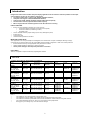
Quick Guide
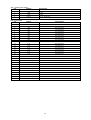
Controller setup table for Normal Version: 4163400-0X
Settings Accessories
Panel Panel power
JP7, JP12 Dip switch
SW1 & SW2 Inverter (note 1)
JP2, JP3
Panel
Connection Inverter Control kit
Hitachi
TX38D12VC0CAA
15”, 1024x768
4x CCFT, 18-bit
JP7: 2-3
JP12: open SW1: Off, On, Off, Off
SW2: Off, Off, Off, Off JP2: 2-3
JP3: 1-2 426470000 Hitachi
PH-BLC36 420680260
410680550 or
410680511
LG (Lucky Goldstar)
LM151X2
15.1”, 1024x768
2x CCFT, 18-bit
JP7: 1-2
JP12: open SW1: Off, On, Off, Off
SW2: On, Off, Off, Off JP2: 2-3
JP3: 1-2 426311401 SI-8390D-02 420680260
410680550 or
410680511
Samsung
LT150X1-151
15”, 1024x768
4x CCFT, 18-bit
JP7: 2-3
JP12: open SW1: Off, On, Off, On
SW2: Off, Off, Off, Off JP2: 2-3
JP3: 1-2 420687550 Samsung
SIC-141 420680260
410680550 or
410680511
Sharp
LQ14X03
13.8”, 1024x768
2x CCFT, 18-bit
JP7: 2-3
JP12: open SW1: Off, On, Off, On
SW2: On, Off, Off, Off JP2: 2-3
JP3: 1-2 410688102
420687452
420687512
SI-8390D-02 420680260
410680550 or
410680511
LQ15X01
15”, 1024x768
2x CCFT, 18-bit
JP7: 2-3
JP12: open SW1: Off, On, Off, On
SW2: On, Off, Off, Off JP2: 2-3
JP3: 1-2 410688102
420687452
420687512
SI-8390D-02 420680260
410680550 or
410680511
Note 1
•The setting for JP2 & JP3 depends on the inverter used.
•The suggest JP2 & JP3 settings only suitable for the mentioned inverter in the table.
•The user has to read the specification of the inverter and find the control method if using other inverter.
•The control information for the AC-1024 V.3 can be found on the jumper table.
•Wrong JP2 & JP3 settings may cause the inverter damage.

3
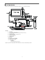
SYSTEM DESIGN
A typical LCD based display system utilising this controller is likely to comprise the following:
Summary:
1. LCD panel
2. LCD controller card, AC-1024 V.3
3. LCD panel connector board for LCD signal cable (if necessary)
4. LCD signal cables
5. Inverter for backlight (if not built into LCD)
6. Inverter power cable
7. Function controls cable
8. Function controls
9. Status LED
10. IR sensor
11. Video add-on board (optional)
12. Audio add-on board (optional)
13. External type VGA cable
- AV cables
- Power supply
-Enclosure or Mounting (not shown).
Digital View provides a range of parts, such as listed above, to make up complete display solutions.

4
ASSEMBLY NOTES
This controller is designed for monitor and custom display projects using 1024 x 768 resolution TFT panels with a VGA, SVGA
or XGA signal input. The following provides some guidelines for installation and preparation of a finished display solution.
Preparation: Before proceeding it is important to familiarize yourself with the parts making up the system and the various
connectors, mounting holes and general layout of the controller. As much as possible connectors have been labeled. Guides to
connectors and mounting holes are shown in the following relevant sections.
1. LCD Panel: This controller is for TFT panels with 5V or 3.3V TTL or LVDS interface. For LVDS a separate add-on board
is required. Due to the variation between manufacturers panels signal timing and other panel characteristics, factory setup
and confirmation should be obtained before connecting to a panel. NOTE: Check panel power jumper settings before
connection)
2. Controller: Handle the controller with care as static charge may damage electronic components. Make sure correct
jumper and dip switches settings to match the target LCD panel.
3. LCD connector board: Different makes and models of LCD panel require different panel signal connectors and different
pin assignments.
WIRING NOTE: If panels of less than 3 x 8 bit are used, eg 3 x 6 bit, then connection of panel signal high value should
correspond to the controllers highest bit. For example for a 6 bit panel R5 on the panel should connect to R7 on the
controller, in this case R1 & R0 on the controller will not be connected.
4. LCD signal cables: In order to provide a clean signal it is recommended that LCD signal cables are no longer than 33cm
(13 inches). If loose wire cabling is utilised these can be made into a harness with cable ties. Care should be taken when
placing the cables to avoid signal interference. Additionally it may be necessary in some systems to add ferrite cores to
the cables to minimise signal noise.
5. Inverter: This will be required for the backlight of an LCD, some LCD panels have an inverter built in. As panels may
have 1 or more backlight tubes and the power requirements for different panel backlights may vary it is important to
match the inverter in order to obtain optimum performance. See Application notes for more information on connection.
6. Inverter Cables: Different inverter models require different cables and different pin assignment. Make sure correct cable
pin out to match inverter. Using wrong cable pin out may damage the inverter.
7. Function controls cable: The cables to the function switches should be of suitable quality and length so that impedance
does not affect performance. Generally lengths up to 1 meter (3 feet) should be acceptable.
8. Function Controls: The following section discusses the controls required and the section on connectors provides the
detail. The controls are minimal: On/Off, Backlight Brightness (depends on inverter), OSD (5 momentary buttons) analog
VR type or (8 momentary buttons) digital type.
9. Status LED: The pin direction of the LED should be corrected for right colour indication. Red colour stands for standby.
Green colours stands for signal on. The status LED is an optional part only, can be unconnected.
10. IR sensor: It is an optional part only, can be unconnected if not using IR remote control.
11. Video input: With the optional video input board added it is possible to accept and display PAL & NTSC signals with
either S-video or composite signal. When the video add-on board is fitted OSD menu functions will be available for
setting video characteristics and controlling the input source. The add-on board also provides RCA type connectors for
audio input (see next note).
12. Audio control: With the optional audio add-on board it is possible to control volume through the OSD menu. The audio
board fits on the right hand edge of the main controller.
13. VGA Input Cable: As this may affect regulatory emission test results and the quality of the signal to the controller a
suitably shielded cable should be utilised.
•• Power Input: 12V DC is required, this should be a regulated supply. Although the controller provides power regulation for
the LCD power this does not relate to the power supplied to the backlight inverter. If an unregulated power supply is
provided to an inverter any fluctuations in power may affect operation, performance and lifetime of the inverter and or
backlight tubes.
•• Power output: Note the controller has an overall 3Amp current limit and the current available from the auxiliary power
output will be dependent on the power input and other system requirements.
•• Power Safety: Note that although only 12VDC is required as ‘power-in’ a backlight inverter for panel backlighting
produces significantly higher voltages (the inverter does not connect to the ground plane). We strongly advise
appropriate insulation for all circuitry.
•• EMI: Shielding will be required for passing certain regulatory emissions tests. Also the choice of external Controller to PC
signal cable can affect the result.
•• Ground: The various PCB mounting holes are connected to the ground plane.

5
•• Servicing: The board is not user serviceable or repairable. Warranty does not cover user error in connecting up to the
controller and is invalidated by unauthorized modification or repairs.
•• Controller Mounting: It is recommended that a clearance of at least 10mm is provided above and 5mm below the
controller when mounted. Additionally consideration should be given to:
•Electrical insulation.
•Grounding.
•EMI shielding.
•Cable management. Note: It is important to keep panel signal cables apart from the inverter & backlight
cables to prevent signal interference.
•Heat & Ventilation: Heat generated from other sources, for example the backlight of a very high brightness
panel may generate significant heat which could adversely affect the controller.
•Other issues that may affect safety or performance.
•• Touch Panels: Support for touch panels or other low power consumption accessories is available by:
•Connector CN1 provides 5V & 12V DC which can be used to power such accessories subject to a maximum
loading recommended at 500mA.
•• PC Graphics Output: A few guidelines:
•Signal quality is very important, if there is noise or instability in the PC graphics output this may result in
visible noise on the display.
•Refer to graphics modes table in specifications section for supported modes.
•Non-interlaced & interlaced video input is acceptable.
IMPORTANT: Please read the Application Notes section for more information.

6
CONNECTION & OPERATION
CAUTION: Never connect or disconnect parts of the display system when the system is powered up as this may cause serious
damage.
CONNECTION
Connection and usage is quite straight forward (it is useful to have the relevant connection diagram available at this time):
1. LCD panel & Inverter: Connect the inverter (if it is not built-in the panel) to the CCFT lead connector of the LCD
panel.
2. TTL type panels: Plug the signal cables direct to CN2, CN3 and CN4 (CN4 will not be used for 3x6-bit panel) on the
controller board. Plug the other end of cables to the LCD connector board (if connector board is required, otherwise
the signal can be direct plug to the LCD panel connector). Then plug the board connector to the LCD panel
connector.
LVDS/Panelink type panels: A LVDS/Panelink transmitter board is required. Plug the transmitter board to CN2,
CN3 & CN4. Then insert the LCD signal cable with controller end to the connector on the transmitter board. Insert
the panel end of the cable the LCD panel connector.
3. Inverter & Controller: Plug the inverter cable to CN5 and CN1 (if necessary). Plug another end to the connector on
the inverter.
4. Function switch & Controller: Plug the OSD switch mount cable to CN6 on the controller board and another to the
OSD switch mount.
5. LED & Controller: Plug in a 3-way with dual colour LED to connector LED1 on the controller board.
6. IR & Controller: Plug in a 3-way with IR sensor to connector IR1 on the controller board.
7. Jumpers & Switches: Check all jumpers and switches (SW1) are set correctly. Details referring the connection
diagram (a separate document) or the jumpers and switches setting table (in the following section).
8. Jumpers & Inverter & Panel voltage: Particularly pay attention to the settings of JP2, JP3, JP6 (on 4163400-0X
only), JP7 and JP12. JP2 & JP3 are used for inverter control (read inverter specification and information on the
jumper table to define the correct settings). JP6, JP7 & JP12 are used for panel voltage input (read panel
specification and information on the jumper table to define the correct settings).
9. VGA cable & Controller: Plug the VGA cable to the connector P1 on the controller board.
10. Power supply & Controller: Plug the DC 12V power in to the connector P3.
11. Power on: Switch on the controller board and panel by using the OSD switch mount.
The red LED will light up when power on. The LED will change to green when VGA signal on.
General:
• If you are using supplied cables & accessories, ensure they are correct for the model of panel and controller.
• If you are making your own cables & connectors refer carefully to both the panel & inverter specifications and the section
in this manual, “Connectors, Pinouts & Jumpers” to ensure the correct pin to pin wiring.
PC SETTINGS
The controller has been designed to take a very wide range of input signals however to minimize the load on the PC’s graphics
systems we recommend choosing 60Hz vertical refresh rate – this will not cause screen flicker.
OPERATION
Once the system has been connected and switched on there are a number of functions available to adjust the display
image as summarised in the following sections. The settings chosen will be saved for each mode independently.
LCD DISPLAY SYSTEM SETTINGS
NOTE: By way of explanation the following refers to a set of sample buttons that may be obtained as an option. In
addition to power on/off and connection for backlight brightness the controller provides an On Screen Display of certain
functions which are controlled by 5 momentary type buttons (analog VR type) or 8 momentary type buttons (digital type):
Controls Analog VR type Digital type
On/Off – turns controller board power on VR toggle switch On/Off button
Brightness – controls backlight brightness Rotary VR Brightness +/- buttons
Menu – turns OSD menu On or Off (it will auto time
off) Menu button Menu button
Select down – moves the selector to the next
function (down) SEL DN SEL DN
Select up – moves the selector to the previous
function (up) SEL UP SEL UP
+ – increase the setting + +
- – decrease setting - -

7
ON/Off/Brightness
SEL UP
SEL DN
+
-
Menu
Analog VR type function control
Digital type function control
OSD functions – PC input:
Volume (note 1) Increase/decrease sound output volume if Audio board is installed.
Press – or + (- ¢¢¢¢¢¢¢¢ + nn), total: 31 steps
Brightness Increase/decrease panel brightness level.
Press – or + (- ¢¢¢¢¢¢¢¢ + nnn), total: 191 steps
Contrast Increase/decrease panel contrast level.
Press – or + (- ¢¢¢¢¢¢¢¢ + nn), total: 79 steps
Tuning Fine tune the data sampling position (adjust display quality).
Press – or + (- ¢¢¢¢¢¢¢¢ + nn), total: 31 steps
Auto setup Auto setting the display, e.g. positions, image size, tuning, etc.
Press + to activate auto setup.
FRC Frame rate control (increase number of colors on a lower bit panel)
Press – or + (On / Off)
PC or Video Set which input signal (PC or Video) has priority if both are connected and active.
Press – or + (PC / Video)
RGB adjustment 4Shows current RGB setting & Adjust RGB color level of video signal by turn on
submenu
Press + turns on submenu (R: rr G: gg B: bb)
Image vertical position Adjust the image vertical position (up & down)
Press – or + (- ¢¢¢¢¢¢¢¢ + nn), total: 127 steps
Image horizontal position Adjust the image horizontal position (left & right)
Press – or + (- ¢¢¢¢¢¢¢¢ + nn), total: 255 steps
Image size – horizontal Adjust the image horizontal size
Press – or + (- ¢¢¢¢¢¢¢¢ + nnnn), total: 255 steps
Image expansion Adjust vertical image size (ON = 10% expansion)
Press – or + (On / Off)
System info 4Shows current system information and turns on the submenu.
Press + turns on submenu (e.g. Vmode, Hf: hh.hkHz, Vf: vv.vHz)
Exit menu Turn off the OSD menu.
Press + turns off the OSD menu.
Extended menu 4Turn on the extended menu.
Press + turns on the extended menu.
Items marked 4 have sub menus.
Note 1: The Volume option will appear if dip-switch (SW2) position #4 is ON. This option will not appear if
SW2 position #4 is OFF. Restart the board is required after setting of SW1 or SW2 to enable the
setting.
RGB Adjustment – sub menu
Red Adjust the red color level
Press – or + (- ¢¢¢¢¢¢¢¢ + nn), total: 80 steps
Green Adjust the green color level
Press – or + (- ¢¢¢¢¢¢¢¢ + nn), total: 80 steps
Blue Adjust the blue color level
Press – or + (- ¢¢¢¢¢¢¢¢ + nn), total: 80 steps
Reset to default Reset the RGB color level to default.
Press + or – resets to default.
Back to main menu Go back to main menu.
Press + or – returns to main menu.
+
BRIGHTNESSSEL. UP
-
ON/OFF MENU
-+
SEL. DN

8
System Info – sub menu
Display type TFT LCD 1024x768 (or other display modes, e.g. 640x480)
Model Shows the model number of the board, e.g. AC-1024 V.3
BIOS version Shows BIOS version
Run time Shows the accumulated running time of the board since last reset
(nnn Hrs nn Min)
Back to main menu Go back to main menu
Press + or – returns to main menu.
Extended menu
Dos text or graphics (note 1) Set text mode or graphic mode in DOS mode.
Press – or + (Dos Text / Graphics)
Auto power down (note 2) Press – or + (On / Off), select power down option
Direct access 1 Turn on direct access table 1. Press + or – turns on table 1.
Direct access 2 Turn on direct access table 2. Press + or – turns on table 2.
Video system (note 3) Select video system, Auto / NTSC / PAL
Signal level Set input signal level (0.7V or 1.0V)
Exclusive or priority Exclusive: disable “PC or Video” option; Priority: enable “PC or Video” option.
(Exclusive / Priority)
OSD vertical position Move OSD menu vertically.
Press – or + (- ¢¢¢¢¢¢¢¢ + nn), total: 256 steps
OSD horizontal position Move OSD menu horizontally.
Press – or + (- ¢¢¢¢¢¢¢¢ + nn), total: 256 steps
Image Vert. Inverse Vertically inverse the image
Press – or + (On / Off)
Image Hori. Inverse Horizontal inverse the image
Press – or + (On / Off)
Menu time out Set menu time-out period
Press – or + (10 / 20 / 30 / 45 / 60 / cont sec.)
Menu auto save Press – or + (Yes / No)
Language 4Select language display for OSD menu
Press + turns on the submenu (English)
Back to main menu Go back to main menu
Note 1 Appears with PC mode only
Note 2 & 3 Appears with Video mode only
Direct access 1 & 2 – sub menu
Volume Define hot keys as volume increase/decrease
Brightness Define hot keys as brightness level increase/decrease
Contrast Define hot keys as contrast level increase/decrease
Tuning Define hot keys as tuning adjustment
PC or Video Define hot keys as PC or Video select
Video input Define hot keys as video signal select (S-video or composite)
Back to previous menu Go back to previous menu
The direct access table 1 and 2 allow the user to define the hot-keys functions. There are two sets of hot-keys can be
defined. SEL UP/SEL DN keys can be defined in the direct access table 1. The +/- keys can be defined in the direct
access table 2.
The hot-key function can be turned on by any one push of SEL UP/SEL DN or +/- then setting can be started.
Language – sub menu
English Select English display
Italiano Select Italian display
Francais Select French display
Espanol Select Spanish display
Svenska Select Swedish display
Deutsche Select Dutch display
Nederlands Select Netherlands display
Back to previous menu Go back to previous menu

9
OSD functions – Video input:
Volume (note 3) Increase/decrease sound output volume if Audio board is installed.
Press – or + (- ¢¢¢¢¢¢¢¢ + nn), total: 31 steps
Brightness Increase/decrease panel brightness level.
Press – or + (- ¢¢¢¢¢¢¢¢ + nnn), total: 191 steps
Contrast Increase/decrease panel contrast level
Press – or + (- ¢¢¢¢¢¢¢¢ + nn), total: 79 steps
Tuning Fine tune the data sampling position (adjust display quality)
Press – or + (- ¢¢¢¢¢¢¢¢ + nn), total: 31 steps
Auto setup Auto setting the display, e.g. positions, Image size, tuning, etc.
Press + to activate auto setup.
FRC Frame rate control (increase number of colors on a lower bit panel)
Press – or + (On / Off)
PC or Video Set which input signal (PC or Video) has priority if both are connected and active.
Press – or + (PC / Video)
Video input Set which input signal (S-video or composite) has priority if both are connected and
active.
Press – or + (S / Comp Video)
Image vertical position Adjust the image vertical position (up & down)
Press – or + (- ¢¢¢¢¢¢¢¢ + nn), total: 127 steps
Image horizontal position Adjust the image horizontal position (left & right)
Press – or + (- ¢¢¢¢¢¢¢¢ + nn), total: 255 steps
Image size – horizontal Adjust the image horizontal size
Press – or + (- ¢¢¢¢¢¢¢¢ + nnnn), total: 255 steps
Image expansion Adjust vertical image size (ON = 10% expansion)
Press – or + (On / Off)
System info 4Shows current system information and turns on the submenu.
Press + turns on submenu (e.g. Vmode, Hf: hh.hkHz, Vf: vv.vHz)
Exit menu Turn off the OSD menu.
Press + turns off the OSD menu.
Extended menu 4Turn on the extended menu.
Press + turns on the extended menu.
Items marked 4 have sub menus.
Note 3: The Volume option will appear if dip-switch (SW2) position #4 is ON. This option will not appear if
SW2 position #4 is OFF. Restart the board is required after setting of SW1 or SW2 to enable the
setting.
The OSD settings chosen will be stored in memory. The OSD menu can be cleared from the screen by pressing the
menu button otherwise it will automatically clear after a few seconds (time-out period) of non-use.
(Note: Instructions for remote control are not provided as this will depend on the handset provided)
MANUAL & REMOTE CONTROL
The following table shows the comparison of functions available from different controls:
Operation One for All Sony multi remote DV switchmount DV digital VR
switchmount
Menu Power Power Menu Menu
Default Mute Mute - -
Select + Ch+ Ch+ Select Select +
Select - Ch- Ch- Select - Select -
Setting + Vol+ Vol+ Setting + Setting +
Setting - Vol- Vol- Setting - Setting -
Other multi-system IR transmitters will also be suitable if they support common Sony signal timings.
RS-232 serial control
A RS-232 driver chip (e.g. Maxim MAX232A or compatible, 16-pin dip package) needed to installed onto position U20 to
enable the RS-232 linkage. The RS-232 (J2) cable pin out can be found tables in next section. Then OSD function can
be controlled through send HEX code with the following button mapping.
MENU 0xf7
SEL_DN 0xfa
SEL_UP 0xfb
PLUS 0xfc
MINUS 0xfd
To reset the run time counter: While in “SYS INFO” : “RUN TIME”, send in 10 bytes of “0xfc” (plus key) will reset the run
time counter.
To recall the factory default setting: Anytime while the controller is in normal operation, send in 10 bytes of “0xfe” will
recall the factory defaults (it is equivalent to pressing the SEL_DN button during power up).
RS-232 baud rate is 2400 baud.
Please set jumper JP11 for RS-232 voltage level. Details please refer the jumpers table in the following section.

10
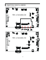
CONNECTORS, PINOUTS & JUMPERS
The various connectors are:
P/N: 4163400-0X
P/N: 4163400-3X

11
Summary: Connectors (Note 24 bit = 3 x 8 bit, 18 bit = 3 x 6 bit)
Ref Purpose Description
CN1 Auxiliary power JST 4-way, B4B-XH-A
CN2 Panel signal Hirose 28 pin, DF11-28DP-2DSA
CN3 Panel signal Hirose 32 pin, DF11-32DP-2DSA
CN4 Panel signal – 8 bit Hirose 20 pin, DF11-20DP-2DSA
CN5 Backlight inverter JST 5-way, B4B-XH-A
CN6 Function controls JST 12-way, B12B-XH-A
CN7 Audio board connector DIL socket header 5x2 right angle
CN8 Reserved Factory use only
CN9 Function controls (alternative) Hirose 15 pin, DF13-15P-1.25DSA
J1 Video add-on connector DIL socket header 13x2
J2 RS-232 linkage Header pin 6x1
IR1 Infra-Red sensor connector JST 3-way, B3B-XH-A
LED Dual color LED connector Header pin 3x1
P1 VGA analog input DB-15 way high density 3 row
P2 VGA input (alternative) Pin header, 8 x 2
P3 Main power input DC power jack, 2.5mm contact pin diameter
P4 Power input (alternative) DC power Molex 2 pin 0.156” pitch
P5 Power input (alternative) DC power Molex 2 pin 0.2” pitch (not normally installed)
Summary: Jumpers setting
Ref Purpose Note
JP1 On board logic power enable 1-2 & 3-4 closed, factory set, do not remove
JP2 Backlight inverter on/off control –
signal level 1-2 = On/Off control signal ‘High’ = +12V
2-3 = On/Off control signal ‘High’ = +5V
Open = On/Off control signal ‘High’ = Open collector
CAUTION: Incorrect setting can damage inverter.
JP3 Backlight inverter on/off control –
polarity 1-2 = control signal ‘high’ = CCFT ON
2-3 = control signal ‘low’ = CCFT ON
JP4~6 Not present
JP7 Panel power voltage select 1-2 = +3.3V supply
2-3 = +5V supply
JP8 Reserved
JP9~10 Not present
JP11 RS-232 signal level select 1-2 & 2-4 = +12V
3-5 & 4-6 = +5V
JP12 +12V panel power voltage select 1-2 = enable +12V safe panel power
Open = disable +12V panel power
JP13
JP14
JP15
Panel clock select
Dose not present on 4163400-0X (JP13: 3-4 & JP14: 1-2 & JP15: 1-2) = XGA panels
(JP13: 3-4 & JP14: 1-2 & JP15: 2-3) = SVGA panels
(JP13: 3-4 & JP14: 1-2 & JP15: open) = VGA panels
SW1 Panel & function selection See table below
SW2 Panel & function selection See table below
SW1 & SW2: Panel and function selection
Pos. # Function Description
SW1-#1 Vertical filter ON = enable; OFF = disable
SW1-#2
SW1-#3
SW1-#4 Panel selection ON, OFF, ON = Dual pixels clock XGA panels
ON, OFF, OFF = Single pixel clock XGA panels
OFF, ON, ON = SVGA panels
OFF, OFF, ON = VGA panels
SW2-#1 Clock phase select Adjust image stability
SW2-#2 Display enable selection ON = generate DE during Sync
OFF = Does not generate DE during Sync
SW2-#3 Vertical stability Adjust image vertical stability for some VGA/SVGA panels
SW2-#4 Volume selection ON = enable
OFF = disable

12
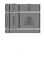
CN1 - Auxiliary power output
PIN SYMBOL DESCRIPTION
1AUX 12V +12V DC, 300mA max
2GND Ground
3GND Ground
4AUX 5V +5V DC, 300mA max
CN2 - To LCD panel
PIN SYMBOL DESCRIPTION
1GND Ground
2GND Ground
3ER2 Even data bit R2
4OR2 Odd data bit R2
5ER3 Even data bit R3
6OR3 Odd data bit R3
7ER4 Even data bit R4
8OR4 Odd data bit R4
9ER5 Even data bit R5
10 OR5 Odd data bit R5
11 EG2 Even data bit G2
12 OG2 Odd data bit G2
13 EG3 Even data bit G3
14 OG3 Odd data bit G3
15 EG4 Even data bit G4
16 OG4 Odd data bit G4
17 EG5 Even data bit G5
18 OG5 Odd data bit G5
19 EB2 Even data bit B2
20 OB2 Odd data bit B2
21 EB3 Even data bit B3
22 OB3 Odd data bit B3
23 EB4 Even data bit B4
24 OB4 Odd data bit B4
25 EB5 Even data bit B5
26 OB5 Odd data bit B5
27 GND Ground
28 GND Ground

13
CN3 - To LCD panel
PIN SYMBOL DESCRIPTION
1+12v DC +12v, reserved & not normally used
2+12v DC +12v, reserved & not normally used
3NC No connection
4NC No connection
5GND Ground
6GND Ground
7ER6 Even data bit R6
8OR6 Odd data bit R6
9ER7 Even data bit R7 (MSB of lower colour bit panels)
10 OR7 Odd data bit R7 (MSB of lower colour bit panels)
11 EG6 Even data bit G6
12 OG6 Odd data bit G6
13 EG7 Even data bit G7 (MSB of lower colour bit panels)
14 OG7 Odd data bit G7 (MSB of lower colour bit panels)
15 EB6 Even data bit B6
16 OB6 Odd data bit B6
17 EB7 Even data bit B7 (MSB of lower colour bit panels)
18 OB7 Odd data bit B7 (MSB of lower colour bit panels)
19 GND Ground
20 GND Ground
21 Vcc DC +5v, reserved & not normally used
22 Vcc DC +5v, reserved & not normally used
23 VS Vertical sync
24 PwrDn Power down control signal (5v TTL)
25 HS Horizontal sync
26 DE Display enable
27 VLCD Panel supply (switched)
28 VLCD Panel supply (switched)
29 CKE Even dot clock (shift clock)
30 CKO Odd dot clock (shift clock)
31 GND Ground
32 GND Ground

14
CN4 - To LCD panel - for 24 bit panels only
PIN SYMBOL DESCRIPTION
1GND Ground
2GND Ground
3NC No connection
4NC No connection
5ER0 Even data bit R0
6OR0 Odd data bit R0
7ER1 Even data bit R1
8OR1 Odd data bit R1
9EG0 Even data bit G0
10 OG0 Odd data bit G0
11 EG1 Even data bit G1
12 OG1 Odd data bit G1
13 EB0 Even data bit B0
14 OB0 Odd data bit B0
15 EB1 Even data bit B1
16 OB1 Odd data bit B1
17 NC No connection
18 NC No connection
19 GND Ground
20 GND Ground
CN5 - To backlight inverter
PIN SYMBOL DESCRIPTION
1GND Ground
2VBKL +12VDC, 1A backlight power supply
3BLCTRL On/Off control (enable) – see JP1, 2 & 3
4BVR_WIP Brightness VR – WIP
5BVR_A Brightness VR A
CN6 - To control switches
PIN SYMBOL DESCRIPTION
1PSWIN Power switch A
2SW_ON Power switch B
3BVR_A Backlight brightness VR pin A
4BVR_WIP Backlight brightness VR pin WIP
5BVR_B Backlight brightness VR pin B (470Ω resistor to +5V Vcc)
6GND Ground
7MENU OSD menu button
8-/LEFT OSD -/Left button
9+/RIGHT OSD +/Right button
10 SEL OSD Select down button
11 SEL_UP OSD Select up button
12 NC No connection
The VR for brightness depends on the inverter.
The main power load for On/Off is handled by a relay on the controller.
CN7 - To Audio add-on board
Inter connection only

15
J2 – Serial control (RS-232), 6-pin header
PIN SYMBOL DESCRIPTION
1SDATA Reserved
2SCLK Reserved
3Vcc +5V
4TXD RS-232 Tx data
5GND Ground
6RXD RS-232 Rx data
P1 & P2 - ANALOG VGA INPUT - 15 way connector
PIN SYMBOL DESCRIPTION
1PCR Red, analog
2PCG Green, analog
3PCB Blue analog
4ID2 Reserved for monitor ID bit 2 (grounded)
5DGND Digital ground
6AGND Analog ground red
7AGND Analog ground green
8AGND Analog ground blue
9DDC_5V +5V power supply for DDC (optional)
10 DGND Digital ground
11 ID0 Reserved for monitor ID bit 0 (grounded)
12 DDC_SDA DDC serial data
13 HS_IN Horizontal sync or composite sync, input
14 VS_IN Vertical sync, input
15 DDC_SCL DDC serial clock
P3, P4 & P5 - 12VDC power supply - input
PIN DESCRIPTION
1+12VDC in middle pin, 2A (1.85A main auto-reset fuse protected)
2Ground

16
CONTROLLER DIMENSIONS
The maximum thickness of the controller is 23mm with or without video add-on board (measured from bottom of
PCB to top of components, including any underside components & leads). We recommend clearances of:
•5mm from bottom of PCB - if mounting on a metal plate we also recommend a layer of suitable insulation
material is added to the mounting plate surface.
•10mm above the components
•3~5mm around the edges
Any of the holes shown above can be used for mounting the PCB, they are 3.2mm in diameter.
CAUTION: Ensure adequate insulation is provided for all areas of the PCB with special attention to high
voltage parts such as the inverter.

17
APPLICATION NOTES
USING THE CONTROLLER WITHOUT BUTTONS ATTACHED
This is very straightforward:
•Firstly setup the controller/display system with the buttons. With controls attached and display system active make
any settings for colour, tint and image position as required then switch everything off.
•Remove the control switches, the 12-way (CN6) cable.
•Use a jumper or similar to connect pins 1 & 2 on CN6, this will fix the board On.
•Refer to inverter specifications for details as to fixing brightness to a desired level, this may require a resistor, an
open circuit or closed circuit depending on inverter.
Summary: On CN6 the only pins that are used are for On/Off and Brightness (if controller mounted inverter is used). On CN6
the pins are for momentary type buttons so it doesn’t matter that no buttons are attached.
INVERTER CONNECTION
There are potentially 3 issues to consider with inverter connection:
•Power
•Enable
•Brightness
Please read the following sections for a guide to these issues.
Inverter Power: As per the table for CN5 pin 1 is ground and pin 2 provides 12V DC. This should be matched with the inverter
specification: see table.
CN5
PIN DESCRIPTION
1Ground
2+12VDC
Enable: This is a pin provided on some inverters for On/Off function and is used by this panel controller for VESA DPMS
compliance. If the inverter does not have an enable pin or the enable pin is not used then DPMS will not be operational. Pin 3
should be matched to the inverters specification for the ‘enable’ or ‘disable’ pin.
CN5
PIN DESCRIPTION
3Enable
Further, jumpers 2 & 3 should be set to match the inverters specification for the enable pin power and High or Low setting: see
table.
Ref Purpose Note
JP2 Inverter enable voltage 1-2 H = 12V, 2-3 H = 5V (Vcc), OPEN H = open collector
JP3 Inverter control 1-2 H = On, 2-3 L = On
Brightness: There are various methods for brightness control and it is important to consider the specifications for the inverter
to be used. Generally the situation is:
•Brightness can controlled by using a resistor or VR (Variable Resistor).
•Brightness controlled by adding a circuit such as PWM (Pulse Width Modulation).
•No adjustment of brightness is possible.
CN5 pins 4 & 5 are available for connecting to an inverter or circuit where VR control is supported.
CN5
PIN DESCRIPTION
4VR WIP
5VR A
This can then be matched with function controls connected to CN6 pins 4 & 3 or 5: see table.
CN6
PIN DESCRIPTION
3VR A
4VR WIP
5VR B

18
TROUBLESHOOTING
General
A general guide to troubleshooting a flat panel display system it is worth considering the system as separate elements, such
as:
• Controller (jumpers, PC settings)
• Panel (controller, cabling, connection, panel, PC settings)
• Backlight (inverter, cabling, backlight tubes)
• Cabling
• Computer system (display settings, operating system)
Through step by step cross checking with instruction manuals and a process of elimination to isolate the problem it is usually
possible to clearly identify the problem area.
No image:
•If the panel backlight is not working it may still be possible to just see some image on the display.
•A lack of image is most likely to be caused by incorrect connection, lack of power, failure to provide a signal or
incorrect graphic card settings.
Image position:
•If it is impossible to position the image correctly, ie the image adjustment controls will not move the image far
enough, then test using another graphics card. This situation can occur with a custom graphics card that is not close
to standard timings or if something is in the graphics line that may be affecting the signal such as a signal splitter
(please note that normally a signal splitter will not have any adverse effect).
Image appearance:
•A faulty panel can have blank lines, failed sections, flickering or flashing display
•Incorrect graphics card refresh rate, resolution or interlaced mode will probably cause the image to be the wrong
size, to scroll, flicker badly or possibly even no image.
•Incorrect jumper settings on the controller may cause everything from total failure to incorrect image. CAUTION: Do
not set the panel power input incorrectly.
•Sparkling on the display: faulty panel signal cable.
Backlight:
Items to check include: Power input, Controls, Inverter and Tubes generally in this order.
If half the screen is dimmer than the other half:
• Check cabling for the inverter.
• For a specific backlight tube check the AC pins orientation (CAUTION: Never reverse any DC power pins).
Also:
• If adjusting brightness control has no effect the chances are that the VR rating or method of adjusting brightness is not
compatible or correctly connected to the inverter.
• If system does not power down when there is a loss of signal
Continued failure:
•If unit after unit keeps failing consider and investigate whether you are short circuiting the equipment or doing
something else seriously wrong.
Generally after common sense issues have been resolved we recommend step by step substitution of known working parts to
isolate the problem.

19
SPECIFICATIONS
Panel compatibility (note1) Compatible with TFT LCD panel with resolution of 1024x768, 800x600
& 640x480 from manufacturers such as Sharp, Toshiba, Hosiden,
Hitachi, LG, Samsung, Fujitsu, NEC, Mitsubishi, IBM or others though
a specified BIOS and some factory adjustment may be required for
individual panel timings.
No. of colours Up to 3 x 8 bit providing 16.7 million colours.
Vertical refresh rate VGA, SVGA, XGA to VESA standards up to 85 Hz
Dot clock (pixel clock) maximum 160MHz
Graphics formats Standard VGA, SVGA, XGA with automatic detection of formats of:
Sync on green
Composite sync
Separate sync
Graphics auto mode detect VGA, SVGA, XGA
Standard input at source VGA analog (15 pin) standard, composite sync & sync on green.
Video inputs (optional video add-on board) System support: PAL 50 Hz, NTSC 60 Hz
Input support: Composite video and S-video
Input voltage: Composite video – typical 1.0Vpp
S-video Luma input – typical 1.0Vpp
S-video Chroma input – typical 150mVpp
Horizontal frequency: PAL – 15.625 kHz ± 400 Hz
NTSC – 15.750 kHz ± 400 Hz
Video voltage gain: 12.0 dB
Supply voltage: 5V
Supply current: 100mA
Controls available • On/Off
• Brightness – inverter
• OSD Menu
• OSD Select up
• OSD Select down
• Setting +
• Setting -
Control interface • Buttons
• Infra red
• RS-232
Settings memory Settings are stored in non volatile memory
Run time monitor Updates at 30 minute intervals
PC Connectivity VGA / SVGA / XGA analog
Controller dimensions 179mm x 114mm (7.05” x 4.5”)
Power consumption 10w approx. (not including panel power consumption)
Power load maximum The controller has an overall 3Amp current limit.
Voltage output for LCD +3.3V DC, +5V DC, +12V DC
Input voltage 12VDC
Power protection Fuse fitted
DC Power handling An on board relay handles the power load for On/Off and power
protection to the LCD.
Storage temperature limits -40oC to +70oC
Operating temperature limits 0oC to +65oC
Note 1 AC-1024 V.3 with part number 4163400-0X supports XGA panels only (SVGA and VGA panels are not
supported). Part number 4163400-3X supports multi-panels, e.g. XGA, SVGA and VGA.
NOTES
Please note the following:
•For specific panel setup a sample of an LCD may be required (this will be returned) and a copy of the full
technical specifications for the panel from the manufacturer.
•Relayout and custom development services are available.

20
WARRANTY
The products are warranted against defects in workmanship and material for a period of one (1) year from the date of purchase
provided no modifications are made to it and it is operated under normal conditions and in compliance with the instruction
manual.
The warranty does not apply to:
•Product that has been installed incorrectly, this specifically includes but is not limited to cases where electrical short
circuit is caused.
•Product that has been altered or repaired except by the manufacturer (or with the manufacturer’s consent).
•Product that has subjected to misuse, accidents, abuse, negligence or unusual stress whether physical or electrical.
•Ordinary wear and tear.
Except for the above express warranties, the manufacturer disclaims all warranties on products furnished hereunder, including
all implied warranties of merchantability and fitness for a particular application or purpose. The stated express warranties are in
lieu of all obligations or liabilities on the part of the manufacturer for damages, including but not limited to special, indirect
consequential damages arising out of or in connection with the use of or performance of the products.
CAUTION
Whilst care has been taken to provide as much detail as possible for use of this product it cannot be relied upon as
an exhaustive source of information. This product is for use by suitably qualified persons who understand the nature
of the work they are doing and are able to take suitable precautions and design and produce a product that is safe
and meets regulatory requirements.
LIMITATION OF LIABILITY
The manufacturer’s liability for damages to customer or others resulting from the use of any product supplied hereunder shall
in no event exceed the purchase price of said product.
TRADEMARKS
The following are trademarks of Digital View Ltd:
• Digital View
• AC-1024 V.3
Page is loading ...
-
 1
1
-
 2
2
-
 3
3
-
 4
4
-
 5
5
-
 6
6
-
 7
7
-
 8
8
-
 9
9
-
 10
10
-
 11
11
-
 12
12
-
 13
13
-
 14
14
-
 15
15
-
 16
16
-
 17
17
-
 18
18
-
 19
19
-
 20
20
-
 21
21


Digital View AC-1024v3 Owner's manual
- Category
- TVs & monitors
- Type
- Owner's manual
Ask a question and I''ll find the answer in the document
Finding information in a document is now easier with AI
Related papers
-
Digital View ACM-1024 Owner's manual
-
-
-
-
-
-
-
-
-
DVS -30RF-2 Owner's manual