
TFT-LCD TELEVISION
LTN1565
LTN1765
SERVICE DIVISION
400 Valley Road, Suite 201
Mount Arlington, NJ 07856
TEL: 1-800-SAMSUNG (1-800-726-7864)
www.samsungusa.com
BN68-00438A-0?
01-FRONT COVER-01_en 2/25/03 9:39 AM Page 1

Warning! Important
Safety Instructions
CAUTION: TO REDUCE THE RISK OF ELECTRIC SHOCK, DO NOT
REMOVE COVER (OR BACK). NO USER SERVICEABLE PARTS INSIDE.
REFER SERVICING TO QUALIFIED SERVICE PERSONNEL.
This symbol indicates high voltage is present inside. It is
dangerous to make any kind of contact with any inside part of
this product.
This symbol alerts you that important literature concerning
operation and maintenance has been included with this product.
Note to CATV system installer: This reminder is provided to call CATV system
installer’s attention to Article 820-40 of the National Electrical Code (Section 54 of
Canadian Electrical Code, Part I), that provides guidelines for proper grounding and,
in particular, specifies that the cable ground shall be connected to the grounding
system of the building as close to the point of cable entry as practical.
Caution: FCC/CSA regulations state that any unauthorized changes or
modifications to this equipment may void the user’s authority to operate it.
Caution: To prevent electric shock, match the wide blade of plug to the
wide slot, and fully insert the plug.
Attention: pour eviter les chocs electriques, introduire la lame le plus large de
la fiche dans la borne correspondante de la prise et pousser jusqu’au fond.
Important: One Federal Court has held that unauthorized recording of copyrighted
TV programs is an infringement of U.S. copyright laws.
Certain Canadian programs may also be copyrighted and any unauthorized recording
in whole or in part may be in violation of these rights.
To prevent damage which may result in fire or electric shock hazard,
do not expose this appliance to rain or moisture.
CAUTION
RISK OF ELECTRIC SHOCK
DO NOT OPEN
02-Inside Front Cover_en 2/25/03 8:25 AM Page 1

1
Thank You for Choosing Samsung
Thank you for choosing Samsung! Your new Samsung TV represents the latest in television technology.
We designed it with easy-to-use on-screen menus and closed captioning capabilities, making it one of the
best products in its class. We are proud to offer you a product that will provide convenient, dependable
service and enjoyment for years to come.
Important Safety Information
Always be careful when using your TV receiver. To reduce the risk of fire, electrical shock, and other
injuries, keep these safety precautions in mind when installing, using, and
maintaining your machine.
• Read all safety and operating instructions before operating your TV.
• Keep the safety and operating instructions for future reference.
• Heed all warnings on the TV receiver and in the operating instructions.
• Follow all operating and use instructions.
• Unplug the TV receiver from the wall outlet before cleaning. Use a damp cloth; do not use liquid or
aerosol cleaners.
• Never add any attachments and/or equipment without approval of the manufacturer.
Such additions can increase the risk of fire, electric shock, or other personal injury.
• Do not use the TV receiver where contact with or immersion in water is a possibility,
such as near bath tubs, sinks, washing machines, swimming pools, etc.
• Do not place the TV on an unstable cart, stand, tripod, bracket, or table
where it can fall. A falling TV can cause serious injury to a child or adult,
and serious damage to the appliance. Use only with a cart, stand, tripod,
bracket, or table recommended by the manufacturer or sold with the TV.
Follow the manufacturer’s instructions when mounting the unit, and use a
mounting accessory recommended by the manufacturer. Move the TV and
cart with care. Quick stops, excessive force, and uneven surfaces can
make the unit and cart unsteady and likely to overturn.
• Provide ventilation for the TV receiver. The unit is designed with slots in
the cabinet for ventilation to protect it from overheating. Do not block these openings with any object,
and do not place the TV receiver on a bed, sofa, rug, or other similar surface. Do not place it near a
radiator or heat register. If you place the TV receiver on a rack or bookcase, ensure that there is
adequate ventilation and that you’ve followed the manufacturer’s instructions for mounting.
• Operate your TV receiver only from the type of power source indicated on the marking label.
If you are not sure of the type of power supplied to your home, consult your appliance dealer or local
power company.
• Use only a grounded or polarized outlet. For your safety, this TV is equipped with a polarized
alternating current line plug having one blade wider than the other. This plug will fit into the power
outlet only one way. If you are unable to insert the plug fully into the outlet, try reversing the plug.
If the plug still does not fit, contact your electrician to replace your outlet.
• Protect the power cord. Power supply cords should be routed so that they won’t be walked on or
pinched by objects placed on or against them. Pay particular attention to cords at plugs, convenience
receptacles, and the point where they exit from the unit.
03-PREFACE_en 2/25/03 8:26 AM Page 1

2
• Unplug the TV from the wall outlet and disconnect the antenna or cable system during a lightning
storm or when left unattended and unused for long periods of time. This will prevent damage to the
unit due to lightning and power-line surges.
• Avoid overhead power lines. An outside antenna system should not be placed in the vicinity of
overhead power lines or other electric light or power circuits or where it can fall into such power
lines or circuits. When installing an outside antenna system, be extremely careful to keep from
touching the power lines or circuits. Contact with such lines can be fatal.
• Do not overload the wall outlet or extension cords. Overloading can result in fire or electric shock.
• Do not insert anything through the openings in the unit, where they can touch dangerous voltage
points or damage parts. Never spill liquid of any kind on the TV.
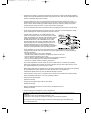
• Ground outdoor antennas. If an outside antenna or cable
system is connected to the TV, be sure the antenna or cable
system is grounded so as to provide some protection against
voltage surges and built-up static charges. Section 810 of
the National Electrical Code, ANSI/NFPA No.70-1984,
provides information about proper grounding of the mast
and supporting structure, grounding of the lead-in wire to
an antenna discharge unit, size of grounding conductors,
location of antenna discharge unit, connection to grounding
electrodes, and requirements for the grounding electrode.
• Do not attempt to service the TV yourself. Refer all servicing to qualified service personnel.
Unplug the unit from the wall outlet and refer servicing to qualified service personnel under the
following conditions:
- when the power-supply cord or plug is damaged
- if liquid has been spilled on the unit or if objects have fallen into the unit
- if the TV has been exposed to rain or water
- if the TV does not operate normally by following the operating instructions
- if the TV has been dropped or the cabinet has been damaged
- when the TV exhibits a distinct change in performance
• If you make adjustments yourself, adjust only those controls that are covered by the operating
instructions. Adjusting other controls may result in damage and will often require extensive work
by a qualified technician to restore the TV to normal.
• When replacement parts are required, be sure the service technician uses replacement parts specified
by the manufacturer or those that have the same characteristics as the original part.
Unauthorized substitutions may result in additional damage to the unit.
• Upon completion of any service or repairs to this TV, ask the service technician to perform safety
checks to determine that the TV is in a safe operating condition.
• Keep all power adaptors apart.
Possible fire hazard.
• Keep the power adaptor away from any other heater.
Possible fire hazard.
• Remove and discard the plastic cover from the power adaptor before use.
Possible fire hazard.
• Always keep the power adaptor in a well-ventilated area.
This device complies with part 15 of the FCC Rules. Operation is subject to the following two
conditions:
(1) This device may not cause harmful interference, and
(2) This device must accept any interference that may cause undesired operation.
This television receiver provides display of television closed captioning in accordance with
§15.119 of the FCC rules.
03-PREFACE_en 2/25/03 8:26 AM Page 2

3
CONTENTS
Chapter 1: Your New TV . . . . . . . . . . . . . . .1.1
List of Features . . . . . . . . . . . . . . . . . . . . . . . . . . . . . . . . . . . . . . . . . . .1.1
Accessories . . . . . . . . . . . . . . . . . . . . . . . . . . . . . . . . . . . . . . . . . . . . . .1.1
Familiarizing Yourself with The TV . . . . . . . . . . . . . . . . . . . . . . . . . . .1.2
Top panel Buttons . . . . . . . . . . . . . . . . . . . . . . . . . . . . . . . . .1.2
Rear Panel Jacks . . . . . . . . . . . . . . . . . . . . . . . . . . . . . . . . . .1.3
Remote Control . . . . . . . . . . . . . . . . . . . . . . . . . . . . . . . . . . .1.4
Chapter 2: Installation . . . . . . . . . . . . . . . . 2.1
Connecting VHF and UHF Antennas . . . . . . . . . . . . . . . . . . . . . . . . . .2.1
Antennas with 300-ohm Flat Twin Leads . . . . . . . . . . . . . . .2.1
Antennas with 75-ohm Round Leads . . . . . . . . . . . . . . . . . .2.2
Separate VHF and UHF Antennas . . . . . . . . . . . . . . . . . . . . .2.2
Connecting Cable TV . . . . . . . . . . . . . . . . . . . . . . . . . . . . . . . . . . . . . .2.2
Cable without a Cable Box . . . . . . . . . . . . . . . . . . . . . . . . . .2.2
Connecting to a Cable Box that Descrambles All Channels .2.3
Connecting to a Cable Box that Descrambles Some Channels
.2.3
Connecting a VCR . . . . . . . . . . . . . . . . . . . . . . . . . . . . . . . . . . . . . . . .2.5
Connecting an S-VHS VCR . . . . . . . . . . . . . . . . . . . . . . . . .2.6
Connecting a DVD Player . . . . . . . . . . . . . . . . . . . . . . . . . . . . . . . . . .2.7
Connecting a Digital TV Set-Top Box . . . . . . . . . . . . . . . . . . . . . . . . .2.7
Connecting a Camcorder . . . . . . . . . . . . . . . . . . . . . . . . . . . . . . . . . . .2.8
Installing Batteries in the Remote Control . . . . . . . . . . . . . . . . . . . . . .2.9
Chapter 3: Operation . . . . . . . . . . . . . . . . . .3.1
Turning the TV On and Off . . . . . . . . . . . . . . . . . . . . . . . . . . . . . . . . .3.1
Viewing the Menus and On-Screen Displays . . . . . . . . . . . . . . . . . . . .3.1
Viewing the Menus . . . . . . . . . . . . . . . . . . . . . . . . . . . . . . . .3.1
Viewing the Display . . . . . . . . . . . . . . . . . . . . . . . . . . . . . . .3.1
Selecting a Menu Language . . . . . . . . . . . . . . . . . . . . . . . . . . . . . . . . .3.2
Memorizing the Channels . . . . . . . . . . . . . . . . . . . . . . . . . . . . . . . . . . .3.3
Selecting the Video Signal-source . . . . . . . . . . . . . . . . . . . . .3.3
Storing Channels in Memory (Automatic Method) . . . . . . . .3.4
Adding and Erasing Channels (Manual Method) . . . . . . . . .3.5
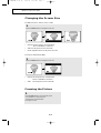
Changing Channels . . . . . . . . . . . . . . . . . . . . . . . . . . . . . . . . . . . . . . . .3.5
Using the Channel Buttons . . . . . . . . . . . . . . . . . . . . . . . . . .3.5
Directly Accessing Channels . . . . . . . . . . . . . . . . . . . . . . . . .3.5
Using the Pre-CH Button to select the Previous Channel . . .3.5
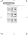
Adjusting the Volume . . . . . . . . . . . . . . . . . . . . . . . . . . . . . . . . . . . . . .3.6
Using Mute . . . . . . . . . . . . . . . . . . . . . . . . . . . . . . . . . . . . . .3.6
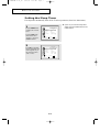
Customizing the Picture . . . . . . . . . . . . . . . . . . . . . . . . . . . . . . . . . . . .3.7
Using Automatic Picture Settings . . . . . . . . . . . . . . . . . . . . . . . . . . . . .3.8
Customizing the Sound . . . . . . . . . . . . . . . . . . . . . . . . . . . . . . . . . . . . .3.9
Using Automatic Sound Settings . . . . . . . . . . . . . . . . . . . . . . . . . . . .3.10
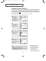
Viewing an External Signal Source . . . . . . . . . . . . . . . . . . . . . . . . . .3.11
04-CONTENTS_en 2/25/03 8:48 AM Page 3

4
CONTENTS
Chapter 4: Special Features . . . . . . . . . . . .4.1
Fine Tuning Channels . . . . . . . . . . . . . . . . . . . . . . . . . . . . . . . . . . . . . .4.1
LNA (Low Noise Amplifier) . . . . . . . . . . . . . . . . . . . . . . . . . . . . . . . .4.2
Changing the Screen Size . . . . . . . . . . . . . . . . . . . . . . . . . . . . . . . . . . .4.3
Freezing the Picture . . . . . . . . . . . . . . . . . . . . . . . . . . . . . . . . . . . . . . .4.3
Special Sound Options . . . . . . . . . . . . . . . . . . . . . . . . . . . . . . . . . . . . .4.4
Choosing a Multi-Channel Soundtrack (MTS) . . . . . . . . . . .4.4
Virtual Dolby . . . . . . . . . . . . . . . . . . . . . . . . . . . . . . . . . . . . .4.5
Setting the Sleep Timer . . . . . . . . . . . . . . . . . . . . . . . . . . . . . . . . . . . .4.6
Viewing Closed Captions . . . . . . . . . . . . . . . . . . . . . . . . . . . . . . . . . . .4.7
Viewing Picture-in-Picture . . . . . . . . . . . . . . . . . . . . . . . . . . . . . . . . . .4.8
Activating Picture-in-Picture . . . . . . . . . . . . . . . . . . . . . . . . .4.8
Selecting a Signal Source (External A/V) for PIP . . . . . . . . .4.9
Changing the Location of the PIP Window . . . . . . . . . . . . . .4.9
Changing the Size of the PIP Window . . . . . . . . . . . . . . . . . .4.9
Using the V-Chip . . . . . . . . . . . . . . . . . . . . . . . . . . . . . . . . . . . . . . . .4.10
Setting Up Your Personal ID Number (PIN) . . . . . . . . . . . .4.10
How to Enable/Disable the V-Chip . . . . . . . . . . . . . . . . . . .4.11
How to Set up Restrictions Using the “TV guidelines” . . . .4.11
How to Set up Restrictions using the MPAA Ratings:
G, PG, PG-13, R, NC-17, X . . . . . . . . . . . . . . . . . . . . . . . .4.13
How to Reset the TV after the V-Chip Blocks a Channel (“Emergency Escape”)
. . . . .4.14
Chapter 5: PC Display . . . . . . . . . . . . . . . . .5.1
Using Your TV as a Computer (PC) Display . . . . . . . . . . . . . . . . . . . .5.1
How to Connect Your PC to the TV . . . . . . . . . . . . . . . . . . .5.1
How to Set up Your PC display . . . . . . . . . . . . . . . . . . . . . . .5.2
How to Set up Your PC Software (Windows 2000) . . . . . . . .5.2
Adjusting the Screen Quality . . . . . . . . . . . . . . . . . . . . . . . . .5.3
Changing the Screen Position . . . . . . . . . . . . . . . . . . . . . . . .5.4
Changing the Screen Color Standard . . . . . . . . . . . . . . . . . . .5.5
Adjusting the Screen Color Settings . . . . . . . . . . . . . . . . . . .5.6
To Initialize the Screen Position or Color Settings . . . . . . . .5.7
Adjusting the PC Screen Automatically . . . . . . . . . . . . . . . .5.8
Chapter 6: Troubleshooting . . . . . . . . . . . .6.1
Identifying Problems . . . . . . . . . . . . . . . . . . . . . . . . . . . . . . . . . . . . . .6.1
Appendix . . . . . . . . . . . . . . . . . . . . . . . . . . .A.1
Retractable Stand . . . . . . . . . . . . . . . . . . . . . . . . . . . . . . . . . . . . . . . . .A.1
Using the Anti-Theft Kensington Lock . . . . . . . . . . . . . . . . . . . . . . . .A.1
Pin Assignments . . . . . . . . . . . . . . . . . . . . . . . . . . . . . . . . . . . . . . . . .A.2
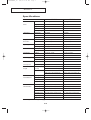
Display Modes . . . . . . . . . . . . . . . . . . . . . . . . . . . . . . . . . . . . . . . . . . .A.3
Cleaning and Maintaining Your TV . . . . . . . . . . . . . . . . . . . . . . . . . . .A.4
Using Your TV in Another Country . . . . . . . . . . . . . . . . . . . . . . . . . . .A.4
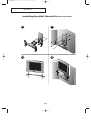
Installing the Wall Mount Kit . . . . . . . . . . . . . . . . . . . . . . . . . . . . . . .A.5
Specifications . . . . . . . . . . . . . . . . . . . . . . . . . . . . . . . . . . . . . . . . . . . .A.6
04-CONTENTS_en 4/4/03 1:44 PM Page 4

1.1
List of Features
Your TV was designed with the latest technology.
This TV is a high-performance unit that includes the following special features:
• Easy-to-use remote control
• Easy-to-use on-screen menu system
• Adjustable picture and sound settings that can be stored in the TV’s memory
• Automatic channel tuning for up to 181 channels
• A special filter to reduce or eliminate reception problems
• Fine tuning control for the sharpest picture possible
• A built-in multi-channel sound decoder for stereo and bilingual listening
• Built-in, dual channel speakers
• A special sleep timer
• Headphone jack for private listening
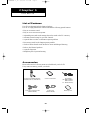
Accessories
Please make sure the following items are included with your LCD TV.
If any items are missing, contact your dealer.
Chapter 1
YOUR NEW TV
Remote Control (BN59-00302A) &
Batteries (AAAx 2) (4301-000121)
Owner’s Instructions DC Adapter
(15”:BN44-00080A
BN44-00071A
17” : BN44-00075A)
Power Cord
(BH39-10339X)
Warranty Card
15-pin D-Sub Signal Cable
(BN39-00043A)
05-CHAPTER 1_en 2/25/03 2:56 PM Page 1

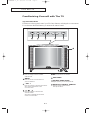
1.2
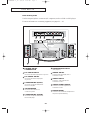
Familiarizing Yourself with The TV
Top Panel Buttons
The buttons on the top panel control your TV’s basic features, including the on-screen menu.
To use the more advanced features, you must use the remote control.
YOUR NEW TV
TV/VIDEO
Press to display all of the available
video sources.
MENU
Press to see an on-screen menu of
your TV's features.
- VOL +
Press to increase or decrease the volume.
Also used to select items on the
on-screen menu.
Press to increase or decrease the
channel number.
Also press to highlight various items
on the on-screen menu.
POWER
Press to turn the TV on and off.
SPEAKER
POWER INDICATOR
Lights up when you turn the power off.
REMOTE CONTROL SENSOR
Aim the remote control towards
this spot on the TV.
05-CHAPTER 1_en 4/15/03 2:56 PM Page 2

1.3
YOUR NEW TV
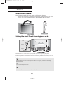
POWER INPUT
CONNECTOR
PC VIDEO INPUT
Connect to the video output port on your PC.
PC AUDIO INPUT
Connect to the audio-output jacks
on your PC.
COMPONENT 2(DTV)
Connect a component video/audio
from a Set-Top Box.
TV ANTENNA
Connect to an antenna or to
a cable TV system.
COMPONENT 1(DVD)
Connect a component video/audio
from a DVD player.
KENSINGTON LOCK
(See page A.1)
AUDIO INPUT
Connect audio signal(L/R) from a
camcorder or VCR.
VIDEO INPUT
Connect a video signal from a
camcorder or VCR.
SUPER VIDEO INPUT
Connect an S-Video signal from a
camcorder or VCR.
HEADPHONE
Connect a set of external headphones to
this jack for private listening.
Rear Panel Jacks
Use the rear panel jacks to connect an A/V component, such as a VCR or a DVD player.
For more information on connecting equipment, see pages 2.1 – 2.8.
05-CHAPTER 1_en 4/4/03 8:54 AM Page 3

1.4
YOUR NEW TV
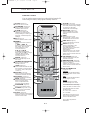
Remote Control
You can use the remote control up to about 23 feet from the TV
When using the remote, always point it directly at the TV.
Power
(Page 3.1)
Turns the TV on and off.
TV/VIDEO
(Page 3.11)
Press to display all of the
available video sources.
P. ST D
(Page 3.8)
Adjust the TV picture by
selecting one of the preset
factory settings (or select your
personal, customized picture
settings).
PC
(Page 5.1)
Press to switch to the PC mode.
MENU
Displays the main on-screen
menu.
- VOL / VOL +
Press to increase or decrease
the volume. (Also used to
make selections on the
on-screen menus.)
CH ▲ / CH ▼
(Channel Up/Down)
Press CH▲ or CH▼ to change
channels. (Also used to
highlight selections on the
on-screen menus.)
MUTE
(Page 3.6)
Press to temporarily cut off
the sound.
NUMBER BUTTONS
Press to select channels
directly on the TV.
+100
(Page 3.5)
Press to select channels over 100.
For example, to select channel
121, press “+100,” then press
“2” and “1.”
SLEEP
(Page 4.6)
Press to select a preset time
interval for automatic shutoff.
ASPECT
(Page 4.3)
Press to change the screen size.
MTS
(Page 4.4)
(Multichannel Television Stereo)
Press to choose stereo,
mono or Separate Audio
Program (SAP broadcast).
CAPTION
(Page 4.7)
Press to set caption on/off.
V.CHIP
(Page 4.10~4.14)
Press to set up and activate
the parental locks.
STILL
(Page 4.3)
Press to stop the action during a
particular scene. Press again to
resume normal video.
S.STD
(Page 3.10)
Adjust the TV sound by selecting
one of the preset factory settings
(or select your personal,
customized sound settings).
DISPLAY
(Page 3.1)
Press to display the current
channel and the audio-video
settings.
EXIT
Press the menu to exit.
When the PIP is active, press
the Exit button to turn PIP off.
PRE-CH
(Page 3.5)
Tunes to the previous channel.
AUTO
(Page 5.8)
Press to self-adjust to the
incoming video signal.
The values of fine, coarse and
position are adjusted
automatically.
(It does work only in PC mode.)
It works only in PC full- screen
mode. It does not work when the
PIP is active.
CH.SCAN
(Page 3.3)
Press to memorize (scan) the
available channels.
ADD/ERASE
(Page 3.5)
Press to add or erase channels
in the TV’s memory.
It works only in PC full- screen
mode. It does not work when the
PIP is active.
PIP CONTROLS
(Page 4.8~4.9)
LOCATE
Press to move the PIP window
to any of the four corners of the
TV screen.
SIZE
Press to make the PIP window
double, large or small.
PIP ON
Activates picture in picture
window directly in PC mode.
It is available in PC mode only
It does not work on other screen.
Push PIP ON button to switch
the PIP source:
PC + ant -> PC + Video ->
PC + S-Video.
If the PIP is active, the sound
of PC mode is switched to the
sound of the PIP screen.
To turn PIP off, press the
Exit button.
05-CHAPTER 1_en 5/14/03 9:37 AM Page 4

2.1
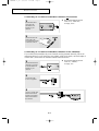
Connecting VHF and UHF Antennas
If your antenna has a set of leads that
look like this, see “Antennas with
300-ohm Flat Twin Leads,” below.
If your antenna has one lead that looks
like this, see “Antennas with 75-ohm
Round Leads,” on page 2.2.
If you have two antennas, see “Separate
VHF and UHF Antennas,” on page 2.2.
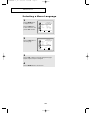
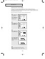
Antennas with 300-ohm Flat Twin Leads
If you are using an off-air antenna (such as a roof antenna or “rabbit ears”) that has
300-ohm twin flat leads, follow the directions below.
Chapter 2
INSTALLATION
1
Place the wires from the
twin leads under the
screws on a 300-75 ohm
adaptor (not supplied).
Use a screwdriver to
tighten the screws.
2
Plug the adaptor into the
TVANTENNA terminal
on the bottom of the
back panel.
06-CHAPTER 2_en 2/25/03 9:22 AM Page 1

2.2
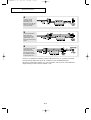
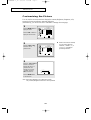
Connecting Cable TV
To connect to a cable TV system, follow the instructions below.
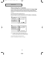
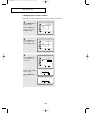
Cable without a Cable Box
1
Plug the incoming cable
into the TVANTENNA
antenna terminal on
back of the TV.
¥ Because this TV is
cable-ready, you do not need a
cable box to view unscrambled
cable channels.
2
Plug the combiner into
the TVANTENNA
terminal on the bottom
of the rear panel.
INSTALLATION
Antennas with 75-ohm Round Leads
1
Plug the antenna lead
into the TVANTENNA
terminal on the bottom
of the back panel.
Separate VHF and UHF Antennas
If you have two separate antennas for your TV (one VHF and one UHF), you must
combine the two antenna signals before connecting the antennas to the TV.
This procedure requires an optional combiner-adaptor (available at most electronics shops).
1
Connect both antenna
leads to the combiner.
06-CHAPTER 2_en 2/25/03 9:22 AM Page 2

2.3
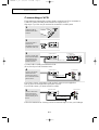
INSTALLATION
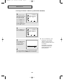
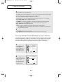
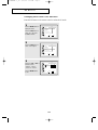
Connecting to a Cable Box that Descrambles All Channels
1
Find the cable that is
connected to the
ANTENNA OUT
terminal on your
cable box.
¥ This terminal might be labeled
“ANT OUT,” “VHF OUT,”
or simply, “OUT.”.
2
Connect the other end
of this cable to the
TVANTENNA terminal
on the back of the TV.
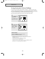
Connecting to a Cable Box that Descrambles Some Channels
If your cable box descrambles only some channels (such as premium channels), follow the
instructions below. You will need a two-way splitter, an RF (A/B) switch, and four lengths of
coaxial cable. (These items are available at most electronics stores.)
1
Find and disconnect the
cable that is connected
to the ANTENNA IN
terminal on your
cable box.
¥ This terminal might be labeled
“ANT IN,” “VHF IN,”
or simply, “IN.”.
2
Connect this cable
to a two-way splitter.
3
Connect a coaxial cable
between an OUTPUT
terminal on the splitter
and the IN terminal on
the cable box.
06-CHAPTER 2_en 2/25/03 9:22 AM Page 3

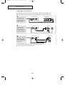
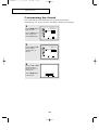
2.4
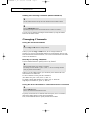
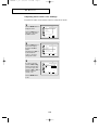
4
Connect a coaxial
cable between the
ANTENNA OUT
terminal on the cable box
and the B–IN terminal
on the A/B switch.
5
Connect another cable
between the other
OUT terminal on the
splitter and the A–IN
terminal on the RF (A/B)
switch.
6
Connect the last coaxial
cable between the
OUT terminal on the
RF (A/B) switch and
the VHF/UHF terminal
on the rear of the TV.
INSTALLATION
After you’ve made this connection, set the A/B switch to the “A” position for normal
viewing. Set the A/B switch to the “B” position to view scrambled channels.
(When you set the A/B switch to “B,” you will need to tune your TV to the cable box’s
output channel, which is usually channel 3 or 4.)
06-CHAPTER 2_en 2/25/03 9:22 AM Page 4

2.5
INSTALLATION
3
Connect a coaxial cable
between the ANTENNA
OUT terminal on the
VCR and the antenna
terminal on the TV.
4
Connect a set of audio
cables between the
AUDIO OUT jacks on
the VCR and the AUDIO
jacks on the TV.
5
Connect a video cable
between the VIDEO
OUT jack on the VCR
and the VIDEO jack on
the TV.
Follow the instructions in “Viewing a VCR or Camcorder Tape” to view your VCR tape.
A coaxial cable is usually included with a VCR.
(If not, check your local electronics store).
If you have a “mono” (non-stereo) VCR, use the Y-connector (not supplied) to
hook up to the left and right audio input jacks of the TV.
If your VCR is stereo, you must connect two cables.
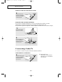
Connecting a VCR
These instructions assume that you have already connected your TV to an antenna or
a cable TV system (according to the instructions on pages 2.1-2.3).
Skip step 1 if you have not yet connected to an antenna or a cable system.
1
Unplug the cable or
antenna from the back
of the TV.
2
Connect the cable or
antenna to the
ANTENNA IN terminal
on the back of the VCR.
VCR Rear Panel
VCR Rear Panel
VCR Rear Panel TV Rear Panel
TV Rear Panel
TV Rear Panel
Coaxial Cable
Audio Cable
Video Cable
Pr
Audio(L) Audio(R)
06-CHAPTER 2_en 2/25/03 9:22 AM Page 5

2.6
INSTALLATION
3
Connect an S-video cable
between the S-VIDEO
OUT jack on the VCR
and the S-VIDEO INPUT
jack on the TV.
An S-Video cable is usually included with an S-VHS VCR.
(If not, check your local electronics store.)
1
To begin, follow steps
1–3 in the previous
section to connect the
antenna or cable to your
VCR and your TV.
Connecting an S-VHS VCR
Your Samsung TV can be connected to an S-Video signal from an S-VHS VCR.
(This connection delivers a better picture as compared to a standard VHS VCR.)
2
Connect a set of audio
cables between the
AUDIO OUT jacks on
the VCR and the AUDIO
INPUT jacks on the TV.
VCR Rear Panel TV Rear Panel
Coaxial Cable
Pr
Audio(L) Audio(R)
VCR Rear Panel TV Rear Panel
Audio Cable
VCR Rear Panel TV Rear Panel
S-Video Cable
06-CHAPTER 2_en 2/25/03 9:22 AM Page 6

2.7
INSTALLATION
Note: For an explanation of Component video, see your DVD player owner's manual.
Connecting a DVD Player
The rear panel jacks on your TV make it easy to connect a DVD player to your TV.
1
Connect a set of audio
cables between the
COMPONENT 1 L, R
AUDIO INPUT jacks on
the TV and the AUDIO
OUT jacks on the DVD
player.
2
Connect a video cable
between the
COMPONENT1
(Y, Pb, Pr) jacks on the
TV and the Y, Pb, Pr
jacks on the DVD player.
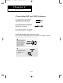
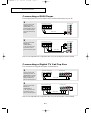
Note: For an explanation of Component video, see your Set-Top Box owner's manual.
Connecting a Digital TV Set-Top Box
The connections for a typical set-top box are shown below.
1
Connect a set of audio
cables between the L, R
COMPONENT2 AUDIO
INPUT jacks on the TV
and the AUDIO OUT
jacks on the Set-Top Box.
2
Connect a video cable
between the
COMPONENT2
(Y, Pb, Pr) jacks on the
TV and the Y, Pb, Pr
jacks on the Set-Top Box.
DVD Player Rear Panel TV Rear Panel
Audio Cable
DVD Player Rear Panel TV Rear Panel
Video Cable
Set Top Box Rear Panel TV Rear Panel
Audio Cable
Set Top Box Rear Panel TV Rear Panel
Video Cable
06-CHAPTER 2_en 2/25/03 9:22 AM Page 7

2.8
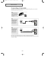
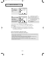
2
Connect an audio cable
between the AUDIO
OUTPUT jack on the
camcorder and the
AUDIO terminals on
the back of the TV.
3
Connect a video cable
between the VIDEO
OUTPUT jack on the
camcorder and the
VIDEO terminal on
the back of the TV.
1
Locate the A/V output
jacks on the camcorder.
They are usually found on
the side or back of the
camcorder.
Connecting a Camcorder
The jacks on your TV make it easy to connect a camcorder. They allow you to view the
camcorder tapes without using a VCR.
The audio-video cables shown here are usually included with a Camcorder.
(If not, check your local electronics store.) If your camcorder is stereo, you need to connect
a set of two cables.
INSTALLATION
Camcorder
Output Jacks
Y-Connector
TV Rear Panel
TV Rear Panel
Audio Cable
Camcorder
Output Jacks
Video Cable
06-CHAPTER 2_en 2/25/03 9:22 AM Page 8

2.9
INSTALLATION
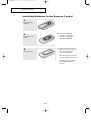
3
Replace the cover.
¥ Remove the batteries and store
them in a cool, dry place if you
won’t be using the remote
control for a long time.
The remote control can be used
up to about 23 feet from the TV.
(Assuming typical TV usage,
the batteries last for about
one year.)
2
Install two AAA size
batteries.
¥ Make sure to match the
“
+” and “–” ends of the
batteries with the diagram
inside the compartment.
Installing Batteries in the Remote Control
1
Slide the cover out
completely.
06-CHAPTER 2_en 2/25/03 9:22 AM Page 9

3.1
Chapter 3
OPERATION
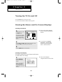
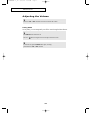
Turning the TV On and Off
Press the Power button on the remote control.
You can also use the Power button on the top panel.
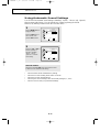
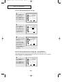
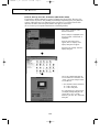
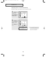
Viewing the Display
The display identifies the current channel and the status
of certain audio-video settings.
¥ The on-screen displays
disappear after about ten seconds.
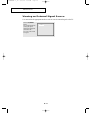
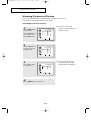
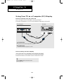
Viewing the Menus and On-Screen Displays
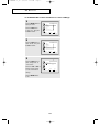
Viewing the Menus
1
With the power on, press
the MENU button.
The main menu appears
on the screen. Its left side
has five icons: Picture,
Sound, Channel, Function
and PC.
¥ The on-screen menus disappear
from the screen after about thirty
seconds.
Picture
Move Select
Exit
Mode Custom
Contrast
Brightness
Sharpness
Color
Tint
Color Tone Normal
¥ You can also use the Menu,
CHANNEL, and VOLUME
buttons on the control panel of
the TV to make selections.
1
Press the DISPLAY
button on the remote
control.
The TV will display the
channel, the type of
sound, and the status of
certain picture and sound
settings.
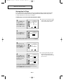
2
Use the CH▲ and CH▼ buttons to select one of the 5 icons.
Then press VOL+ to access the icon’s sub-menu.
3
Press the MENU button to exit the menu.
Ant 4
Picture Mode : Custom
Sound Mode : Custom
MTS : Stereo
Signal : Mono
Caption : Off
V-Chip : No
07-CHAPTER 3_en 2/25/03 9:28 AM Page 1
Page is loading ...
Page is loading ...
Page is loading ...
Page is loading ...
Page is loading ...
Page is loading ...
Page is loading ...
Page is loading ...
Page is loading ...
Page is loading ...
Page is loading ...
Page is loading ...
Page is loading ...
Page is loading ...
Page is loading ...
Page is loading ...
Page is loading ...
Page is loading ...
Page is loading ...
Page is loading ...
Page is loading ...
Page is loading ...
Page is loading ...
Page is loading ...
Page is loading ...
Page is loading ...
Page is loading ...
Page is loading ...
Page is loading ...
Page is loading ...
Page is loading ...
Page is loading ...
Page is loading ...
Page is loading ...
Page is loading ...
Page is loading ...
Page is loading ...
Page is loading ...
Page is loading ...
Page is loading ...
Page is loading ...
-
 1
1
-
 2
2
-
 3
3
-
 4
4
-
 5
5
-
 6
6
-
 7
7
-
 8
8
-
 9
9
-
 10
10
-
 11
11
-
 12
12
-
 13
13
-
 14
14
-
 15
15
-
 16
16
-
 17
17
-
 18
18
-
 19
19
-
 20
20
-
 21
21
-
 22
22
-
 23
23
-
 24
24
-
 25
25
-
 26
26
-
 27
27
-
 28
28
-
 29
29
-
 30
30
-
 31
31
-
 32
32
-
 33
33
-
 34
34
-
 35
35
-
 36
36
-
 37
37
-
 38
38
-
 39
39
-
 40
40
-
 41
41
-
 42
42
-
 43
43
-
 44
44
-
 45
45
-
 46
46
-
 47
47
-
 48
48
-
 49
49
-
 50
50
-
 51
51
-
 52
52
-
 53
53
-
 54
54
-
 55
55
-
 56
56
-
 57
57
-
 58
58
-
 59
59
-
 60
60
-
 61
61


Ask a question and I''ll find the answer in the document
Finding information in a document is now easier with AI
Related papers
-
Samsung LTM1775W User manual
-
Samsung CL-29M16MQ User manual
-
-
-
-
-
-
-
Samsung TXN2730F User manual
-
Other documents
-
Sanyo AVL-191 User manual
-
Haier HLTDC15 User manual
-
-
RCA CR20401 User manual
-
-
-
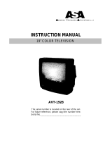 ASA Electronics AVT-1928 User manual
-
Daewoo Projection Television DSJ-4710CRA User manual
-
-
Sherwood TL-1705W Operating Instructions Manual
