Page is loading ...


Digital Video Recorder
i
WARNING
RISK OF ELECTRIC SHOCK
DO NOT OPEN
WARNING: TO REDUCE THE RISK OF ELECTRIC SHOCK,
DO NOT REMOVE COVER (OR BACK).
NO USER-SERVICEABLE PARTS INSIDE.
REFER SERVICING TO QUALIFIED
SERVICE PERSONNEL.
The lightning flash with arrowhead symbol, within an equilateral triangle,
is intended to alert the user to the presence of uninsulated "dangerous
voltage" within the product's enclosure that may be of sufficient magnitude
to constitute a risk of electric shock.
The exclamation point within an equilateral triangle is intended to alert
the user to the presence of important operating and maintenance
(servicing) instructions in the literature accompanying the appliance.
WARNING:
TO PREVENT FIRE OR SHOCK HAZARD, DO NOT EXPOSE THIS APPLIANCE TO RAIN
OR MOISTURE.
CAUTION:
TO PREVENT ELECTRIC SHOCK DO NOT USE THIS (POLARIZED) PLUG WITH AN
EXTENSION CORD, RECEPTACLE OR OTHER OUTLET UNLESS THE BLADES CAN BE
FULLY INSERTED TO PREVENT BLADE EXPOSURE.

User’s Manual
ii
AVERTISSEMENT
DANGER D’ÉLECTROCUTION
NE PAS OUVRIR
AVERTISSEMENT: POUR ÉLIMINER TOUT RISQUE D’ÉLECTRO-
CUTION, NE PAS OUVRIR LE COUVERCLE (OU LA
PARTIE ARRIÈRE). AUCUNE PIECE RÉPARABLE
PAR L’UTILISATEUR NE SE TROUVE À L’INTÉRIEUR.
POUR TOUTE INTERVENTION D’ENTRETIEN OU
DE RÉPARATION SE CONFIER AUX TECHNICIENS
QUALIFIÉS.
La fl èche symbolisant l’éclair dans un triangle équilateral a pour objet de
tirer l’attention de l’utilisateur sur le fait, qu’ il y a des “tensions dangereuses”
non-isolées à l’intérieur de l’enceinte du produit qui peuvent être suf fi
samment importantes pour conduire au risque d’électrocution.
Le point d’exclamation au sein d’un triangle équilateral a pour objet de
tirer l’attention de l’utilisateur sur le fait qu’ il y a des instructions de mise
en service et d’entretien (de réparation) dans les fi ches descriptives de
l’appareil qui doivent obligatoirement être respectées.
AVERTISSEMENT:
AFIN D’ÉVITER TOUT RISQUE D’INCENDIE OU D’ÉLECTROCUTION, NE PAS EXPOSER
CET APPAREIL À LA PLUIE NI À L’HUMIDITÉ.
ATTENTION:
POUR PRÉVENIR LES CHOCS ÉLECTRIQUES NE PAS UTILISER CETTE FICHE
POLARISÉE AVEC UN PROLONGATEUR, UNE PRISE DE COURANT OU UNE AUTRE
SORTIE DE COURANT, SAUF SI LES LAMES PEUVENT ÊTRE INSÉRÉES À FOND SANS
EN LAISSER AUCUNE PARTIE À DÉCOUVERT.

Digital Video Recorder
iii
Important safeguards
PLEASE READ ALL THESE INSTRUCTIONS REGARDING YOUR RECORDER AND RETAIN
FOR FUTURE REFERENCE. FOLLOW ALL WARNINGS AND INSTRUCTIONS MARKED ON
THE RECORDER.
1. Read Instructions
All the safety and operating instructions should be read before the
appliance is operated.
2. Retain Instructions
The safety and operating instructions should be retained for future
reference.
3. Heed Warnings
All warnings on the appliance and in the operating instructions should
be adhered to.
4. Follow Instructions
All operating and use instructions should be followed.
5. Cleaning
Unplug this product from the wall outlet before cleaning. Do not
use liquid or aerosol cleaners. Use a damp cloth for cleaning.
6. Attachments
Do not use attachments not recommended by the product manufacturer
as they may cause hazards.
7. Water and Moisture
Do not use this product near water – for example, near a bath tub,
wash bowl, kitchen sink, or laundry tub, in a wet basement, or near
a swimming pool, and the like.
8. Accessories
Do not place the product on an unstable cart, stand, tripod, bracket, or
table. The product may fall, causing serious injury. Any mounting
of the appliance should follow the manufacturer’s instructions, and
should use a mounting accessory instructions, and should use a
mounting accessory.
An appliance and cart combination should be moved with care. Quick
stops, excessive force, and uneven surfaces may cause the appliance
and cart combination to overturn.
12. Powe
r
-Cord Protection
Power-supply cords should be routed so that they are not likely to be
walked on or pinched by items placed upon or against them, paying
particular attention to cord at plugs, convenience receptacles, and the
point where they exit from the appliance.
13. Lightning
For added protection for this product receiver during a lightning storm,
or when it is left unattended and unused for long periods of time,
unplug it from the wall outlet. This will prevent damage to the product
due to lightning and power-line surges.
14. Overloading
Do not overload wall outlets and extension cords as this can result in
a risk of fire or electric shock.
15. Object and Liquid Entry
Never spill liquid of any kind on the product.
16. Servicing
Do not attempt to service this product yourself as opening or removing
covers may expose you to dangerous voltage or other hazards. Refer
all servicing to qualified service personnel.
17. Damage requiring Service
Unplug this product from the wall outlet and refer servicing to qualified
service personnel under the following conditions:
A. When the power-supply cord or plug is damaged.
B. If liquid has been spilled, or objects have fallen into the product.
C. If the product has been exposed to rain or water.
D. If the product does not operate normally by following the operating
instructions. Adjust only those controls that are covered by the
operating instructions as an improper adjustment of other controls
may result in damage and will often require extensive work by a
qualified technician to restore the product to its normal operation.
E. If the product has been dropped or the cabinet has been damaged.
F. When the product exhibits a distinct change in performance, this
indicates a need for service.
18. Replacement Parts
When replacement parts are required, be sure the service technician
has used replacement parts specified by the manufacturer or have the
same characteristics as the original part. Unauthorized substitutions
may result in fire, electric shock or other hazards.
19. Safety Check
Upon completion of any service or repairs to this product, ask the service
technician to perform safety checks to determine that the product is
in safe operating conditions.
20. Heat
The product should be situated away from heat sources such as radiators,
heat registers, stoves, or other products (including amplifiers) that
product heat.
21. Correct Batteries
Warning: Risk of explosion if battery is replaced by an incorrect type.
Dispose of used batteries according to the instructions.
22. This equipment does not provide connection for used with
outdoor or cable distribution systems.
9. Ventilation
Slots and openings in the cabinet are provided for ventilation and
to ensure reliable operation of the product and to protect it from
overheating, and these openings must not be blocked or covered. This
product should never be placed near or over a radiator or heat register.
This product should not be placed in a built-in installation such as
a bookcase or rack unless proper ventilation is provided or the
manufacturer’s instructions have been adhered to.
10. Power Sources
This product should be operated only from the type of power source
indicated on the marking label. For products intended to operate from
battery power, other sources, refer to the operating instructions.
11. Grounding or Polarization
This product is equipped with a 3-wire grounding-type plug, a plug
having a third (grounding) pin. This plug will only fit into a grounding-
type power outlet. This is a safety feature. If you are unable to insert
the plug into the outlet, contact your electrician to replace your obsolete
outlet. Do not defeat the safety purpose of the grounding-type plug.

User’s Manual
iv
NOTE
This equipment has been tested and found to comply with the limits for a Class A digital device, pursuant to Part 15 of
the FCC Rules. These limits are designed to provide reasonable protection against harmful interference when the
equipment is operated in a commercial environment. This equipment generates, uses, and can radiate radio
frequency energy and, if not installed and used in accordance with the instruction manual, may cause harmful
interference to radio communications. Operation of this equipment in a residential area is likely to cause harmful
interference in which case the user will be required to correct the interference at his own expense. Changes or
modifications not expressly approved by the party responsible for compliance could void the user's authority to
operate the equipment.
NOTE
THIS CLASS A DIGITAL APPARATUS COMPLIES WITH CANADIAN ICES-003.
CET APPAREIL NUMÉRIQUE DE LA CLASSE A EST CONFORME À LA NORME NMB-003 DU CANADA.
Microsoft, Windows and Windows Vista are either registered trademarks or trademarks of Microsoft Corporation in
the United States and/or other countries.
All other company and product names appearing herein are the property of their respective owners.

Digital Video Recorder
v
Caution and care
HEAVY OBJECTS SHOULD NEVER BE PLACED ON THE UNIT (E.G., MONITOR)
NEVER REMOVE THE TOP COVER AND TOUCH OR INSERT ANY OBJECT INSIDE THE UNIT
Touching the inside of the cabinet or inserting foreign objects of any kind through the disc loading slot or ventilation holes not only creates
a safety hazard but can also cause extensive damage.
PROTECT THE POWER CORD
Damage to the power cord may cause fire or electrical shock. If the power cord is damaged, turn OFF the MAIN switch and carefully replace
it with a new power cord.
Do not move this product with the power-on as the built-in HDD may be damaged. If you need to move the product, turn the unit OFF and
disconnect power from the unit. Confirm that more than one minute has passed since the power cord and the connecting cords were disconnected,
then move this unit. Make sure to take the disc out and close the disc loading slot.
UNPLUG THE POWER CORD DURING A LONG ABSENCE
Turn off the power and unplug the power cord during a long absence.
MAINTAIN GOOD VENTILATION
Do not obstruct the many ventilation holes on the unit. For maximum ventilation, leave some space around the unit and place the unit on
a hard level surface only, and ensure it is not covered during use. Heavy objects should never be placed on the unit.
WHEN NOT IN USE
When not in use, always eject the disc and turn OFF the MAIN switch.
CABINET CARE
Never use petroleum-based cleaners. Clean with a soft cloth moistened with soap and water and wipe dry.
PVC cables or leads should not be left in contact with the cabinet surface for long periods.
INSTALLATION LOCATION
For excellent performance and lasting reliability install in a location that is:-
1. Well ventilated, out of direct sunlight and away from direct heat.
2. A solid vibration-free surface.
3. Free from high humidity, excessive dust and away from magnetic fields.
4. Please ensure that the ventilation fan located on the unit’s back panel is not blocked.
UNSUITABLE LOCATIONS
Placing the unit in the following places might shorten the product life:
Extremely cold places, such as refrigerated warehouses and ice houses
Places where excessive hydrogen sulfide is likely to be generated, such as hot-springs areas
Places or locations with salt air environment.
NO OBJECTS FILLED WITH LIQUIDS, SUCH AS VASES, SHALL BE PLACED ON THE APPARATUS.
DO NOT PLACE HEAVY OBJECT ON THIS UNIT.
DO NOT STEP ONTO THIS UNIT.
DO NOT PLACE ANY OBJECTS IN FRONT OF THE DISC LOADING SLOT.
The unit may drop or fall by losing its balance. It may cause injury or failure of the unit.
WARNING:
TO PREVENT FIRE OR SHOCK HAZARD, DO NOT EXPOSE THIS APPARATUS TO RAIN OR MOISTURE.
THIS APPARATUS MUST BE GROUNDED.
WARNING:
The supplied power cord is used for 120 V only. Never connect to any outlet or power supply having a different voltage or
frequency.
Notice about construction of the surveillance system using this unit
This unit can be controlled by the external devices via RS-232C terminal or NETWORK terminal. This unit can also be used to control
external devices via external terminal, or RS-232C terminal. Owning to these functions, this unit flexibly applies to the high grade
security system, but the whole surveillance system may be affected by the malfunction of this unit or the external devices depending
on the setting contents of this unit, the connection with the external devices,, or combination between this unit and the external devices.
When configuring a surveillance system using this unit, it is recommended to confirm first that this unit operates normally with the
other devices connected.
It is recommended to copy or back up the important recorded contents.
Damages rising out of any operational error of the surveillance system or loss of the recorded data or any other damages because
of any user malfunction of this unit are not covered.
Do not use the notification function of this unit for making critical judgment nor nay purpose related to human lives.
When this unit cannot recognize the external device which is being used for recording due to the power failure, decreased voltage,
or other failures, the recording point may be moved to the internal HDD of this unit or the other external HDD. To prevent occurrence
of such problem, it is recommended to use uninterruptible power supply.
If the power plug is disconnected or the breaker switch is turned off during recording, HDD may be damaged or playback of recorded
data may become impossible.
If the breaker switch is turned on and off everyday, set the timer recording to be performed only for the period that the breaker is on
and do not turn off the breaker during recording.

User’s Manual
vi
CLASS 1 LASER PRODUCT
There may be cases when the unit’s built-in motion detection function does not operate properly due to external condition, video input
signal, or other factors.
The user will not be indemnified for problems (e.g., recording failure or playback failure) that occur with either the unit or a connected
device during operation. It is recommended to back up the important recordings regularly as a precaution against possible breakdowns
and accidents.
This unit uses a built-in HDD, which is a precision device. Handle this unit with sufficient care
Do not subject this unit to vibrations or shocks. This may cause trouble specially when the power of the unit is turned on or when
the HDD is being accessed, and sufficient care is required.
Do not disconnect the power plug while the power of the unit is turned on or while recording or playing.
For early detection of faults, we recommend that you request inspection once a year.
The HDD and cooling fan of this unit are driving parts. For stable recording, it is recommended that both of these parts are replaced
every 30,000 hours.
(This interval is for reference purpose only and does not indicate the warranty period of the parts.)
DISCLAIMER
In any event, Mitsubishi assumes no responsibility or reliability for the following:
1. Disassembly, repair, or alteration of this unit by user or installer.
2. Failure or breakdown in or damage to this unit resulting from misuse or careless handling by user or installer.
3. Inconvenience or damages arising out of inability to display of record pictures due to any reason or cause other than breakdown or
failure in this unit.
4. Failure in this unit due to combination with other equipment manufactured by a third party or inconvenience or damages resulting
from such failure.
5. Inconvenience, damages, or claims arising out of breakdown in this unit or loss of recorded video data due to replacement of the
built-in HDD by user or installer.
6. Inconvenience or damages arising out of breakdown in this unit or inability to display or record pictures due to natural disaster including
earthquake and storm.
7. Inconvenience, damages, or claims arising out of breakdown in this unit or loss of recorded video data due to impact or vibration to
the built-in HDD or an environmental factor such as temperature at the installation site.
8. Demand for damages or other claim of infringement of privacy if the pictures monitored or recorded by user become public or are
used for any purpose other than surveillance for whatever reason.
INSTALLATION LOCATION AND HANDLING
Place this unit horizontally an in a stable place. If this unit is not placed correctly and used in an unstable place, the unit may be damaged.
Do not place this unit close to other electronic or magnetic equipment. This will avoid video and audio distortion.
When a monitor and this unit are placed vertically, the pictures may be distorted.
PRECAUTION CONCERNING EXTERNAL DEVICE
The various external HDDs can be connected to this unit in order to expand the memory or to use as the copy device However, during
recording or playing back a picture at high rate, some pictures may be missed due to the slow rate of data transfer or the slow speed
of response from the external device connected. Be sure to check the operation sufficiently in advance.
Do not use the power control function of the external device which uses bus power of this unit.
The external device to be used may be unsuitable for the operation you want to set. It is recommended to consult your dealer when
using the external device.
ATTACHED POWER CORD
The attached power cord is to be used exclusively for this DVR. Never use them for other products.
The attached power cord is rated at 120 V AC. Never connect this cord to any outlet or power supply using other voltages or frequencies
than rated.
GENERAL INFORMATION ABOUT SOFTWARE APPLIED BY GNU GPL
This Digital Video Recorder equips software “BusyBox”, “Das U-boot”, “dvd+rw tools”, “MontaVista Linux Kernel”, “cdrtools”, “YAFFS”,
“pppoe” and “IJG JPEG” those are applied by GNU General Public License (GNU GPL). The users shall have the right to obtain, modify
and redistribute the source code of the software. For details, refer to the text file “gpl.txt” in the included Accessory CD.

Digital Video Recorder
vii
Table of Contents
Chapter 1 ─ Introduction .............................................................................................. 1
Features ................................................................................................................... 1
Technical Overview .................................................................................................. 1
Chapter 2 ─ Installation ................................................................................................ 3
Package Contents .................................................................................................... 3
Required Installation Tools ....................................................................................... 3
Video Input ........................................................................................................... 3
Video Loop Through ............................................................................................. 4
RS232C Port ........................................................................................................ 4
Factory Reset Switch ........................................................................................... 4
Alarm Input/Output ............................................................................................... 4
RS485 Port ........................................................................................................... 5
Network Port ......................................................................................................... 5
Video Out ............................................................................................................. 5
Audio In/Out ......................................................................................................... 5
Power Cord Connector ......................................................................................... 6
Chapter 3 ─ Configuration ............................................................................................ 7
Front Panel Controls ................................................................................................ 7
POWER LED ........................................................................................................ 7
HDD LED .............................................................................................................. 7
ALARM LED ......................................................................................................... 7
NETWORK LED ................................................................................................... 8
COPY LED ........................................................................................................... 8
Camera Buttons (1 to 16) ..................................................................................... 8
Display/Spot Button .............................................................................................. 8
Group/Sequence Button ....................................................................................... 8
PTZ/Zoom Button ................................................................................................. 8
Playback Button ................................................................................................... 8
Clip Copy Button .................................................................................................. 9
Alarm Button ......................................................................................................... 9
Play/Pause Button ................................................................................................ 9
Arrow Buttons ....................................................................................................... 9
Menu/Cameo Button ............................................................................................ 9
Panic Button ......................................................................................................... 9
USB Ports ........................................................................................................... 10
Turning on the Power ............................................................................................. 10
Initial Unit Setup ..................................................................................................... 10
Setup Screen .......................................................................................................... 11
System Setup ..................................................................................................... 11
Record Setup ..................................................................................................... 19
Event Setup ........................................................................................................ 23

User’s Manual
viii
Network Setup .................................................................................................... 30
Camera Setup .................................................................................................... 35
Device Setup ...................................................................................................... 37
Display Setup ..................................................................................................... 40
Status Screen ..................................................................................................... 43
Chapter 4 ─ Operation ............................................................................................... 45
Turning on the Power ............................................................................................. 45
Live Monitoring ....................................................................................................... 45
Live Monitoring Menu ......................................................................................... 46
PTZ Mode ........................................................................................................... 48
Zoom Mode ........................................................................................................ 49
Spot Monitoring .................................................................................................. 49
Active Cameo Mode ........................................................................................... 49
Event Monitoring ................................................................................................ 50
Covert Camera ................................................................................................... 50
Using a Mouse ....................................................................................................... 50
Recording Video ..................................................................................................... 51
Panic Recording ................................................................................................. 52
Recording Audio ..................................................................................................... 52
Playing Recorded Video ......................................................................................... 52
Searching Video ..................................................................................................... 53
Search Menu ...................................................................................................... 54
Record Table Search ......................................................................................... 55
Event Log Search ............................................................................................... 57
Text-In Search .................................................................................................... 58
Motion Search .................................................................................................... 59
Clip Copy ............................................................................................................ 60
Appendix A ─ USB Hard Disk Drive Preparation ....................................................... 63
Preparing the USB hard disk drive in Windows 2000 ............................................. 63
Preparing the USB hard disk drive in Windows 98 ................................................. 63
Appendix B ─ Text-In Search Examples .................................................................... 64
Search Example I ................................................................................................... 64
Search Example II .................................................................................................. 64
Appendix C ─ WebGuard ........................................................................................... 66
Web Monitoring Mode ............................................................................................ 67
Web Search Mode .................................................................................................. 68
Appendix D ─ Troubleshooting .................................................................................. 71
Appendix E ─ Connector Pin Outs ............................................................................. 72
I/O Connector Pin Outs .......................................................................................... 72
RS485 Connector Pin Outs .................................................................................... 72

Digital Video Recorder
ix
Appendix F ─ Map of Screens ................................................................................... 73
Appendix G ─ System Log Notices ............................................................................ 74
Appendix H ─ Error Code Notices .............................................................................. 75
Appendix I ─ Specifications ........................................................................................ 76

User’s Manual
x
List of Illustrations
Figure 1 ─ Typical DVR installation. .......................................................................................... 2
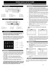
Figure 2 ─ 16-Channel DVR rear panel. .................................................................................... 3
Figure 3 ─ 16-Channel DVR front panel. ................................................................................... 7
Figure 4 ─ Setup screen. ......................................................................................................... 11
Figure 5 ─ System General setup screen. ............................................................................... 11
Figure 6 ─ Date/Time setup screen. ........................................................................................ 13
Figure 7 ─ Account setup screen. ............................................................................................ 15
Figure 8 ─ Storage setup screen. ............................................................................................ 17
Figure 9 ─ Monitoring setup screen. ........................................................................................ 18
Figure 10 ─ Record menu. ....................................................................................................... 19
Figure 11 ─ Record General setup screen. ............................................................................. 20
Figure 12 ─ Schedule (Basic) setup screen............................................................................. 21
Figure 13 ─ Schedule (Advanced) setup screen. .................................................................... 22
Figure 14 ─ Event menu. ......................................................................................................... 23
Figure 15 ─ Motion setup screen. ............................................................................................ 24
Figure 16 ─ Alarm-In setup screen. ......................................................................................... 26
Figure 17 ─ Video Loss setup screen. ..................................................................................... 27
Figure 18 ─ Text-In setup screen. ............................................................................................ 28
Figure 19 ─ Network Menu. ..................................................................................................... 30
Figure 20
─ Network General setup screen. ............................................................................ 30
Figure 21 ─ IP Address setup screen. ..................................................................................... 31
Figure 22 ─ DVRNS setup screen. .......................................................................................... 33
Figure 23 ─ Mail setup screen. ................................................................................................ 34
Figure 24 ─ Callback setup screen. ......................................................................................... 35
Figure 25 ─ Camera Menu. ...................................................................................................... 35
Figure 26 ─ Camera General setup screen. ............................................................................ 36
Figure 27 ─ PTZ setup screen. ................................................................................................ 36
Figure 28 ─ Device Menu. ....................................................................................................... 37
Figure 29 ─ Audio setup screen. .............................................................................................. 38
Figure 30 ─ Alarm-Out setup screen. ...................................................................................... 38
Figure 31 ─ Remote Control setup screen............................................................................... 39
Figure 32 ─ Display Menu. ....................................................................................................... 40
Figure 33 ─ OSD setup screen. ............................................................................................... 40
Figure 34 ─ Main Monitor setup screen. .................................................................................. 41
Figure 35 ─ Spot Monitor setup screen. .................................................................................. 42
Figure 36 ─ Status menu. ........................................................................................................ 43
Figure 37 ─ Event screen. ....................................................................................................... 43
Figure 38 ─ Storage screen. .................................................................................................... 44
Figure 39
─ Live Monitoring menu. .......................................................................................... 46
Figure 40 ─ Mouse Display menu. ........................................................................................... 50
Figure 41 ─ Search menu. ....................................................................................................... 53
Figure 42 ─ Record Table Search screen. ............................................................................... 55
Figure 43 ─ Event Log Search screen. .................................................................................... 57
Figure 44 ─ Text-In Search screen. ......................................................................................... 58
Figure 45 ─ Motion Search screen. ......................................................................................... 59
Figure 46 ─ Clip-Copy screen. ................................................................................................. 61
Figure 47 ─ WebWatch screen. ............................................................................................... 67
Figure 48 ─ WebSearch screen. .............................................................................................. 69

Digital Video Recorder
1
Chapter 1 ─ Introduction
FEATURES
Your color digital video recorder (DVR) provides recording capabilities for eight or 16 camera inputs. It
provides exceptional picture quality in both live and playback modes, and offers the following features:
8 or 16 Composite Video Input Connectors
Compatible with Color (NTSC or PAL) and B&W (CCIR and EIA-170) Video Sources
Auto Detection for NTSC and PAL
Multiple Monitor Connectors: 1 BNC Video Out, 1 Spot, 1 VGA
Dual Codec (MPEG-4 and H.264)
Multiple Search Engines (Date/Time, Calendar, Event)
Records up to 120/100 Images per Second (NTSC/PAL)
“Loop-Through” Video Connectors
Continuous Recording in Disk Overwrite Mode
2 USB 2.0 Ports
Continues Recording while Transmitting to Remote Site and during Playback
User-friendly Graphical User Interface (GUI) Menu System
Multiple Recording Modes (Time-lapse, Pre-event, Event and Panic)
4-Channel Audio Recording and 1-Channel Audio Playback
Two-way Audio Communication
Text Input for ATM and POS
Alarm Connections Include: Input, Output and Reset Input
Built-in Alarm Buzzer
Live or Recorded Video Access via Ethernet
Time Synchronization using industry standard protocol
Built-in DVD RW Drive
Self-diagnostics with automatic notification including hard disk drive S.M.A.R.T. protocol
TECHNICAL OVERVIEW
In addition to replacing both a time-lapse VCR and a multiplexer in a security installation, your DVR has
many features that make it much more powerful and easier to use than even the most advanced VCR.
The DVR converts analog NTSC or PAL video to digital images and records them on a hard disk drive.
Using a hard disk drive allows you to access recorded video almost instantaneously; there is no need to rewind
tape. The technology also allows you to view recorded video while the DVR continues recording video.
Digitally recorded video has several advantages over analog video recorded on tape. There is no need to
adjust tracking. You can freeze frames, fast forward, fast reverse, slow forward and slow reverse without
image streaking or tearing. Digital video can be indexed by time or events, and you can instantly view video
after selecting the time or event.
Your DVR can be set up for event or time-lapse recording. You can define times to record, and the schedule
can change for different days of the week and user defined holidays.

User’s Manual
2
The DVR can be set up to alert you when the hard disk drive is full, or it can be set to record over the oldest
video once the disk is full.
Your DVR uses a proprietary encryption scheme making it nearly impossible to alter video.
You can view video and control your DVR remotely by connecting via Ethernet. There are two USB ports
that can be used to upgrade the system or copy video clips to external hard disk, CD-RW and flash drives.
NOTE: This manual covers the 8- and 16-channel digital video recorders. The DVRs are identical
except for the number of cameras and alarms that can be connected and the number of cameras that
can be displayed. For simplicity, the illustrations and descriptions in this manual refer to the 16-camera
model.
Figure 1 ─ Typical DVR installation.

Digital Video Recorder
3
Chapter 2 ─ Installation
PACKAGE CONTENTS
The package contains the following:
Digital Video Recorder
Power Cord
User’s Manual (This Document)
DX-PC For View Software CD and User’s Manual
REQUIRED INSTALLATION TOOLS
No special tools are required to install the DVR. Refer to the installation manuals for the other items that
make up part of your system.
Figure 2 ─ 16-Channel DVR rear panel.
Video Input
Video Loop Through
RS232C Port
Factory Reset Switch
Alarm Input/Output
RS485 Port
Network Port
Video Out
Audio In/Out
Power Cord Connector
Your DVR can be used with either NTSC or PAL equipment.
NOTE: You cannot mix NTSC and PAL equipment. For example you cannot use a PAL camera and
an NTSC monitor.
Video Input
Connect the coaxial cables from the video sources to the BNC Video In connectors.

User’s Manual
4
Video Loop Through
If you would like to connect your video source to another device, you can use the Loop BNC connectors.
NOTE: The Loop BNC connectors are auto terminated. Do NOT connect a cable to the Loop BNC
unless it is connected to a terminated device because it will cause poor quality video.
RS232C Port
Factory Reset Switch
The DVR has a Factory Reset switch to the left of the Alarm Output connectors on the
rear panel. This switch will only be used on the rare occasions that you want to return all
the settings to the original factory settings.
CAUTION: When using the Factory Reset, you will lose any settings you have saved.
To reset the unit, you will need a straightened paperclip:
1. Turn the DVR off.
2. Poke the straightened paperclip in the unlabeled hole to the left of the Alarm Output connectors, and
turn the DVR on.
3. Hold the reset switch until the DVR turns on and live monitoring screen appears.
4. Release the reset switch. All of the DVR’s settings are now at the original settings it had when it
left the factory.
Alarm Input/Output
NOTE: To make connections on the Alarm Connector Strip, press and hold the button and insert the
wire in the hole below the button. After releasing the button, tug gently on the wire to make certain
it is connected. To disconnect a wire, press and hold the button above the wire and pull out the wire.
AI 1 to 16 (Alarm-In): You can use external devices to signal the DVR to react to events. Mechanical or
electrical switches can be wired to the AI (Alarm-In) and GND (Ground) connectors. The maximum voltage
should not exceed 3.3V. The threshold voltage for NC (Normally Closed) is above 2.4V and for NO (Normally
Open) is below 0.3V, and should be stable at least 0.5 seconds to be detected. Refer to Chapter 3 ─
Configuration for configuring alarm input.
GND (Ground): Connect the ground side of the Alarm input and/or alarm output to the GND connector.
NOTE: All the connectors marked GND are common.
NC/NO (Relay Alarm Outputs): The DVR can activate external devices such as buzzers or lights. Connect
the device to the C (Common) and NC (Normally Closed) or C and NO (Normally Open) connectors.
NC/NO is a relay output which sinks 2A@125VAC and 1A@30VDC. Refer to Chapter 3 ─ Configuration
for configuring alarm output.
An RS232 port is provided to connect a remote control keyboard.

Digital Video Recorder
5
ARI (Alarm Reset In): An external signal to the Alarm Reset In can be used to reset both the Alarm Out
signal and the DVR’s internal buzzer. Mechanical or electrical switches can be wired to the ARI (Alarm
Reset In) and GND (Ground) connectors. The threshold voltage is below 0.3V and should be stable at least
0.5 seconds to be detected. Connect the wires to the ARI (Alarm Reset In) and GND (Ground) connectors.
RS485 Port
Network Port
CAUTION: The network connector is not designed to be connected directly with cable or
wire intended for outdoor use.
Video Out
NOTE: It is possible that the DVR will not detect a VGA monitor automatically if the connected VGA
monitor does not support the auto detection function. In this case, press and hold the
Panic button
on the front panel for 5 seconds or longer to switch the video output to VGA out. Pressing and
holding the Panic button for 5 seconds or longer again returns to the previous video output mode.
Audio In/Out
NOTE: It is the user’s responsibility to determine if local laws and regulations permit recording audio.
NOTE: The DVR does not have amplified audio output, so you will need a speaker with an amplifier.
The DVR does not have a pre-amplifier for audio input, so the audio input should be from an amplified
source, not directly from a microphone.
The DVR can be controlled remotely by an external device or control system, such as a control
keyboard, using RS485 half-duplex serial communications signals. The RS485 connector can
also be used to control PTZ (pan, tilt, zoom) cameras. Connect RX-/ TX- and RX+/TX+ of the
control system to the TX-/RX- and TX+/RX+ (respectively) of the DVR. Refer to Chapter 3 ─
Configuration and the PTZ camera or remote controller manufacture’s manual for configuring
the RS485 connection.
The DVR can be networked using the 10/100Mbps Ethernet connector. Connect a Cat5
cable with an RJ-45 jack to the DVR connector. The DVR can be networked with a
computer for remote monitoring, searching, configuration and software upgrades. Refer to
Chapter 3 ─ Configuration for configuring the Ethernet connections.
A VGA connector is provided so that you can use a standard, multi-sync computer monitor
as your main monitor. Use the cable supplied with your monitor to connect it to the DVR.
Connect the main monitor to the Video Out connector. Connect the Spot monitor to the
SPOT connector as needed.
Your DVR can record audio from up to four sources. Connect the audio
sources to Audio In 1, Audio In 2, Audio In 3 and Audio In 4 as needed
using RCA jacks. Connect Audio Out to your amplifier.

User’s Manual
6
Power Cord Connector
WARNING: ROUTE POWER CORDS SO THAT THEY ARE NOT A TRIPPING HAZARD.
MAKE CERTAIN THE POWER CORD WILL NOT BE PINCHED OR ABRADED BY FURNITURE.
DO NOT INSTALL POWER CORDS UNDER RUGS OR CARPET.
THE POWER CORD HAS A GROUNDING PIN. IF YOUR POWER OUTLET DOES NOT HAVE
A GROUNDING PIN RECEPTACLE, DO NOT MODIFY THE PLUG. DO NOT OVERLOAD THE
CIRCUIT BY PLUGGING TOO MANY DEVICES IN TO ONE CIRCUIT.
Your DVR is now ready to operate. Refer to Chapter 3 ─ Configuration and Chapter 4 ─ Operation.
Connect the AC power cord to the DVR and then to a wall outlet.

Digital Video Recorder
7
Chapter 3 ─ Configuration
NOTE: Your DVR should be completely installed before proceeding. Refer to Chapter 2 ─ Installation.
FRONT PANEL CONTROLS
Figure 3 ─ 16-Channel DVR front panel.
POWER LED
HDD LED
ALARM LED
NETWORK LED
COPY LED
Camera Buttons
Display/Spot Button
Group/Sequence Button
PTZ/Zoom Button
Clip Copy Button
Alarm Button
Playback Button
Arrow Buttons
Play/Pause Button
Panic Button
Menu/Cameo Button
USB Connectors
The front panel looks and operates much like a VCR combined with a multiplexer. Many of the buttons
have multiple functions. The following describes each button and control. Take a few minutes to review
the descriptions. You will use these to initially set up your DVR and for daily operations.
NOTE: You can also use a USB mouse (not supplied) to navigate through the screens and menus
much like you would on a computer.
POWER LED
The POWER LED is lit when the unit is On.
HDD LED
The HDD LED flickers when the DVR is recording or searching video on the hard disk drive.
ALARM LED
The ALARM LED is lit when alarm output or internal buzzer is activated.

User’s Manual
8
NETWORK LED
The NETWORK LED is lit when the unit is connected to a network via Ethernet.
COPY LED
The COPY LED is lit when the DVR is clip-copying.
Camera Buttons (1 to 16)
Pressing the individual camera buttons will cause the selected camera to display full screen. Buttons 1 to
9 are also used to enter passwords.
In the PTZ mode, pressing the button 1 zooms in the screen and the button 2 zooms out the screen, pressing
the button 3 focuses near and button 4 focuses far, and pressing the button 5 moves to the preset and button
6 saves the preset.
Display/Spot Button
Pressing the Display/Spot button toggles between different display formats. The available formats are: PIP,
2x2, 3x3 and 4x4.
Pressing and holding the button for three seconds or longer allows you to select which cameras will display
on the Spot monitor.
Group/Sequence Button
When in the live mode, pressing the Group/Sequence button changes the screen from the current camera
group to the next camera group, and the screen displays the page number.
Pressing and holding the button for three seconds or longer displays live channels sequentially.
PTZ/Zoom Button
In the live monitoring mode, pressing the PTZ/Zoom button enters the PTZ mode, and pressing the button
again exits the PTZ mode and enters the zoom mode. When in the zoom mode, pressing the button again
exits the zoom mode.
NOTE: Pressing the PTZ/Zoom button enters the zoom mode directly if there is no PTZ camera you
set up in the Camera setup.
When in the PTZ mode, pressing the arrow buttons or Menu/Cameo button allows you to control properly
configured cameras.
When in the zoom mode, a rectangle displays on the screen. A rectangle shows the area that will be enlarged.
You can move the rectangle around using the arrow buttons. Pressing the (Play/Pause) button enlarges
the area in rectangle.
Playback Button
Pressing the Playback button enters the playback mode, and pressing the button again exits the playback
mode. When entering the playback mode, video is paused. Pressing the (Play/Pause) button plays back
video at regular speed. The screen displays
when the DVR is in the Pause mode and the screen displays
when the DVR is playing back video.
/