Sigma QUick Infrared Camera User manual
- Category
- Bridge cameras
- Type
- User manual

Observer’s Guide for QUIRC
K.-W. Hodapp J.L. Hora M.R. Metzger
University of Hawaii
October 30, 1997


October 30, 1997
1
1SystemOverview
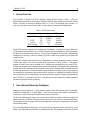
The University of Hawaii (UH) QUick Infrared Camera (QUIRC) utilizes a 1024 1024 pixel
HgCdTe Astronomical Wide Area Infrared Imaging (HAWAII) array produced by Rockwell Science
Center. This array is sensitive to radiation from 1 to 2.5
m. The reimaging optics provide a 1:1
scale, giving the pixel scales listed in Table 1 for the various telescopes and configurations.
Table 1. QUIRC pixel scales
Telescope Optics arcsec/pixel FOV (arcsec)
UH 88-inch f/10 0.1886 193x193
f/31 0.06084 62x62
CFHT f/8 0.150 154x154
0.61-m f/15 0.43 440x440
QUIST 0.25m f/10 1.5 1550x1550
The QUIRC system is comprised of four functional components: (1) the detector, optics, and dewar;
(2)The detector readout electronics; (3) A DSPcontroller; and(4)the instrumentcontrolSparcstation
and fiber optic communications interface. The first three components are physically integrated and
mounted on the telescope, while the fourth is typically located in the observing room and/or the
computer room.
The QUIRC electronics are controlled from a Sparcstation by issuing commands and receiving data
via fiber optic cables. The control program on the Sparcstation is called “qcdcom”. The qcdcom
program is based on the ccdcom program by M. Metzger and was modified for use with QUIRC.
The qcdcom program controls taking exposures and writing data in FITS format to disk, operates the
moving parts of the instrument such as the shutter, filter wheel, and pupil mask, communicates with
the telescope and guider to obtain information and perform mosaics, and provides a script capability
for automatically performing simple observing tasks. qcdcom is a command line interface only and
does not directly provide image display, but can be used with any popular display program that can
read FITS files (e.g. saoimage, Vista, IDL). A link has also been provided to the viewfits program to
automatically display images (see below).
2 Near-Infrared Observing Techniques
Imaging in the near-infrared (1–2.5 m) generally requires more effort than at optical wavelengths,
because the background is so much higher. There are two general data reduction techniques in
common use—both of these require frequent observation of sky fields.
The first data reductionphilosophyis one in which the sky fields are used for subtraction, and the sky
subtracted image is divided by normalized dome flats to remove the variations in quantum efficiency.
The advantage of this technique is that the dome lights have similar color temperature to the typical
sources being studied.
The second data reduction technique is one in which the sky exposures are also used as flats, so the
image is sky subtracted, then divided by a normalized sky flat. This technique often will work better

2
QUIRC User Guide
in cases where the background has been changing rapidly. It may also give better results if the dome
flat was not evenly illuminated(it is difficult to achieve even illuminationat the 0.6m telescope). The
dark should be subtracted from the sky before division. The disadvantages of this technique are that
the sky flat shows the response of the detector to the OH airglow + thermal emission. In particular,
fringing may be present in certain configurations (e.g. 2.2m f/10 1:1), and fringing is something
which should be subtracted, not divided.
Thenumberof badpixelsusuallydictatesaspecial techniqueforobservinginwhichseveralexposures
are made of the field being studied, with each exposure shifted slightly from the others (dithering).
When the images are combined, the bad pixels in one image can be “filled in" with good pixels from
a shifted image. This technique also improves flat-fielding relative to a single long exposure at the
same position.
It is recommended that at the start and end of each night dome flats and darks be taken. The darks
should ideally be exposures of the same length as the object exposures. Even if the darks are not
directly used in the reduction, they will serve to show which pixels have high dark counts so that
these pixels can be included in a bad pixel mask. Dome flats are generally taken as a lights on/lights
off pair. Using this strategy results in a difference image (ON – OFF) which represents the detector’s
flat-field response to a source with color temperature of a few 1000 K, which is roughly the same
temperature as some of the sources being studied.
The shutter is a leaf type shutter, meaning than the center part of the aperture is open slightly
longer than the outside. Recent tests showed significant center-to-edge illumination differences for
integrationtimesless than 1 second. Therefore, short exposures shouldbe avoided, particularly when
exposing dome flats—it is far better to dim the lights with the domelight dimmer switch and use an
exposure of a few seconds than to use the dome lights at full intensity and an exposure which is less
than a second (this can introduce spurious radially varying structure into the flat-field). There is an
uncertainty in the timing of the shutter of the order of 10 millisec. Therefore, short standard star
exposuresshouldalsobe avoided—onthe2.2m,theEliasstandardsmayneed to be slightlydefocused
to allow reasonable exposure times in the broad filters.
At the 2.2m telescope there is a slight rotation in the nominal cassegrain rotator position (270). The
rotation was measured in February 1996 to be 0.883 degrees CCW (e.g., N is rotated 0.883 deg E of
vertical when displayed in the normal way). One could attemptto adjust slightly for this by changing
the rotator position, or adjust for it later during data reduction. If the precise rotation and scale is
importantto the observations, one must measure this carefully during the run since the exact rotation
value is likely to change slightly between runs when the instrument is taken off the telescope and
remounted.
2.1 Detector Linearity, Saturation, Read Noise, Dark Current
Hard saturation of the detector occurs at 50,000 ADU’s. The total gain of the system results in a scale
factor of 1.85 electrons/ADU. Recent tests (2/96) showed the device to be linear to better than 1% for
values up to about 44,000 ADUs. However, the gain and illumination is variable across the array so
care mustbe taken so that parts of the array are not saturatingwhen the average ADU value is getting
close to the non-linear region. The average value should be kept below 40,000 ADUs to ensure that
one is not saturating areas of the array. The average detector dark current is
0.8 electrons/sec, and
the read noise is
15 electrons rms.

October 30, 1997
3
2.2 Dewar Temperature
The dewar nowhas a temperature sensor and heater. For normal operation, the temperaturecontroller
should be used to set the detector temperature to 80.0K. If the controller is not used, drifts can occur
as the telescope is moved, resulting in dark current instabilities in the array. The new array is not
thought to be more sensitive to these effects than the previous detector, but some of the anomalies
previously seen by observers with the original QUIRC detector may have been due to this effect.
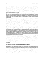
2.3 Camera Sensitivity
The following sensitivity estimates are based on observations of 2 standard stars at the UH 2.2m
telescope on 2/6/96. The Point SRC (source) and Mag/arcsec
2
values are for 1 minute of on-source
integration time, 5
. The point source detection values below assume a PSF of 0.5 arcsec FWHM.
Table 2. QUIRC Sensitivity
UH 2.2m Telescope
Filter Point SRC(Mag) Mag/arcsec
2
Jy/ADU (1 sec)
J 18.6 17.9 1.052e-6
H 17.8 17.1 8.295e-7
K 16.2 15.5 9.622e-7
H+K 18.6 17.9
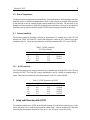
2.3.1 QUIST sensitivity
The following numbers are based on observations of standard stars using QUIST at the UH 0.6m
telescope on 2/9/97. The Point SRC (source) and Mag/asec
2
are for 1 minute of integration time, 5
sigma. The point source detection values below assume a PSF of 2.5 pixels FWHM.
Table 2. QUIRC Sensitivity on QUIST
Filter Point SRC(Mag) Mag/arcsec
2
Jy/ADU (1 sec)
K’ 14.5 16.4 7.644e-5
Hs 14.7 16.6 2.291e-4
Hl 14.3 16.2 2.391e-4
2.12 12.0 15.0 4.563e-6
2.26 12.7 15.5 1.412e-5
3 Setup and Observing with QUIRC
The nominal orientation for QUIRC at the 88-inch telescope is for the black electronics box on the
dewar (the utility box) to point North (toward the control room). Then the resulting FITS data files
written by the program have N up and E to the left (i.e. the (0,0) pixel is in the SE corner).

4
QUIRC User Guide
3.1 Workstation setup
The program is run from a workstation in the control room, currently io (or halley on the 88”).
There is one configuration file thatqcdcom reads upon startupto determinethe telescope, secondary,
and otherinformation. There are four preset configuration filescurrently used, located in the directory
/aux/inst/qconf:
tel_config_06_quirc
tel_config_22_f10_quirc
tel_config_22_f31_quirc
tel_config_cfh_quirc
These files are for the 0.6m, the 88” at
10, the 88” at 31, and CFHT at 8. To install the
proper file, a symbolic link should be made in that directory called tel
config that points to the
appropriate configuration. For example, to set up for the 88” at
10,
% rm /aux/inst/qconf/tel_config
% ln -s tel_config_22_f31_quirc /aux/inst/qconf/tel_config
This step only needs to be done once when the telescope or secondary changes, and should already
be set up properly for the current configuration. Be careful not to delete the configuration files
themselves.
One xterm should be devoted to the camera program. The qcdcom program does not provide an
integrated image display capability. A separate program should be used to display the data. One
option is to use the viewfits program (vf). This is a display program developed by Tony Denault at
the IRTF that displays images and has statistical and graphical analysis features. A link has been
provided from qcdcom to this program that displays images automatically. The program can be run
by typing the following in any window:
%vf&
To display images automatically, one must set the data directory to be the same as where qcdcom is
storing the FITS files. Thisis done by clicking on the “File" buttonand entering the proper path. One
must also issue the command set vfout in qcdcom to enable the link so that data are displayed
automatically. See the section on vf below for more information.
The saoimage program can also be used to display the QUIRC images. The observer should open a
saoimage window on the camera workstation. The command line usually must be edited to read in
the fitsfile. This can be done by pressing the “n" key (for the“new" command)while in the saoimage
window. For example,
-imtool -fits /scr/aug11/q940811.004
would read in file number 4. When in chop mode, qcdcom writes each chop position to a separate
file, and the chop difference to a file ending in “chop" instead of the file number.

October 30, 1997
5
3.2 QCDCOM Setup and Operation
The qcdcom program should be run from the directory where you want your data to be written,
though this can be changed from within qcdcom using the cd command. So execute the following
commands:
% cd /scr/data (or wherever your data should go)
% qcdcom
When qcdcom is started, it initializes communications with the parallel interface, allocate memory
into which to read IR array images, and read enough from the DSP memory to get an idea of the
status of the DSP code. Qcdcom also initializes itself for readout size and binning parameters from
the numbers it reads from the DSP. Since qcdcom runs separately from the DSP computer and saves
its own parameters, qcdcom can be terminated and then restarted without disturbing the DSP.
At startup qcdcom prints a short message identifying the program, and display the filters installed
and the current filter and pupil position. It will also try establishing communicationwith the camera,
and will give a warning if it fails. If the camera has not been initialized after powerup, or if for some
other reason communications have failed, the DSP code will have to be downloaded to the camera.
This is done with the df command. You should do this at the beginning of your observing run to
make sure the correct code is running. The command to download the current standard DSP code is
the following:
df quirc
Occasionally the download will fail if the camera is in some undetermined state, and a reset will need
to be done. The DSP reset is a red button on the white controller box mounted on the dewar. Usually
pressing this once and waiting several seconds before retrying the download will work. Once the
download has completed, the sync command can be used to see if the camera communications are
OK. You can use the sync command at any time to verify that qcdcom and the DSP computer are
talking. Once the main DSP program has been downloaded with the df command, the utility board
program must be downloaded using the following command:
du util
This loads the code that performs the filter wheel and pupil motions.
Next you should set the way files will be named on the disk. Files are named using a prefix with the
frame number appended, thus you should set the prefix using the fp command and reset the running
file number using the fn command (typically to 1 when you start up). For example, to have files
named qrc.001, qrc.002, etc.:
> fp qrc.
>fn1
Note you must specify a trailing dot in the file prefix if you want one.
You will also want to set the exposure parameters using auto at this time. Since you may inherit
parameters from the previous observer, you shouldmake surethey are set to the default values, which
are correct for most observing. One easy way to do this is to use the init command described

6
QUIRC User Guide
below. This puts the program into a mode that will be appropriate for most observing, and will at
least allow one to obtain “normal” images.
The description of the auto command below lists the parameters to be set. The proper defaults are
# resets 1, shutter on, readout on, write on, idle on, double-correlated read on, number of samples 1,
chop off, dummy read on, and dither subtract off. All of these parameters are saved each time they
are changed, so if you have set these parameters previously, this initialization step may be skipped.
At the beginning of your run you will also want to re-initialize the filter wheel to make sure it is
in the correct position. This can be done by issuing the command filter home. This can take
a couple of minutes to complete. If there is any error in this procedure, try again; if the filter
home command does not complete successfully the filter position will be wrong.
The pupil will most likely already be in the proper position; the current pupil position is displayed
when qcdcom starts.
At this point the program is ready to start taking data. Since qcdcom saves almost all of the
setup parameters whenever they are changed, when you quit qcdcom and re-start you can skip the
initialization steps. If qcdcom should exit abnormally (i.e. crash) for any reason, the parameters it
reads in may be old and you may need to set them again. Typically only resetting the file number is
necessary.
3.3 Taking exposures
For each object you are observing you will typically use a sequence of the commands filter,
object,andgo. The following is a quick summary of basic observing commands, but you should
read over the full set of command descriptions (given below) before you begin observing.
The fi command can be used to move the wheel to the proper filter. This command takes a numeric
argument between 1 and 8. The complete list is given in a table below.
The object command is used to set the exposure time and object name. To set up a 180 second
exposure of your favorite region, you might type “object 180 My favorite region”. The
name “My favorite region” will be recorded in the header as the object name.
The go command can then be issued to take the exposure. Qcdcom will reset the array and read
the reset level, open the shutter and take the exposure, read the array again, and write the difference
between the first and second array reads to disk. You can then display this image using your favorite
image display program.
Whenfinishedobserving,thecamerashouldbeleftintheIDLEmode. ThismodehastheDSPperform
a reset every 5 seconds to prevent the array from saturating. This mode is executed automatically
after an integration if the auto idle flag in the qcdcom program is true. Otherwise, it can be started
using the idle command.

October 30, 1997
7
4 Writing Scripts and Taking Mosaics
Any sequence of qcdcom commands can be entered into a text file (using your favorite editor) and
executed by qcdcom. The command to do this is source file, where file is the filename of the
command list. This allows some routine types of observations to be performed automatically, for
example taking a sequence of images in J, H, and K. By entering a sequence of filter move, exposure
time, and go commandsinto a file, taking a JHK sequence can be done with one source command.
Each command is printed along with its file name and line number before it is executed. If some
command in the script fails, execution will stop and the line number where it stopped is printed. A
script may be re-started at a particular line by adding the beginning line as the second argument to
script. Thus “source jhk3 5” will begin execution at line 5 of the file jhk3.
Scripts can be most useful for taking mosaics, by using special commands to move the telescope
and communicate with the guider. If you are taking a sequence of unguided exposures, such as for
standard stars, the telescope may be moved directly; the command to do this is tel aoffset RA
Dec, where RA and Dec are offsets from the base position(88”) or current telescope position (CFHT,
0.6m). These commands can be interspersed with go commands, filter changes, etc. in a script to
perform whatever pattern you wish.
You can also perform “guided” offsets, either directly (CFHT) or through communication with Atlas
(88”). This is done via the tel goffset RA Dec command, which stops the guider, moves the
telescope and guide probe, and turns the guider back on. On the 88" this communicates with Atlas
and MiniOtto over the ethernet to perform the guider movements, and on CFHT commands are sent
over a serial cable to the TCS.
As an example, a potentially useful script is one that takes data for a standard star. This might be a
sequence of exposures in a ditheredpattern (using alternatingtel aoffsetand go commands), followed
by a filter change, followed by another dither pattern, and so forth. Several example scripts may be
found in the home directory of obs/irgroup. Another usefulscriptis one that takes a standard dithered
pattern of a field (e.g. a 13-point diamond). This can be simply a sequence of alternating tel goffset
and go commands, or a multiple-filter sequence.
If you prefer, it is also possible on the 88" to run mosaics from Atlas. To do this, turn pause and
CCD modes off and QUIRC mode on on Atlas. After initiating the mosaic program on Atlas, the
qcdcom tel gnext command tells Atlas to move to the first mosaic pattern positionand waits for
it to finish moving. The go command can then be issued, then another tel gnext causes Atlas to
move to the next mosaic position. This can be repeated until the mosaic is complete, and any other
qcdcom commands (except telescope motion, do not use aoffset!) can be interspersed. Note that
if Atlas encounters an error, an alert box will pop up and Atlas will cease talking to qcdcom until the
alert is cleared. This will most likely cause the script to fail, and the mosaic will need to be re-started
from the middle.
5 Filters and Focusing
There are now two filter wheels in QUIRC with eight positions each. Because two OPEN positions
(position 5 on both wheels) are required and one position (wheel 2 slot 8) holds a polarizer, thirteen

8
QUIRC User Guide
positions are available for filters. These will include the standard broadband filters J, H, K, K ,and
H+K. In addition there will usually be several narrowband and other special purpose filters installed.
Below is a list of the current filters as of the date of this manual. These are subject to change; the
most recent configuration can be obtained by using the fi command in the qcdcom program, or by
checking the QUIRC WWW homepage. The focus offsets for f/10 and f/31 are also given. The
nominal focus positions are 4450 (f/10), 200 (f/31), and with HIPPO they are 5620 (f/10) and
500
(f/31). These are to be used as starting points, the values will shift significantly with temperature,
especially at f/31.
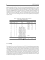
Table 2. QUIRC filters, thicknesses and focus offsets
(Focus setting correlates with
)
2.2-m focus encoder offsets
Setting# Wheel Pos Filter thick (mm) f/10 f/31
1 1 1 J 3.442 +60 +20
2 1 2 H 1.969 +10 +3
3 1 3 K 2.134 +10 +3
414 K
1.080 0 0
5 1 6 H&K dual (1.8
m) 2.794 -20 -6
6 1 7 H2BP23 (2.12
m) 0.914 +2 +1
7 1 8 2260BP60 (2.260
m) 2.794 -20 -6
8 2 1 1560BP120 (1.56
m)
9 2 2 1710BP120 (1.71
m)
10 2 3 1.989BP50 (1.989
m)
11 2 4 1.506/60 (1.506
m)
12 2 6 1.107/50 (1.107
m)
13 2 7 BrGamma (2.166
m) 0.965
14 ... ... LOWFLUX (0.000
m)
ATLAS Dichroic
IN BEAM (
0 75 m) 4 -75 -25
5.1 Focusing
The commandfocus n isan efficient way to focus QUIRC without taking many separate images.
This routine opens the shutter n times between detector readouts to allow recording several focus
images on the array. One can then directly compare the image quality at the different focus settings.
The program pauses after each shutter open/close to allow the focus setting and position of the star
to be changed. The telescope must be moved so that the images of the star do not overlap. See the
qcdcom command section below for more details. There are two advantages to using this procedure.
The first is that one can avoid the overheads with many different images and array readouts. The
second advantage is that all the focus images are in the same image, which makes it easier to compare
the different focus settings to choose the best one.

October 30, 1997
9
5.2 Taking Dark Frames
Sincethereisnoblankpositioninthefilterwheelandtheshutteriswarm,someextracareisrequiredto
obtainreasonabledark frames. Withthe installationofthesecondfilterwheel, a“LOWFLUX" setting
has beenprovided. Thissettingselects twofilters simultaneouslywithincompatablebandpasses, e.g.,
the J filter and Br
(2.16 m). This produces a reasonably low flux condition at the array, limited by
the out-of-band blocking of the filters and leakage around the filter wheels.
Another way to get a dark frame is to move halfway between filters on the wheel to block most of the
emission of the warm shutter. Special commands have been provided for doing darks, and a typical
sequence might be as follows:
> filter 2
> filter DARK
> dark 180 Dark Frame
>go5
> filter BACK
This takes 5 180-second dark frames. The dark command works exactly like the object command,
except that the shutter will not open for the exposure. Note you must use the object command
before your next data exposure, or change the default actionswith auto, or the shutter will not open!
Also note that you should always do only one filter DARK followed by exactly one filter
BACK, always in pairs, otherwise the filter wheel will get lost and require a filter home.Be
careful, there is no indication from the program when this has happened, as there is no encoder on
the filter wheel. Moving the filter wheel between the J and H filters, as in the example, appears to
minimize the thermal radiation from the warm shutter reaching the detector.
6 Cold Restart
If the power should fail or the DSP computer should need to be reset, the following sequence of
commands should be issued:
>sy
> df quirc
> du util
If this happened during a filter wheel move or pupil mask motion, you will need to reset that with the
filter home or pupil home commands,respectively. Notethatthe pupilmaskre-initialization
can take a long time (up to 30 minutes!) and is a bit tricky. Because of this, observers should never
move the pupil mask unless you are sure it is absolutely necessary–it usually isn’t.
7 Running VF to display data
The VF program is a tool for displayingFITS files, written by Tony Denault for the IRTF. See the VF
manual for detailed information on the program and its capabilities. Its interaction with the qcdcom

10
QUIRC User Guide
program is described here.
7.1 Setting up
The setup file .vf-init has been installed in the home directory of the user obs. If running from
a different user name, you must have this file in your home directory, as well as the *.cm files and
ps
proc. The program can be run by typing the following in any window:
%vf&
To display images automatically, one must set the data directory to be the same as where qcdcom is
storing the FITS files. Thisis done by clicking on the “File" buttonand entering the proper path. One
must also issue the command set vfout in qcdcom to enable the link so that data are displayed
automatically.
7.2 Image display options
The qcdcom program is set up to display the last file written. The images are displayed to the “Big
Image" buffer, called E or B4 in the program. If the program is in chop or dither subtract mode, it
displays the .chop image. If not, the last normal data file is displayed. The magnification of .5x
will display the entire QUIRC image.
One useful feature is that if the data are not being saved and vfout is on, the data file is still written
to the .chop image and displayed in vf. Therefore the observer can take focus frames, acquire and
center the object, etc., without saving all the images as separate data files. This avoids filling the disk
with useless files.
7.3 Quick VF tips
The VF manual has a complete listing of the capabilities of the program. Listed below are a few
quick tips to get started:
After starting the program, click on the “E" button below the four canvases to display the big image
canvas. The grayscale levels can be set to Auto or Fixed and the max and min set manually. The
stretch can then be adjusted by pressing the right mouse button and moving it around the image,
similar to saoimage.
The“Zoom onObjBox"isa usefulfeature to zoominonasource. Aftertheimagehasbeendisplayed,
make a box around it by moving to the lower left corner and press & hold the middle mouse button,
then move to the upper right corner and release. Then left click on the “Zoom on ObjBox" button
and it will magnify it. Click on the .5x button to go back to full scale. When zoomed in, you can
use the LineCut display mode to show the profile in the X and Y directions. Click on “Box" and turn
AutoScale on to display the cuts through the box in the X and Y directions. You may need to adjust
slightly the X and Y axis to go through the center of the source.

October 30, 1997
11
The TCS coordinate window (under Options) can be used to center a source or move it around the
array at the 88-inch. The plate scale defaults to the f/10 scale (0.1886 arcsec/pix), for the f/31 scale it
is 0.0608 arcsec/pix. First move to the source and press the “f" key, it will grab the pixel location as
the “From" coordinates (you may need to click left with the mouse on the source before hitting the F
key). Then move to the center or wherever and hit the “t" key to grab the “To" location. Alternatively,
the from and to positionscan be defined by holding the shift key and clickingand dragging the middle
mouse button. Once the positions have been defined, click on “calculate offset" and then on “Offset
TCS" to actually move the telescope (the 88-inch). You can also just read the offsets and move the
telescope by hand.
8 QCDCOM commands
This is a description of the available QCDCOM commands. Any unique abbreviation will work, and
qcdcom will prompt you if you enter an ambiguous command. When you first start qcdcom you
should be aware of two self explanatory commands:
help Help help lists the currently recognized commands. Angle brackets indicate
arguments, and square brackets indicate optional arguments.
quit Quit quit terminates qcdcom. Control-D will also do this.
8.1 DSP initializationcommands
In general, you will need to initialize the DSP processor in the Leach electronics after power-up or
after a DSP reset, because its cold-reset state is not appropriate for running the instrument. In order
to do this you need to read a file of compiled DSP code, and then download it to the DSP. (Note that
DSP assembler code in a .asm file is compiled by the a56 compiler into binary code in a .lod file. For
example, a56 quircop1 will read quircop1.asm and write quircop1.lod.)
Note that while you may see several different versions of the code for QUIRC in the dsp directory,
you can always find the current version of the code as quirc.lod. (It is maintained as a symbolic
link to the working code.) Thus to download the current version of the code, after a power cycle
or DSP computer reset, you can always use df quirc to load correct code. Remember that it
is not necessary (and even undesirable) to download code when qcdcom is restarted. Quitting and
re-starting qcdcom in itself has no effect on the on-board DSP computer, which runs independently.
df file Read and download DSP code
df is a combination of ll and dl, and is the normal command to use for sending
code to the DSP. It will fill in a .lod extension if it is missing, and it will look in
directories according to the environment variable LODPATH, which can be set to a list
of directories separated by colons. Thus, the visitor account has been provided with:
setenv LODPATH .:/aux/inst/dsp:./mydspcode
Example: df quirc

12
QUIRC User Guide
ll file Read DSP code .lod file
ll reads a DSP code binary file into the Sparcstation memory.
dl Download DSP code
dl sends the DSP code to the DSP electronics, and then causes the DSP to start
executing this code. dl also asks the DSP to recalibrate its A/D converter, which takes
about 2 seconds.
du file Download Utility board code
du loads the utility board code. This command should be run after the DSP has been
initilalized with the dl or df commands above. The utility board code is necessary to
perform filter wheel and pupil slide motions.
Example: du util
8.2 Commands for setting up and taking exposures
Qcdcom takes exposures and writes data files according to various parameters which you can set.
The basic sequence that qcdcom follows is to
1. Reset the chip
2. Do dummy read to stabilize array
3. Perform first data read of double-correlation pair, store image in memory
4. Turn off output amplifiers
5. Open the shutter and wait for a predetermined exposure time
6. Close the shutter
7. Turn on output amplifiers
8. Do dummy read to stabilize array
9. Perform second data read, subtract the first from it, store in memory
10. Write the contents of memory into a FITS format data file
11. Put the controller into reset idle mode
These actions are performed by the fundamental command go, which is described below. First, the
commands which tailor the sequence followed by go are given.
Not all of these steps may be taken, and the actual sequence followed depends on how the automatic
actions are set, as described below. There are a number of ways to set the parameters which govern
what qcdcom does. Several commands are available which can be used to set integration time, object
name, object type (a FITS header item), and default automatic actions. None of these does anything
more than setting parameters to be used later—only go takes an exposure.

October 30, 1997
13
object time name Setup for object
object prepares qcdcom to take an exposure of a general target. You can specify
integration time as the first argument and an object name as the second. The object
command sets the automatic actions: # of resets: 1, shutter on, readout on.
Example: object 300 N3031 (set integration time to 300 sec and object name
to N3031) Example: object 0.18 (set integration time to 0.18 sec )
auto set automatic action
auto goes through the choices for the automatic actions, and allows you to set each.
You should not normally need to use auto directly, since you can use the object,
dark, etc. commandsfor most normal exposures. It is provided for those who need
to do fancy things. The automatic actions are:
#reset: n Number of times to reset the chip before starting the exposure. Should
usually be set to 1.
Shutter on/off Controls whether the shutter should be opened for the exposure.
Usually set to ON, otherwise no flux from sky gets to detector.
Readout on/off Controls whether the chip should be read out at the end of the
exposure. Usually ON.
Write on/off Controls whether a FITS file should be written after the chip is read
out. UsuallyON to save data. Thiscan also be set usingthe commandset save.
idle on/off If on, at the end of a readout the chip is placed in a continuous reset, or
idle, mode.
double correlated read on/off Controls whether the device is read out before and
after the shutter opening, or only after. If reading before and after, the difference
between the two are taken, and this difference is written to the FITS file. Double
correlated read ON is the normal operating mode.
Number of samples n controlshow many frames to co-add in the double correlated
read. For each exposure, the chip will be reset and read n times before opening the
shutter, and read n times after the shutter closes. Usually set to 1.
chop on/off Controls whether a beamswitched pair of integrations is performed for
each go command. If at the UH 88-inch, the beamswitch is done automatically.
Use with caution. The on and off source frames are differenced and the result is
storedin a file with the name constructed from the data file nameplus “chop” added
instead of the file number. This file is overwritten every time a new chop is done.
dummy read on/off In order to get the array into a stable mode, a “dummy read" is
done immediatelybefore the read that is saved as data. This occurs both before and
after the integration. This should be turned on for normal operation. The "dummy
read" may not be necessary for broad-band imaging. Not using a dummy read
causes the first three lines of each quadrant to be slightly unstable with respect to
the rest of the array on the level of 5-10 ADU’s. For narrow-band imaging, this
may be a significant effect. The conservative approach is to use the dummy read.
This will add 5 seconds overhead to each image.

14
QUIRC User Guide
dither subtract on/off This option, when turned on, will subtract the previous image
from the current one and store the result in a file witha “chop" added to the normal
data file name instead of the file number. The name is the same as the chop mode
described above. This is often useful when dithering on a faint source that cannot
be seen without subtracting the sky/array background from the image.
For experienced users: note that if you want to use auto from a script, you can specify
the complete set of parameters, in the order above, as numeric arguments. Be careful not
to skip any, and use 1 for on and 0 for off.
clear num Clear (reset) array
clear resets the detector num times, default 1. If you have CTRL-C’d out of an
integration, you should do a clear to reset the device and qcdcom. If you do not use
clear after CTRL-C, on typing the next go qcdcom will assume you want to continuethe
previous exposure.
comment text Adds a comment to the obs.log file, and to the FITS header of the
image file. This is added only to the next observation header, then it is cleared.
et seconds Set exposure time
et sets the exposure time. Any floating point value is accepted; the accuracy of the
exposure timing is somewhat better than 0.01 second, but it is ultimately limited by the
mechanics of the shutter. et uses Unix to compute the exposure time, and an exposure
which is based on Unix timing can be interrupted. Some care is taken to make sure that
the unix timed exposures are correct, but the machine running qcdcom is heavily loaded
it is possible for the shutter to stay open slightly longer. The exposure time recorded in
the header, however, will reflect the true amount of time the shutter was open.
filter num command Set filter
This command selects the filter setting. If no filter setting number is given, the list
of installed filters and the current setting is given. To specify a filter setting, its number
is given. If it is different than the current filter setting, the wheels are moved to the new
position. Note that for a filter wheel setting, both wheel positions are specified and the
movements are done simultaneously. See the fw command description below if other
filter wheel motions are required. To reinitialize the filter wheels, the command fi
home is used. One can use fi home1 or fi home2 to reinitializeonly one particular
wheel. To use the polarizer (wheel 2 position 8) with one of the filters in wheel 1, one
adds the word “pol" after the number requested, e.g. fi 1 pol will select filter setting
1 and the polarizer instead of the OPEN position in wheel 2. Since the polarizer is in the
second wheel, it can only be used with filters that are in wheel #1 (filter settings 1-7).
The command fi DARK will move the filter 1/2filter stepbackward between filters
to aid in taking a dark frame if necessary. Note that there is now a LOWFLUX filter
setting which should give a reasonable dark frame. The command fi BACK inverts the
DARK commandand restores the wheel to its previous position. Be very careful to issue
BACK when finished taking dark frames, otherwise the filter wheel position will be lost.
If this happens, more than one DARK or BACK command in a row or not in pairs are
issued, or the filter wheel motionfails for any reason, issue a filter home command
to re-calibrate the filter wheel positions. It is well worth the extra time.

October 30, 1997
15
fw wheel# position Set filter wheel to position
Set the specified filter wheel (1 or 2) to a specific position (1 through 8). For
example, one would give the command fw 2 3 to move filter wheel 2 to position
number 3. This command is normally not used, the fi command (see above) is used
to set the standard filter positions. However, this command could be used to set some
non-standard combination of filters, such as the K filter and a narrowband filter.
fn fileno Set running file number
Qcdcom writes files of the form filename.xxx, where xxx is a file number. fn
allows you to specify the file number. Qcdcom uses the current file number as a prompt,
and automatically increments the file number as each file is written.
focus number Do focus image
focus performs a focus integration, with the number parameter being the number
of focus integrations in one detector readout. The shutter is open and closed “number"
times, pausing between each integration for a focus change and movement of the object.
fp prefix Set file prefix
fp allows you to specify what the output file name will be. Qcdcom expects to write
a file of the form prefixNNN, where NNN is the frame number. fp is how you specify
prefix. Note that if you want a decimal point as a separator you must specify it.
Qcdcom’s default for a file prefix is qrc..
Example: fp q940811.
go num Start exposure
Go isthe commandtotake an exposure. As described above, according to the param-
eters which are set, go may reset the chip, open the shutter and close it a predetermined
time later, read out the data into memory, write the data to disk, and set the controller
into idle mode. An exposure which has been started with go and Unix timing (et) can
be interrupted by control-C. This will close the shutter and return you to the qcdcom
command level. You can then alter parameters while you are in the paused mode. For
example, you can change the exposure time with et, or the eventual output file name
with fp or fn. You can set or unset automatic flags to specify what go will do when it
finishes. If you want to continue the exposure, you can reissue a go command. If you
want to read out the device, you can issue an rc command. If you want to abort the
exposure, use the clear command. You can take multiple identical exposures with the
num argument.
idle Put camera in idle mode
idle starts an infinite loop of resetting the detector every 5 seconds. It is a good idea
to leave the system in this statewhennot observing,so that thedetector doesnot saturate.
If the auto idle mode is set, the camera is put into idle mode after every exposure.
init Reset all “auto” parameters to defaults
This command initializes all the program parameters to a default state that is appro-
priate for most observing. One can use this as an easy way to reset the program when
starting out after another observer has been using Quirc.

16
QUIRC User Guide
name objname Set object name
name is used to set the object name which will be written to the FITS header.
pupil num command Set pupil position
This commandsets the pupil position. If no pupil number is given, a list of available
pupils are given and the current pupil position is shown. If the pupil number is different
from the current, the pupil slide is moved to the new position. Note that the positionsare
separated by 7500 steps of the motor, so it takes many minutesto move to a new position.
The pupil can be moved to the reference position by typing pu home.
The command pu switch will report on the position of the pupil/filter wheel 2
switch. The same motor controller is used for these motors, and only one can be in
operation at any time, selected by the switch on the utility (black) box on the QUIRC
dewar. This command tells whether it is in the PUPIL or FILTER position.
For fine adjustment of the pupil position, the commands pu FO and pu BA will
move the pupil 10 or -10 steps, respectively. This can be used to move the pupil by small
amounts near its nominal position.
rc Xnx Xny read array
rc readsout the array, and ifthe auto-write flag is set, rcwill writetheresultingimage
to a disk file.
set param n Set parameter
Certain program parameters can be set or unset with this command. To set a param-
eter, for example “save", one issues the command set save. To unset, the command
set nosave is used. Alternatively, one can type set save 1 and set save 0
to turn it on or off. Below are the available parameters:
clobber – If on, existing files will be automatically overwritten. If off, the program
will ask for confirmation from the user before overwriting files.
chop – Turns chopping on or off. Also can be set via the auto command.
beep –Causes theprogram to beep after each detectorreadout, andotheroperations.
Can be annoying.
vfout – Directs qcdcom to send commands to vf to display the most recent image.
save – Turns auto save on or off. Also can be set via the auto command.
longshut – Sets the long shutter mode. In this mode, the shutter is opened before
the initial reset of the observation is done, and keeps it open until after the final
read is completed. Because of the array read time, the minimum integration time
is about 11 seconds. This mode can be used if one wants to avoid the background
from the warm shutter when taking exposures of faint fields. Note that if any bright
objects are in the field the detector will likely saturate on those sources.
shutter (open|close) Commands the specified shutter action.
status Show status
status shows the current parameters.

October 30, 1997
17
sound Toggle fancy sounds
Qcdcomwillusedistinctive sounds for variousoperations. If you don’t want to listen
to them you can turn them off with the sound command.
synch “Ping” the DSP by sending it data and asking it to send it back. This is useful
to check to see whether the controller is alive and receiving commands properly from
qcdcom, or if the electronics may need a hardware reset.
wf file Write FITS file
Qcdcom reads out the array into memory, and maintains the image there. The wf
command puts together a FITS header for the image and writes it to a disk file. If the
write fails (for example because the disk is full) wf will abort, but the program will keep
the datainmemoryand youcansave yourdataafter rectifying theproblem that prevented
the write.
8.3 Diagnostic commands
These commands are for diagnostic purposes only, and should not be used for normal observing.
They include commands to test the data link and provide direct access to the DSP computer.
hall nloop Read Hall sensors
read the Hall effect sensors nloop times. The filter wheel 1 sensor is displayed, and
depending on the position of the switch, either the pupil or filter wheel 2 sensor. This is
usefulwhen adustingthe offset level of the amplifiersbetween warm and cold conditions
to get the sensors within the range of the A/D’s.
diag rm M:addr -addr Read DSP mem
rm reads the P:, X:, or Y: memory of the DSP chip. All in hex (alas?).
diag wm M:Xaddr Xval Write DSP mem
rm writes values to the P:, X:, or Y: memory of the DSP chip. Also in hex (also
alas?).
diag ii Re-init I/O
ii reinitializes the I/O with the parallel interface and fiber-optics parallel interface
electronics.
diag ic Init camera
ic instructs the DSP cpu to reload its memory from ROM. This has the effect of
destroying any downloaded code and replacing it with the basic monitor program which
has code for a different detector.
diag oc cmd Issue a command to the DSP interpreter
oc sends a three letter mnemonic command to the DSP cpu. Most of the useful
commands are sent by various qcdcom commands automatically, but some commands
can only be sent via oc.

18
QUIRC User Guide
Examples:
oc IDL put controller in idle mode
oc RDC perform detector read
diag l1 cnt r|c data 4MHz loopback test mode.
Test fiber opticinterface in hardware loopbackmode. Receiver iswired for operation
at 4MHz, and a fiber is connected directly between the receiver and transmitter. This
test runs cnt loops of 65536 words each, with values 0 through 0xFFFF. If the c option is
specified, then data is a value (in hex) to be sent repeatedly. If the r option is specified,
then data is used as a seed for a random number generator and 65536 words of random
data are sent per loop.
diag l3 cnt r|c data Timing board loopback test
Loopback test with timing board in place. Must have code downloaded or be in cold
reset state. Similar to L1 in other respects.
diag l4 cnt data read loop test
Test interface by repeatedly performing the RDC command and looking for data. If
the proper number of data words are not received, an error message is generated and the
program counts the errors.
diag l5 cnt r|c data Timing board loopback test: high 16
Same as L3, but tests high 16 bits of data word. Must have code downloaded that
supports the THI command (e.g. quircop1.asm)
-
 1
1
-
 2
2
-
 3
3
-
 4
4
-
 5
5
-
 6
6
-
 7
7
-
 8
8
-
 9
9
-
 10
10
-
 11
11
-
 12
12
-
 13
13
-
 14
14
-
 15
15
-
 16
16
-
 17
17
-
 18
18
-
 19
19
-
 20
20


Sigma QUick Infrared Camera User manual
- Category
- Bridge cameras
- Type
- User manual
Ask a question and I''ll find the answer in the document
Finding information in a document is now easier with AI
Other documents
-
König SEC-DUMMYCAM65 Datasheet
-
ESAB Linde CE-2A Cryosurgery Equipment Assembly Instruction
-
 Moravian Instruments G3 Series Operating instructions
-
Polaroid ccd camera User manual
-
-
Orion PARSEC 10100C User manual
-
-
-
 SBIG ST-402ME Operating instructions
-
 Starlight Xpress 100-0069 User manual


