Patton electronic 2020P User manual
- Category
- Networking
- Type
- User manual

INTERFACE CONVERTER, V.24 TO V.35
2020P
(CTS IC-V.24/V.35-M-34)
INSTALLATION AND OPERATIONS MANUAL
Doc #: 147001UA
Part #: 07M2020P-A
May 11, 2000
B
An ISO-9001
Certified Company
Copyright© 2000 Patton Electronics Co., All Rights Reserved

147001UA
i
Table of Contents
CHAPTER 1 - Operation
CHAPTER 2 - SETUP AND INSTALLATION
Installation....................................................................................2-1
Selection of DTE/DCE .................................................................2-1
Equipment Grounding..................................................................2-2
LED Indicators .............................................................................2-2
Factory Test Straps......................................................................2-2
APPENDIX
TECHNICAL SPECIFICATIONS ................................................ A-1
V.35 Interface Pins Supported.................................................... A-2
V.24 Interface Pins Supported.................................................... A-2

147001UA
ii
Copyright© 2000 Patton Electronics Co., All Rights Reserved
PROPRIETARY NOTICE
The information contained herein is proprietary and confidential to Patton
Electronics Co. Any
reproduction or redistribution of this publication, in whole or in part, is expressly prohibited unless written
authorization is given by Patton
Electronics Co.
WARRANTY NOTICE
WARRANTIES: Patton
Electronics Co. (hereafter referred to as Patton) warrants that its equipment is
free from any defects in materials and workmanship. The warranty period shall be two years from the
date of shipment of equipment. Patton’s sole obligation under its warranty is limited to the repair or
replacement of the defective equipment, provided it is returned to Patton, transportation prepaid, within
a reasonable period. This warranty will not extend to equipment subjected to accident, misuse,
alterations or repair not made by Patton or authorized by Patton in writing.
PUBLICATION NOTICE
This manual has been compiled and checked for accuracy. The information in this manual does not
constitute a warranty of performance. Patton reserves the right to revise this publication and make
changes from time to time in the content thereof. Patton assumes no liability for losses incurred as a
result of out-of-date or incorrect information contained in this manual.
RADIO AND TV INTERFERENCE
The Patton MSDs generate and use radio frequency energy, and if not installed and used properly—that
is, in strict accordance with the manufacturer’s instructions—may cause interference to radio and
television reception. The Patton MSDs have been tested and found to comply with the limits for Class A
computing devices in accordance with the specifications in Subpart J of Part 15 of FCC rules, which are
designed to provide reasonable protection from such interference in a commercial installation.
However, there is no guarantee that interference will not occur in a particular installation. If the Patton
MSDs do cause interference to radio or television reception, which can be determined by disconnecting
the cables, the user is encouraged to try to correct the interference by one or more of the following
measures: moving the computing equipment away from the receiver, re-orienting the receiving antenna,
and/or plugging the receiving equipment into a different AC outlet (such that the computing equipment
and receiver are on different branches).
CE NOTICE
The CE symbol on your Patton Electronics equipment indicates that it is in compliance with the
electromagnetic Compatibility (EMC) directive and the Low Voltage Directive (LVD) of the European
Union (EU). A Certificate of Compliance is available by contacting Technical Support.
SERVICE
All warranty and non-warranty repairs must be returned freight prepaid and insured to Patton Electron-
ics. All returns must have a Return Materials Authorization number on the outside of the shipping
container. This number may be obtained from Patton Electronics Technical Support at:
tel: (301) 975-1007;
email: [email protected];
or, www: http://www.patton.com.
NOTE: Packages received without an RMA number will not be accepted.
Patton Electronics’ technical staff is also available to answer any questions that might arise concerning
the installation or use of your Patton MSDs. Technical Support hours: 8AM to 5PM EST, Monday
through Friday.

147001UA
CHAPTER 1 - Operation
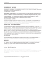
The Patton 2020P (IC-V.24/V.35) is a RS-232 to V.35 interface con-
verter. The interface converter operates bi-directionally. DCE / DTE
selection of the ports permits interfacing RS-232 terminals to V.35
Modems or RS-232 Modems to V.35 terminals. This adapter is ideal for
High Speed Group Band Modems since it can operate at 56Kbps or
faster (Up to 128Kbps).
Because the operator can configure the interface converter to be RS-232
on the terminal port and V.35 on the Modem Port, or V.35 on the terminal
port and RS-232 on the Modem Port, the 2020P (IC-V.24/V.35) can
satisfy either interface conversion requirement. Devices can be sepa-
rated up to 600 feet away from the 2020P (IC-V.24/V.35) on the V.35
side and RS-232 devices can be extended up to 50 feet away. The unit
is supplied with a female DB-25 connector on the RS-232 port and a
female 34 pin connector on the CCITT V.35 port.
The Patton 2020P (IC-V.24/V.35) is housed in a sturdy aluminum enclo-
sure and has an internal 110/220VAC switch selectable power supply.
The Interface Converter will also fit into the 1010R16/P/UI (MCS-16C)
card rack assembly, providing a convienent means to us the cards in a
data center.
The unit has MET, c-MET and CE approvals and can operate on stan-
dard power found in most countries.
1-1
Typical Application
V.35 Host
Processor
V.24 Terminal
IC-V.24/V.35

147001UA
2-1
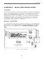
CHAPTER 2 - SETUP AND INSTALLATION
Installation
Set switches to match the required configurations based on the diagrams
below. The cabling between each device and the 2020P (IC-V.24/V.35)
must be terminated with male connectors. J1 is the RS-232 / V.24
interface and J2 is the V.35 interface. The IEC connector is provided to
interface to the power plug required in the country of use. Insure the
110/220VAC switch is set correctly for the line voltage in use prior to
appling power to the 2020P (IC-V.24/V.35).
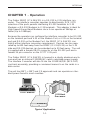
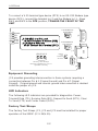
Selection of DTE/DCE
To connect an RS-232 terminal type device (DTE) to a V.35 Modem type
device (DCE), connect the terminal to J1 and the Modem to J2. Move
SW1 and SW2, to the DCE position, TOWARD THE REAR OF THE
UNIT.
J1
JP3JP2
J4
JP1
J2
JP4
CTS
Power
TD
DCD
RD
J3
SW2
SW1
RTS
V.24 INTERFACE
V.24 INTERFACE
DCE
DTE
4
3
2
1
DCE
DTE
Factory Test Straps
Must be Installed for Unit To
Operate Correctly
RS-232
V.35
J1 (RS-232) Is a DCE, and
MUST Connect to a Terminal (DTE)
J2 (V.35)Is a DTE, and
MUST Connect to a Modem (DCE)
Signal
to
Chassis
Grou nd
(Factory Default Setting)

147001UA
2-2
To connect a V.35 terminal type device (DTE) to an RS-232 Modem type
device (DCE), connect the terminal to J2 and the Modem to J1. Move
SW1 and SW2 to the DTE position, TOWARD THE FRONT OF THE
UNIT.
J1
JP3JP2
J4
JP1
J2
JP4
CTS
Power
TD
DCD
RD
J3
SW2
SW1
RTS
V.24 INTERFACE
V.24 INTERFACE
DCE
DTE
4
3
2
1
DCE
DTE
Factory Test Straps
Must be Installed for Unit To
Operate Correctly
RS-232
V.35
J1 (RS-232) Is a DTE, and
MUST Connect to a Modem (DCE)
J2 (V.35)Is a DCE, and
MUST Connect to a Terminal (DTE)
Signal
to
Chassis
Grou nd
Equipment Grounding
JP4 provides grounding interconnection in those systems requiring a
connection between Pin # 1 (Frame Ground) and Pin # 7 (Signal
Ground). If signal ground and chassis ground interconnection is desired
install the jumper on JP4.
LED Indicators
The Following LED indicators are provided for diagnostics: Power,
Transmit Data (TD), Receive Data (RD), Request to Send (RTS), Clear
To Send (CTS) and Carrier Detect (DCD).
Factory Test Straps
The Factory Test Straps JP1, JP2 and JP3 must be installed for proper
operation of the 2020P (IC-V.24/V.35).

147001UA
APPENDIX
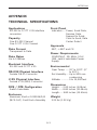
TECHNICAL SPECIFICATIONS
A-1
Front Panel
Indicators:... Power, Send Data,
Receive Data,
Request to Send,
Clear to Send, Data
Carrier Detect
Approvals
MET, c-MET and CE
Power Requirements
110/220VAC, 50/ 60Hz, 0.16/
.08A, switch selectable Power
Supply
Environmental
Oper Temp: ..... 32° to 122°F (0°
to 50°C)
Rel Humidity:... Up to 90% non-
condensing
Altitude: ........... 0 to 10,000 feet
Dimensions
Height: .... 2.00 inches (5.08cm)
Width: ..... 8.80 inches (21.08cm)
Length: ... 9.80 inches (15.49cm)
Weight
2.25 lbs (1.02 Kg)
Applications
RS-232 to CCITT V.35 interface
conversion
Capacity
One RS-232 Channel
One CCITT V.35 Channel
Data Format
Transparent to Data
Data Rates
Up to 128Kbps
Electrical Interface
RS-232 and CCITT V.35
RS-232 Physical Interface
Female DB-25 Connector
V.35 Physical Interface
Female V.35 (M34) Connector
DCE / DTE Configuration
Switch Selectable
Enclosure
Aluminum Shell or 1010R16/P/UI
(MCS-16C) Card Rack Assembly

147001UA
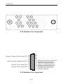
V.24 Interface Pins Supported
A-2
V.35 Interface Pins Supported
1
2
3
4
5
6
7
8
9
10
11
12
13
14
15
16
17
18
19
20
21
22
23
24
25
Shield (common)
Transmit Data (from DTE)
Receive Data (from DCE)
Request to Send (from DTE)
Clear To Send (from DCE)
Data Set Ready (from DCE)
Si
g
nal Ground (common)
Data Carrier Detect (from DCE)
Transmit Clock (from DCE)
Receive Clock (from DCE)
Data Terminal Ready (from DTE)
External Transmit Clock (from DTE)
Z DD JJ
BB FF LL
CC HH MM
EE KKM
K
B
SG
F
CD
L R
RD(A)
V
RT(A)
D
CTS
J N T
RD(B)
A
FG
E
DSR
P
TD(A)
C
RTS
H
DTR
S
TD(B)
W
ETT(B)
AA
TT(B)
U
ETT(A)
Y
TT(A)
RT(B)
X
NN

B
Sales: 301-975-1000 Support: 301-975-1007
Web Address: http://www.patton.com
7622 Rickenbacker Drive
Gaithersburg, MD 20879
-
 1
1
-
 2
2
-
 3
3
-
 4
4
-
 5
5
-
 6
6
-
 7
7
-
 8
8
-
 9
9


Patton electronic 2020P User manual
- Category
- Networking
- Type
- User manual
Ask a question and I''ll find the answer in the document
Finding information in a document is now easier with AI
Related papers
-
Patton electronic TV Converter Box IC-V.24 User manual
-
Patton electronics TV Converter Box IC-V.24 User manual
-
-
-
-
-
-
-
-