Page is loading ...

Instruction Manual
Meade Model 4504
4.5" (114mm) Equatorial Reflecting Telescope
With Starfinder Electronic Hand Controller
ENTER
GO TO
MO
DE
MEADE
ENTER
GO TO
MO
DE
SPEE
D
?
S
T
A
R
F
IN
D
E
R
Meade Instruments Corporation

WARNING
NEVER USE A MEADE
®
TELESCOPE TO LOOK AT THE SUN!
LOOKING AT OR NEAR THE SUN WILL CAUSE INSTANT AND
IRREVERSIBLE DAMAGE TO YOUR EYE. EYE DAMAGE IS OFTEN
PAINLESS, SO THERE IS NO WARNING TO THE OBSERVER THAT
DAMAGE HAS OCCURRED UNTIL IT IS TOO LATE. DO NOT POINT
THE TELESCOPE OR ITS VIEWFINDER AT OR NEAR THE SUN. DO
NOT LOOK THROUGH THE TELESCOPE OR ITS VIEWFINDER AS IT
IS MOVING.
CHILDREN SHOULD ALWAYS HAVE ADULT
SUPERVISION WHILE OBSERVING.
How This Manual is Organized
This manual is divided into three major sections.
Part One, "The Basics," presents several "Lessons" that will teach you how to
assemble and use your telescope and Starfinder. If you follow all the Lessons in this
section, you will become familiar with the basic operation of your telescope and the
Starfinder handbox by the end of Part One. This section covers the following proce-
dures:
Lesson 1: Unpacking and Assembly.
How to unpack and assemble the basic telescope and tripod unit.
Lesson 2: Balancing the Telescope.
How to balance the telescope.
Lesson 3: Aligning the Viewfinder.
How to align the viewfinder and insert the eyepiece into the focuser.
Lesson 4: Observing by Moving the Telescope Manually.
How to focus an eyepiece. How to move your telescope manually to make
observations.
Lesson 5: Observing using Starfinder's Arrow keys.
How to install the motor drives. How to change the slew speeds. How to
observe using Starfinder's Arrow keys.
Lesson 6: Tracking Objects.
How to Polar align your telescope. How to observe using automatic tracking.
Lesson 7: Observing using Starfinder's Go To Capabilities.
How to initialize Starfinder and train the drive. How to move around in
Starfinder's menus. How to observe using Starfinder and how to take a
Guided Tour of the night sky.
Part Two, "Starfinder's Controls and Menus," provides more information about
Starfinder's databases and menus.
Part Three, "Caring for Your Telescope," provides information that explains how to
properly maintain your telescope.
The Appendices provide advanced information about your telescope, explain how
objects move through the skies, and teach how to locate objects not listed in the
Starfinder database.
® The name "Meade" and the Meade logo are trademarks registered with the U.S. Patent Office and in principal countries
throughout the world. All rights reserved.
© 2000 Meade Instruments Corporation

page 3
TABLE OF CONTENTS
PART ONE: The Basics
Lesson 1: Unpacking and Assembly ....................................................................5
How to Assemble Your Telescope ......................................................................8
Lesson 2: Balancing the Telescope ....................................................................10
Lesson 3: Aligning the Viewfinder ......................................................................10
Lesson 4: Observing by Moving the Telescope Manually ..................................11
Observe the World Around You........................................................................13
Lesson 5: Using Starfinder's Arrow Keys ............................................................13
Motor Drive System and Starfinder Handbox Installation ................................13
Activate the Arrow Keys ..................................................................................14
Slew Speeds ....................................................................................................14
Observe the Moon............................................................................................15
Lesson 6: Tracking Objects ................................................................................15
To Polar Align the Telescope ............................................................................15
Observe a Star Using the Automatic Tracking Feature....................................16
Lesson 7: Using Starfinder's GO TO Capabilities ..............................................16
Moving Through Starfinder's Menus ................................................................16
Initializing Starfinder ........................................................................................17
Training the Drive ............................................................................................19
Align Your Telescope Using Starfinder ............................................................20
Check Mount ....................................................................................................20
Go To Saturn ....................................................................................................21
Using the Guided Tour ....................................................................................21
Some Observation Tips....................................................................................22
PART TWO: Starfinder Controls and Menus
Starfinder Controls ..............................................................................................23
How Starfinder's Menus Work ............................................................................26
Starfinder Navigation Exercise ............................................................................26
Starfinder Menus..................................................................................................28
Object Menu ....................................................................................................28
Event Menu ......................................................................................................29
Glossary Menu ................................................................................................29
Utilities Menu....................................................................................................30
Setup Menu......................................................................................................31
PART THREE: Caring for Your Telescope
Cleaning ..............................................................................................................33
Mount and Tripod Adjustments............................................................................33
Collimation (Alignment) of the Optics..................................................................34
Specifications ....................................................................................................37
Appendix A: Calculating Eyepiece Power ..........................................................38
Appendix B:Terrestrial Viewing, Celestial Movement, & Polar Alignment ..........39
Appendix C: Using Starfinder to Enter Celestial Coordinates ............................42
Appendix D: Helpful Charts ................................................................................43
Appendix E: Basic Astronomy ............................................................................44
Objects in Space ............................................................................................44
A Roadmap to the Stars ..................................................................................46
Star Locator ....................................................................................................46

page 4
1
2
3
4
5
7
8
9
6
10
11
12
13
14
15
16
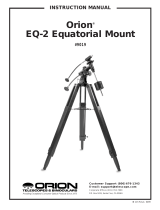
Fig. 1: Parts included in the Meade Model 4504 Giftbox.

page 5
PART ONE: The Basics
LESSON 1: Unpacking and Assembly
As you unpack your telescope, carefully note the following parts. The bolded numbers
in parentheses on this page refer to the photos on page 4.
Telescope Assembly
• Equatorial mount (1) with a pre-attached heavy duty, continuously
adjustable aluminum tripod with leg braces
• 3 tripod leg lock knobs (7)
• Complete optical tube assembly (2) including a 4.5" (114mm) diameter
primary mirror with dust cover and a 0.965" rack-and-pinion focuser with
dust cap
• 2 Cradle rings (3) with attached lock knobs
• Counterweight (8) and counterweight shaft (9)
• 5 x 24 viewfinder with rubber eyecup (5) and viewfinder bracket (10)
Motor Assembly
• Dual electronic motor drive assembly: The Right Ascension (R.A.)
electronic motor drive (12) has a connector for the battery pack, marked
"15v." The Declination (Dec) electronic motor drive (13) has a connector
for the Starfinder handbox, marked "HBX." The motors are connected
with a coiled cord.
• Starfinder handbox (14)
• Battery pack (16) and battery pack case (15) with adhesive backing
Accessories
• 3 Eyepieces (11) (0.965" optical diameter): SR 4mm, H 12.5mm,
H 25mm
• 3x Barlow lens (4)
• Accessory shelf with mounting knob (6)
• 2 Hex Keys, 1.5mm, 5mm (not depicted)
• Astronomical software (not depicted)
You will need a #1 or #2 Phillips screwdriver to assemble this telescope.
Key to the photos, Fig. 1, page 4.
1. Tripod assembly with equatorial mount
2. Optical tube
3. Cradle rings
4. 3x Barlow lens
5. Viewfinder tube
6. Accessory shelf
7. Tripod leg adjustment knobs
8. Counterweight
9. Counterweight shaft
10. Viewfinder bracket
11. Eyepieces
12. R.A. motor drive
13. Dec motor drive
14. Starfinder handbox
15. Battery pack case
16. Battery pack

page 6
1
2
6
5
4
7
8
3
16
10
11
12
9
14
13
15
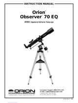
Fig. 2a: The Meade Model 4504 4.5" Equatorial Reflecting Telescope.
1. Equatorial mount
2. Optical tube assembly
3. Cradle rings
4. Viewfinder bracket
5. Viewfinder rubber eyepiece
6. 5 x 24 viewfinder
7. Viewfinder bracket thumbscrews
8. Telescope front dust cover
9. Dec setting circle
10. Counterweight
11. Counterweight shaft
12. Safety washer/thumbscrew
13. Counterweight lock
14. Latitude dial
15. R.A. setting circle
Key to Figures 2a, 2b, and 2c
16. Latitude adjustment knob
17. Focuser, Focus knobs
18. Eyepiece thumbscrew
19. Eyepiece
20. Cradle ring lock knobs
21. Optical tube saddle plate
22. Dec motor drive assembly
23. Latitude lock
24. Azimuth lock
25. R.A. motor drive assembly
26. R.A. lock
27. Dec lock
28. Tripod legs brace support
29. Tripod legs lock knobs
30. Accessory shelf

page 7
23
18
21
22
27
25
19
20
20
24
26
17
28
29
30
28
29
NOTE: The coiled cord that
connects to the two motor
drives has been omitted
from the illustration for the
sake of clarity.
Fig. 2b: The Meade Model 4504 4.5" Equatorial Reflecting Telescope.
Fig. 2c: The Meade Model 4504 4.5" Equatorial Reflecting Telescope.

page 8
How to Assemble Your Telescope
The giftbox contains the optical tube assembly and the tripod with the equatorial
mount. The accessories are located within compartments custom-cut into the styro-
foam block inserts. Refer to Figures 1, 2a, 2b, and 2c for images of the parts and the
overall assembly of the 4504 telescope.
1. Remove the components from the giftbox: Remove and identify the telescope’s
standard equipment. For a listing of parts that are included in the giftbox, see
pages 4 and 5. When removing the tripod from the giftbox, hold the assembly
parallel (horizontal) to the ground or the inner tripod leg extensions will slide out
as they are not locked in place.
2. Install the lock knobs on the tripod: Place the tripod in a horizontal position on
the floor before performing this step. The three tripod lock knobs (7, Fig. 1) have
been removed from the bottom section of each tripod leg to insure safe arrival of
the tripod assembly. To install, thread each tripod lock knob into the threaded hole
located at the right side of each of the three gray-colored castings at the bottom
of each tripod leg. See Fig. 3, and 29, Fig. 2c. Tighten the tripod lock knob to a
"firm feel" only to avoid damage to the tripod caused by overtightening.
3. Stand the tripod: Hold the mount for support (the mount will be loose) and stand
the tripod in a vertical position. Slide the cardboard sheath upward to allow it to
come free when the tripod legs are spread out during the next step.
4. Adjust the tripod legs. Spread the tripod legs as far as they will open, so that the
leg braces (28, Fig. 2c) are taut. Should one of the leg braces slip out of the center
triangle fastener, reposition the brace and slide it back into the triangle fastener.
5. Attach the accessory shelf to the tripod: Remove the mounting knob from the
round accessory shelf (6, Fig. 1). Place the accessory shelf on top of the center
triangle leg brace fastener so that the threaded stud protruding from the bottom of
the shelf (Fig. 4) passes through the hole in the center of the triangle fastener.
Next, thread the mounting knob shaft into the threaded stud. Tighten to a firm feel.
6. Attach the counterweight to the counterweight shaft: Look through the hole in
the counterweight and note the pin blocking the hole (Fig. 5). Tilt the
counterweight slightly and the pin moves out of position, clearing the hole. If the
pin does not move, slightly unscrew the counterweight lock knob (Fig. 5) until the
pin moves. Holding the counterweight (8, Fig. 1) firmly in one hand, tilt the
counterweight to move the pin from the hole and slip the counterweight onto the
counterweight shaft (9, Fig. 1). Tighten the counterweight lock knob (Fig. 5) to a
firm feel.
7. Attach the counterweight assembly to the mount: Attach the counterweight
shaft assembly by supporting the counterweight firmly in one hand, while
threading the counterweight shaft into the base (Fig. 6) of the Declination axis of
the telescope’s equatorial mount with the other. Once firmly attached, loosen the
counterweight lock knob, slide the counterweight to the midpoint of the
counterweight shaft, and re-tighten the lock knob firmly in place (Fig. 5).
NOTE: If the counterweight ever slips, the secured threaded safety
washer/knob (12, Fig. 2a) prevents the counterweight from sliding entirely
off the shaft. The safety washer/knob is pre-attached at the factory. Make
sure that this safety washer/knob always remains in place.
Fig. 3: Tripod leg lock
knob.
Fig. 5: Counterweight
and pin.
Lock
knob
Pin
Fig. 4: Accessory
shelf installation.
Fig. 6: Attach
counterweight
assembly to the
mount.
Thread shaft
into base
Threaded
hole
Sliding
inner leg
Leg lock
knob

page 9
8. Tilt the assembly: Unlock the R.A. lock (26, Fig. 2b) and the Dec lock (27, Fig.
2b) so that the telescope turns freely on both axes. Tilting these axes makes it
easier for you to perform the following steps. Turn the latitude adjustment knob
(16, Fig. 2a) until approximately 1 1/2 inches of thread is showing. This will adjust
the equatorial mount (1, Fig. 2a) to a comfortable angle for tube attachment.
9. Attach the cradle rings to the saddle plate: Remove the attachment screws
from the saddle plate (these screws come attached in the threaded screw holes of
the saddle plate, 1, Fig. 7). Position the threaded screw hole of a cradle ring (4,
Fig. 7) under one of the threaded screw holes of the saddle plate (1, Fig. 7).
Thread one of the attachment screws (5, Fig. 7) through the bottom side of the
cradle ring and through the saddle plate, tightening it with the provided 5mm hex
wrench (so that it is only "fingertight," that is, just loose). Repeat for the second
cradle ring. Remove the cradle ring lock knobs (20, Fig. 2b) and open the cradle
rings.
10. Position optical tube: While firmly holding the optical tube (2, Fig. 2a), position it
onto the cradle rings (3, Fig. 2a) with the mid-point of the optical tube’s length lying
roughly in the center of the saddle plate. Point the tube so that the front end (this
end comes shipped with the dust cover (8, Fig. 2a) over it) is oriented as depicted
in Fig. 2a. Then close the cradle rings (3, Fig. 2a) over the optical tube and loosely
tighten one of the cradle ring lock knobs (20, Fig. 2b) just to hold the tube in place
so you can perform the next step of this procedure.
11. Secure the optical tube: Tighten the cradle ring attachment hex screws to a firm
feel. Then tighten both cradle ring lock knobs (20, Fig. 2b) to a firm feel; do not
overtighten these knobs as you may wish loosen them frequently in order to rotate
the optical tube and position the eyepiece (19, Fig. 2b) in a more comfortable
observing position. This adjustment may be performed several times in one
observing session, if so desired.
12. Attach viewfinder: The viewfinder holder has two restrained screws, i.e., they
cannot be removed from the holder. Position the two screws over the threaded
holes in the viewfinder mounting plate and tighten the screws using a #1 or #2
Phillips screwdriver. It does not matter which way you orient the holder lengthwise.
Loosen the viewfinder's thumbscrews (7, Fig. 2a), but do not remove them.
Remove the viewfinder tube's rubber eyecup (5, Fig. 2a) and slide the tube (6, Fig.
2a) through the bracket rings of the holder. Then center the tube by adjusting the
thumbscrews (7, Fig. 2a) on each bracket ring. Re-attach the eyecup. Make sure
that the viewfinder is oriented so that the rubber eyecup is pointing away from front
end of the optical tube (5, Fig. 2a).
13. Insert the eyepiece: Lift to remove the dust cap from the focuser assembly (17,
Fig. 2b). Put the dust cap aside in a safe place and replace it when you have
finished observing to protect the eyepiece assembly. Loosen the eyepiece
thumbscrews (18, Fig. 2b) and insert the H 25mm eyepiece (Fig. 8) into the
focuser. Tighten the focuser thumbscrews to secure the eyepiece.
14. Adjust the height of the tripod: Adjust the height of the tripod by loosening the
tripod lock knobs (29, Fig. 2c) and extending the sliding inner section of each
tripod leg to the desired length; then tighten each knob. Adjust the tripod to a
height that is comfortable for viewing.
Lesson 5 presents a procedure that explains how to attach the motor drive
assemblies. However, that procedure is not necessary at this time. The following
lesson demonstrates how to balance your telescope.
Fig. 7: Attach cradle
rings to the saddle plate
with attachment screws.
1.
Threaded screw hole
(saddle plate)
2. Saddle plate
3. Cradle ring
4.
Threaded screw hole
(cradle ring)
5. Attachment screw
1
2
1
3
5
4
Fig. 8: Insert eyepiece
into the focuser
assembly.
Eyepiece
Thumb-
screw
Focuser

page 10
LESSON 2: Balancing the Telescope
In order for the telescope to be stable on the tripod and also for it to move smoothly,
it must be balanced. To balance the telescope, you will unlock the Right Ascension or
R.A. lock (26, Fig. 2b and Fig. 9a). When this axis is unlocked, the telescope pivots
more or less horizontally on the mount. This is called the R.A. axis. Later in the pro-
cedure, you will also unlock the Declination or Dec lock (27, Fig. 2b and Fig. 9a).
When unlocked, the telescope pivots more or less vertically on the mount. This is
called the Dec axis. Most of the motion of the telescope takes place by moving about
these two axes, separately or simultaneously. To obtain a fine balance of the tele-
scope, follow the method below:
1. Firmly hold the optical tube secure so that it cannot accidentally swing freely.
Loosen the R.A. lock (26, Fig. 2b). The optical tube now turns freely about the
R.A. axis. Rotate the telescope so that the counterweight shaft (11, Fig. 2a) is
parallel (horizontal) to the ground (Fig. 9b).
2. Unlock the counterweight lock knob (13, Fig. 2a) and slide the counterweight (10,
Fig. 2a) along the counterweight shaft until the telescope remains in one position
without tending to drift down in either direction. Then re-tighten the counterweight
lock knob (13, Fig. 2a), locking the counterweight in position.
3. Again, hold onto the optical tube so that it cannot accidentally swing freely. Lock
the R.A. lock (26, Fig. 2b), and unlock the Dec lock (27, Fig. 2b). The telescope
now is able to move freely about the Dec axis. Loosen the cradle ring lock knobs
(20, Fig. 2b) so that the main tube slides easily back and forth in the cradle rings.
Move the main tube in the cradle rings until the telescope remains in one position
without tending to drift down in either direction. Re-lock the Dec lock (27, Fig. 2b).
The telescope is now properly balanced on both axes. Next, the viewfinder must be
aligned.
LESSON 3: Aligning the Viewfinder
The wide field of view of the 5 x 24mm viewfinder provides an easier way to initially
sight objects than the main telescope's eyepiece, which has a much narrower field of
view. If the 5 x 24 mm viewfinder (6, Fig. 2a) is not already attached to the telescope
tube assembly, follow the procedure described in Lesson 1, step 7.
In order for the viewfinder to be functional, it must be aligned to the main telescope,
so that both the viewfinder and main telescope point at the same position in the sky.
This alignment makes it easier to find objects – first locate an object in the wide-field
viewfinder, then look into the eyepiece of the main telescope for a detailed view.
To align the viewfinder, follow these steps. Perform steps 1 through 4 during the day-
time; perform step 5 at night.
1. Remove the telescope front dust cover (8, Fig. 2a).
2. If you have not already done so, insert the low-power H 25mm eyepiece (19, Fig.
2b) into the focuser of the main telescope. See Lesson 1, step #11.
3. Unlock the R.A. lock (26, Fig. 2b) and the Dec lock (27, Fig. 2b) so that the
telescope turns freely on both axes. Then point the main telescope at some well-
defined and stationary land object (e.g., the top of a telephone pole) at least 200
yards distant and center the object in the telescope's eyepiece. Re-tighten the R.A
and Dec locks.
4. Look through the viewfinder and loosen or tighten, as appropriate, one or more of
the viewfinder bracket ring thumbscrews (7, Fig. 2a) until the viewfinder’s
crosshairs are precisely centered on the object you previously centered in the
main telescope's eyepiece.
Fig. 9b: Balancing
the telescope.
Counterweight shaft
parallel to floor
Fig. 9a: Balancing
the telescope: the
axes locks.
R.A.
Lock
Dec
Lock

page 11
NEVER point the telescope directly at or near the Sun at any time!
Observing the Sun, even for the smallest fraction of a second, will
result in instant and irreversible eye damage, as well as physical
damage to the telescope itself.
5.
Check this alignment on a celestial object, such as a bright star or the Moon, and
make any necessary refinements, using the method outlined above in steps 3 and 4.
With this alignment performed, objects first located in the wide-field viewfinder will also
be centered in the main telescope’s field of view. You are now ready to make your first
observations with your telescope.
NOTE: The viewfinder and telescope present an upside-down image.
LESSON 4: Observing by Moving the Telescope Manually
This method describes how to make observations by manually moving the telescope.
After the telescope is assembled and balanced as described previously, you are ready
to begin manual observations. View easy-to-find terrestrial objects such as street
signs or traffic lights to become accustomed to the functions and operations of the tele-
scope. For the best results during observations, follow the suggestions below:
• When you wish to locate an object to observe, first loosen the telescope’s R.A.
lock (26, Fig. 2b) and Dec lock (27, Fig. 2b). The telescope can now turn freely on
its axes. Also unlock the Azimuth lock (24, Fig. 2b). Unlock each axis separately
and practice moving your telescope. Then practice with two or more unlocked
axes at the same time. It is very important to practice this step to understand
how your telescope moves, as the movement of an equatorial mount is not
intuitive.
• Use the aligned viewfinder to sight-in on the object you wish to observe. When the
object is centered in the viewfinder’s crosshairs, re-tighten the R.A. and Dec locks.
• A telescope’s eyepiece magnifies the image formed by the telescope’s main
optics. Each eyepiece has a focal length, expressed in millimeters, or “mm.” The
smaller the focal length, the higher the magnification. For example, an eyepiece
with a focal length of 4mm has a higher magnification than an eyepiece with a
focal length of 25mm. See "APPENDIX A," page 38 for more information.
Low-power magnification eyepieces offer a wide field of view, bright, high-contrast
images, and relief of eye strain during long observing sessions. To observe an object
with a telescope, always start with a low power eyepiece such as the H 25mm
supplied with the 4504. When the object is centered and focused in the eyepiece,
switch to a higher power eyepiece to enlarge the image as much as practical for
prevailing viewing conditions.
NOTE: Viewing conditions vary widely from night-to-night and site-to-site.
Turbulence in the air, even on an apparently clear night, can distort images.
If an image appears fuzzy and ill-defined, back off to a low-power eyepiece
for a more well-resolved image.
• The Barlow lens included with your telescope triples the eyepiece magnification.
See "APPENDIX A," page 38 for more information.
• Once centered, an object can be focused by turning one of the knobs of the
focusing mechanism (17, Fig. 2b). Notice that when observing astronomical
objects, the field of view begins to slowly drift across the eyepiece field. This
motion is caused by the rotation of the Earth on its axis. Objects appear to move
through the field more rapidly at higher powers. See "APPENDIX B," page 39, for
detailed information. Lesson 6 will explain how you can counteract the drift in the
field of view.
IMPORTANT
NOTE:
Whenever you
move your tele-
scope, either man-
ually or with
Starfinder, position
the levers of the
R.A. and Dec locks
so that they point
upwards (see Fig.
10). An incorrectly
positioned lever
may strike and
damage another
piece of the tele-
scope assembly
while the telescope
is moving.
Point
lever
upwards
Fig. 10: Correctly
positioned lever.

page 12
1
2
6
5
4
7
8
3
10
11
12
9
13
Fig. 11: Motor drive system assembly.
1. R.A. Worm Shaft
2. (R.A. Axis) Plastic Adapter
3. Aluminum Shaft
4. Set Screw
5. Circular Housing containing
notched plastic shaft
6. Battery Pack Connector
7. LED
8. R.A. Motor Drive
9. Handbox (HBX) Port
10. Dec Motor Drive
11. R.A. Lock
12. Dec Worm Shaft
13. Set Screws
Key to Figure 11

page 13
Observe the World Around You
Practice observing during the day, when it is easier to become familiar with the con-
trols of your telescope.
1. Loosen the telescope’s R.A. lock (26, Fig. 2b) and Dec lock (27, Fig. 2b).
2. Move your telescope to observe distant street signs, mountains, trees, and other
structures. Use your viewfinder to to help site-in an object.
3. When the object is centered in the viewfinder’s crosshairs, remember to re-tighten
the R.A. and Dec locks.
4. Center the object in your eyepiece. Practice focusing with your eyepieces.
5. Once you get a feel for how your telescope moves and focuses, try to view
something more challenging, like a bird or a distant moving train.
LESSON 5: Observing Using Starfinder's Arrow Keys
Before you can observe using Starfinder's Arrow keys, the motor drive assemblies
and the Starfinder handbox must be attached to the telescope.
Motor Drive System and Starfinder Handbox Installation
To attach the Electronic Motor Drive System to the telescope, follow this procedure:
1. Locate the plastic adapter (2, Fig. 11) on the R.A. axis (1, Fig. 11). Note the
aluminum shaft (3, Fig. 12a) inside the adapter and the four small protrusions (2,
Fig. 12a) on the adapter's circular edge.
2. Locate the components of the R.A. motor drive (8, Fig. 11). Note the notched
plastic shaft (6, Fig. 12b) inside the circular housing on the side of the motor drive.
Also note the four small recesses (5, Fig. 12b) inside this housing.
NOTE: The R.A. motor drive has a connector for the battery pack that is
marked "15v."
3. Attach the R.A. motor drive to the R.A. axis: Align and slide the notch (6, Fig.
12b) of the plastic shaft of the R.A. motor drive over the aluminum shaft (3, Fig.
12a) inside the plastic adapter on the R.A. axis. Orient the R.A. motor drive box
as depicted in 8, Fig. 11.
4. Rotate the R.A. motor drive until you feel the four protrusions (2, Fig. 12a) on the
plastic adapter slide into the four matching recesses (5, Fig. 12b) inside the motor
drive.
5. Tighten the set screws: Tighten the two set screws (4, Fig. 11) to a firm feel only
with the supplied 1.5mm hex key. The set screws come attached to the motor
drive.
6. Repeat the process to attach the Dec electronic motor drive to the Dec axis (10,
Fig. 11). Orient the Dec motor drive box as depicted in 10, Fig. 11.
7. Attach Starfinder: Plug Starfinder’s coiled cord into the connector (9, Fig. 11) on
the Dec motor box.
8. Install batteries: Install ten (user-supplied) AA-size batteries into the separate
battery pack and plug the battery pack into the connector (16, Fig. 1) on the R.A.
motor box (6, Fig. 11). The battery pack case has a strip of adhesive attached to
it. Remove the protective covering from the adhesive and attach the case to the
tripod, if so desired.
The Electronic Motor Drive System is now ready for operation.
2
2
3
1
4
5
5
6
Fig. 12a: Plastic adapter
assembly.
1. Plastic adapter
2. Protrusions
3. Aluminum shaft
Fig. 12b: Motor drive
assembly.
4. Motor drive
5. Recesses
6. Notched shaft

page 14
Activate the Arrow Keys
This procedure describes how to activate
Starfinder's Arrow keys:
1. After Starfinder's cord is plugged in and the
batteries are installed, a copyright message
lights on the Starfinder LCD display (1, Fig.
13).
2. A message warning not to look at the Sun
scrolls across the display. Press the key
prompted by Starfinder to acknowledge that
the Sun warning has been read and
understood.
3. Press the ENTER (2, Fig. 13) key repeatedly
until "Country/State" appears on the display.
(Ignore the prompts requesting Date and
Time – these functions will be explained in
Lesson 7, but are not necessary for the
current lesson.)
4. Use the Scroll keys (6 and 7, Fig. 13) to cycle through the database of countries,
states, and provinces. Press ENTER when the correct location displays.
5. Starfinder then prompts you to enter the nearest city (listed alphabetically) to the
observing site. Use the Scroll keys to cycle through the database of cities. Press
ENTER when the correct city appears on screen. The display then reads "Align:
One Star." You now can use Starfinder's Arrow keys to move the telescope to
observe.
NOTE: If you go past the "Align: One Star" (or any other menu display you
wish to select), press MODE to return to the previous display(s).
6. Press the Arrow keys (5, Fig. 13) to slew (move) the telescope up, down, right, or
left. You can slew (move) the telescope at different speeds.
Slew Speeds
Starfinder has seven slew (move) speeds. Each speed has been calculated to accom-
plish specific functions. Pressing the Speed/? key (8, Fig. 13) briefly changes the slew
speed, which is shown briefly on Starfinder’s display as the key is pressed. Each press
decreases the slew speed down one level and then cycles back to the fastest speed.
NOTE: Pressing the Speed/? key briefly changes the slew speed. Holding
down the Speed/? key longer (one to two seconds) accesses the Help
function.
The seven available speeds are:
Speed 1 Max = 240 x sidereal (60 arc-min/sec or 1°/sec)
Speed 2 0.5° = 120 x sidereal (30 arc-min/sec or 0.5°/sec)
Speed 3 64X = 64 x sidereal (16 arc-min/sec or 0.27°/sec)
Speed 4 32X = 32 x sidereal (8 arc-min/sec or 0.13°/sec)
Speed 5 16X = 16 x sidereal (4 arc-min/sec or 0.067°/sec)
Speed 6 8X = 8 x sidereal (2 arc-min/sec or 0.033°/sec)
Speed 7 2X = 2 x sidereal (0.5 arc-min/sec or 0.008°/sec)
Fig. 13: The Starfinder handbox.
1
2
5
4
3
6
8
7
9
NOTE:
Press and hold the
Up Arrow key to
speed up the scroll
speed of the display
or press and hold the
Down Arrow key to
slow down the scroll
speed. When the
display is scrolling at
a speed that is
comfortable for
reading, release the
key.
NOTE: Starfinder
only prompts you to
enter Country (or
State) and City as
described in steps 3,
4, and 5, the first time
it is activated. These
prompts do not
appear again, unless
you reset Starfinder
(see "RESET," page
32).
However, if you need
to enter this
information (e.g., you
change your
geographic location),
you need not perform
a Reset, which
erases user entered
data, such as
Landmarks and User
Objects. You can
change the location
information by using
the Site option of the
Setup menu. See
"SITE," page 32, for
detailed information.

page 15
Speed 1: Fastest speed to move the telescope from one point in the sky to another.
Speeds 2 or 3: Best used for the rough centering of an object in the eyepiece.
Speeds 4 or 5: Enables the centering an object in the field of a low-to-moderate power
eyepiece such as the standard H 25mm
Speeds 6 or 7: Best used for the fine centering of an object in the field of view of a
high-power eyepiece such as the standard SR 4mm.
Observe the Moon
Point your telescope at the Moon (note that the Moon is not visible every night) and
practice using the Arrow keys and the slew speeds to view different features. The
Moon contains many interesting features, including craters, mountain ranges, and
fault lines. The best time to view the Moon is during its crescent or half phase. Sunlight
strikes the Moon at an angle during these periods and adds a depth to the view. No
shadows are seen during a full Moon, causing the overly bright surface to appear flat
and rather uninteresting. Consider the use a neutral density Moon filter when observ-
ing the Moon. Not only does it cut down the Moon's bright glare, but it also enhances
contrast, providing a more dramatic image.
NOTE: Do not look through the telescope's eyepiece or viewfinder while it
is rapidly moving. Children should always have adult supervision while
observing.
LESSON 6: Tracking Objects
As the Earth rotates beneath the night sky, the stars appear to move from East to
West. The speed at which the stars move is called the sidereal rate. You can setup
your telescope to move at the sidereal rate so that it automatically tracks the stars and
other objects in the night sky. The tracking function automatically keeps an object
more or less centered in the telescope’s eyepiece.
To automatically track objects, you must first Polar align the telescope and then select
"Targets: Astronomical" from the Starfinder Setup menu.
To Polar Align the Telescope:
1. Level the mount, if necessary, by adjusting the length of the three tripod legs.
2. Release the Azimuth lock (24, Fig. 2b) of the tripod, so that the entire telescope
may be rotated in a horizontal direction. Rotate the telescope until it points due
North. Then re-tighten the lock. Use a compass or locate Polaris, the North Star
(see Fig. 31, page 40), as an accurate reference for due North.
3. Determine the latitude of your observing location. See "APPENDIX D: HELPFUL
CHARTS," page 43, for a list of latitudes of major cities around the world. Release
the latitude lock (23, Fig. 2b) and tilt the telescope mount with the latitude
adjustment knob (16, Fig. 2a) so that the pointer indicates the correct latitude of
your viewing location on the latitude scale (Fig. 14). Re-tighten the latitude lock
(23, Fig. 2b).
4 Unlock the Dec Lock (27, Fig. 2b). Rotate the Optical Tube Assembly until the Dec
setting circle pointer (Fig. 15) points at 90°.
5. If steps 1 through 4 above were performed with reasonable accuracy, your
telescope is now sufficiently well-aligned to Polaris, the North Star, for you to begin
making observations.
Once the mount has been Polar-aligned as described above, the latitude angle need
not be adjusted again, unless you move to a different geographical location (i.e., a dif-
ferent latitude). The only Polar Alignment procedure that needs to be performed each
time you observe is to point the telescope due North, as described in step 2 above.
IMPORTANT NOTE: For almost all astronomical observing requirements,
approximate settings of the telescope’s latitude and azimuth axis are
acceptable. Do not allow undue attention to precise Polar Alignment of the
telescope to interfere with your basic enjoyment of the instrument.
Fig. 14: Latitude dial.
Fig. 15: Dec setting
circle.

page 16
Observe a Star using the Automatic Tracking Feature
In this example, Starfinder's Arrow keys are used to find a star, and then Starfinder's
tracking capability automatically keeps the star centered in your telescope's eyepiece.
1. If you have just completed Lesson 5, Starfinder's display now reads "Align: One
Star." Go to Step 2.
If you have not used Starfinder yet or have just plugged it into the HBX port,
perform the procedure described in "ACTIVATE THE ARROW KEYS," page 14.
Then go to Step 2 of this procedure.
If you have been using Starfinder to perform other functions and the display does
not read "Align: One Star," follow these steps:
a. Press MODE (3, Fig. 13) repeatedly until "Select Item: Object" displays.
b. Press the Scroll Up key (6, Fig. 13) once. "Select Item: Setup" displays.
c. Press ENTER (2, Fig. 13). "Setup: Align" displays. Go to Step 3.
2. Press MODE (3, Fig. 13). "Setup: Align" displays.
3. Press the Scroll Down key repeatedly until "Setup: Targets" displays. Press
ENTER (2, Fig. 13).
4. "Targets: Terrestrial" displays. Press one of the Scroll keys once (6 or 7, Fig. 13).
"Targets: Astronomical" now displays.
5. If you have not already done so, Polar align your telescope as described on page
15.
6. Use the Arrow keys (5, Fig. 13) to locate a bright star in the night sky. Use the
viewfinder to help line up on the star. You may choose any unobstructed, bright
star for the purposes of this example. Use Starfinder's Arrow keys to center the
star in the eyepiece. Once the star is centered, press ENTER to select
"Astronomical." The telescope's tracking motors then engage. It may take the
tracking motors several seconds to begin tracking. When they do, it may be
necessary to once again center the star in the eyepiece. The tracking motors will
then keep the star you have chosen in the center of the eyepiece.
7. Press and hold the ENTER key for a few seconds and then release to stop
tracking. You may repeat the procedure, if so desired, to locate another star or
object using the Arrow keys. Then press ENTER to re-engage the tracking motors.
LESSON 7: Using Starfinder's GO TO Capabilities
This lesson describes how to make observations using various Starfinder features and
menus. But before you can use Starfinder's GO TO capabilities, you must first:
• Learn how Starfinder's keys move through the menus
• Initialize Starfinder
• Train the drive
• Polar align the telescope, if you have not already done so (see Lesson 6)
• Select "Align: One Star" from Starfinder's menus
Moving Through Starfinder’s Menus
Starfinder's menus are organized for quick and easy navigation.
• Press ENTER to go deeper into Starfinder menu levels.
• Press MODE to move back toward the top menu level.
• Press the Scroll keys to move up and down through the options available for each
level.
• Press the Arrow keys to enter characters and digits.

page 17
Initializing Starfinder
This exercise describes how to initialize Starfinder.
Initialization is a procedure that enables Starfinder to operate correctly. When you first
use Starfinder, it doesn't yet "know" the location of the observing site or the time or
date of the observation session. During the Initialization procedure, you will enter this
information. Starfinder then uses the information to calculate the location of celestial
objects (such as stars and planets) and to move your telescope correctly for various
operations.
NOTE: Normally, you will enter the Time and Date at the beginning of each
observing session, but you will only perform the full Initialization procedure
(i.e., entering the Location information as well as the Time and Date) the
first time you use Starfinder or after performing a Reset. Fig. 16 depicts an
example of Starfinder Initialization procedure.
NOTE: See "STARFINDER CONTROLS," page 23, for a detailed
description of Starfinder's Keys.
1. Make sure that the telescope is assembled correctly, and that the batteries and the
motor drives are installed as described previously.
2. Plug Starfinder's cord into the HBX port, as previously described, or if Starfinder
is already plugged in, unplug it briefly and then plug it back in again.
3. A copyright message lights on Starfinder’s LCD display and a message warning
not to look at the Sun scrolls across the display. Press the key prompted by
Starfinder to acknowledge the message has been read and understood.
4. The Getting Started menu displays a scrolling message with two choices:
a. Press and hold down the Speed/? key (8, Fig. 13) for about 2 seconds for
information on Starfinder functions and controls. When finished, press MODE
(3, Fig. 13) to exit Help, or,
b. Press ENTER (2, Fig. 13) to bypass the Help tutorial and continue with
Initialization.
5. Starfinder then prompts you to enter the current date:
a. To enter numbers, press either the Up or Down Arrow key (5, Fig. 13) to scroll
through numbers 0 through 9. After the desired number is displayed, use the
Right Arrow key (5, Fig. 13) to move the cursor from one number to the next
in the day display (or use to Left Arrow key to move in the other direction
across the display, if necessary).
b. Use the Right Arrow key (5, Fig. 13) to move the cursor to the month. Use the
Scroll keys (8, 9, Fig. 13) to cycle through the list of months. When the current
month is displayed, use the Right Arrow (5, Fig. 13 to move the cursor to the
year.
c. Use the Up and Down Arrow keys to enter all four digits of the current year.
Use the Right Arrow key to move the cursor from one number to the next.
d. Press ENTER (2, Fig. 13) when the entire date has been entered.
6. Starfinder then prompts you to enter the current time. Use the Up and Down Arrow
keys to enter digits and the Right and Left Arrow keys move the cursor across the
screen as described in the previous step. Enter the current time (use a "0" for the
first digit if less than 10). Use the Up Arrow key (7, Fig. 13) to scroll through "AM,"
"PM,'" or "blank." The "blank" option selects the 24-hour (i.e., military time) clock.
Then press ENTER to start the clock.
NOTE: When multiple choices are available within a menu option, the
option that is currently selected is usually displayed first and highlighted by
a right pointing arrow (>).

page 18
7. Starfinder then prompts you to enter the status of Daylight Savings Time. Press
one of the Scroll keys to toggle between the YES/NO settings. Select the desired
setting by pressing ENTER.
NOTE: Daylight Savings Time may be referred to by a different name in
various areas of the world.
8. If you have previously entered the Country/State and City of your observing site
(as described in "ACTIVATE THE ARROW KEYS," page 14), go to step 9. If you
have not entered this information, perform the following steps:
a. Starfinder prompts you to enter the Country or State (listed alphabetically) of
the observing site. Use the Scroll keys to cycle through the database of
countries, states, and provinces. Press ENTER when the correct location
displays.
b. Starfinder then prompts you to enter the nearest city (listed alphabetically) to
the observing site. Use the Scroll keys to cycle through the database of cities.
Press ENTER when the correct city appears on screen.
NOTE: Starfinder only prompts you to enter Country/State and City the first
time it is activated. These prompts do not appear again, unless you reset
Starfinder (see "RESET," page 32). However, if you change your
geographic location, you can change the location information by using the
Site option of the Setup menu. See "SITE," page 32, for detailed
information.
9. System Initialization is complete and the display reads "Align: One Star." After
performing the Initialization procedure, you MUST train your drive. Continue to
page 19.
ENTER
Enter Time:
08:00:00PM (default)
1 (1X)
(1X)
1 (3X)
(1X)
4 (4X)
7 (7X)
PM
Enter Time:
11:47:00PM
ENTER
Daylight Savings
>NO
(00) Meade (1.0)
S T A R F I N D E R
Initializing. . .
WARNING
LOOKING AT . . .
ENTER
Getting Started
For a Detailed...
Enter Date:
01-Jan-2000
2 (2X)
(1X)
6 (5X)
(1X)
Mar (2X)
2000 (4X)
2001 (1X)
Enter Date:
26-Mar-2001
ENTER
Country/State
AFGHANISTAN
Country/State
CALIFORNIA
Nearest City
ALAMEDA NAS
Nearest City
IRVINE
Setup
Align
Multiple
Presses
ENTER
ENTER
Multiple
Presses
(default)
Press the
appropriate
key
Fig. 16: Example of the Initialization procedure.
Note:
The following parameters
are used in the example
depicted in Fig. 16:
Date: March 26, 2001
Time: 11:47 PM
Location: Irvine,
California
In this example, it is
assumed that the
Country/State and City
data has not yet been
entered into Starfinder.

page 19
Training the Drive
Next, train the drive using Starfinder. Perform this procedure the first time you use
Starfinder with your telescope, after a Reset, or if you are experiencing any pointing
accuracy problems. Training the drive gives your telescope a higher degree of point-
ing accuracy.
NOTE: Use a terrestrial object, such as a telephone pole or lamp post, to
train the drive. It is best to perform this procedure during the daytime.
Complete this exercise once every 3 to 6 months to maintain the highest
level of telescope pointing accuracy.
1. If you have just performed "INITIALIZING STARFINDER," go to step 2.
If you have not yet initialized Starfinder, go to page 17 and follow the procedure
described in "INITIALIZING STARFINDER." Then go to to step 2 of this procedure.
2. Keep pressing MODE until "Select Item: Object" displays.
3. Press the Scroll Up key once. "Select: Item: Setup" displays.
4. Press ENTER to access the Setup menu. "Setup: Align" displays.
5. Keep pressing the Scroll Up key until "Setup: Telescope" displays.
6. Press ENTER to access the Telescope menu. "Telescope: Focal Length" displays.
7. Keep pressing the Scroll Down key until "Telescope: Train Drive" displays.
8. Press ENTER to choose the Train Drive option. "Train Drive: RA Train" displays.
9. Press ENTER to begin RA (Right Ascension or horizontal) training.
10. "Drive Setup: For this...." begins to scroll across the display. This is a reminder to
point your telescope at a terrestrial object. Press ENTER when the telescope is
pointing at the desired terrestrial object.
11. "Center reference object" displays. Center your target object using the Arrow keys.
When centered, press ENTER.
12. The telescope slews and "Press > until it is centered" displays. Press the Right
Arrow key until the target is centered again. Then press ENTER.
NOTE: If you pass the object when pressing the Arrow key, you cannot slew
the telescope back in the other direction. Press MODE until "Train Drive: RA
Train" displays and begin the procedure over again.
13. The telescope slews and "Press < until it is centered" displays. Press the Left
Arrow key until the target is centered again. Then press ENTER.
14. "Train Drive: RA Train" displays again. Press the Scroll Down key and "Train Drive:
Dec Train" displays. Press ENTER to begin Dec (Declination or vertical) training.
15. "Drive Setup: For this...." begins to scroll across the display. This is another
reminder to point your telescope at a terrestrial object. Press ENTER when the
telescope is pointing at the desired terrestrial object.
16. "Center reference object" displays. Center your target object using the Arrow keys.
When centered, press ENTER.
17. The telescope slews and "Press until it is centered" displays. Press the Up Arrow
key until the target is centered again. Then press ENTER.
18. The telescope slews and "Press until it is centered" displays. Press the Down
Arrow key until the target is centered again. Then press ENTER. "Train Drive: Dec
Train" displays again. You have now completed this procedure. Continue onto the
next procedure, "Align Your Telescope Using Starfinder."
>
>

page 20
Align Your Telescope Using Starfinder
After completing the "Train the Drive" procedure, align your telescope using Starfinder.
The fastest and easiest way to start observing with Starfinder's Go To capabilities is to
align your telescope using One-Star (Polar) Alignment. An alternate method, Two-Star
alignment, is described later in this manual.
1. With "Train Drive: Dec Train" displayed (or scroll to this menu, if necessary), keep
pressing MODE until "Select Item: Setup" is displayed. Press ENTER.
2. "Setup: Align" displays. Press ENTER. "Align: One Star" displays. Press ENTER.
3. "German North" displays and a scrolling message prompts you to Polar align your
telescope. See "TO POLAR ALIGN THE TELESCOPE," page 15, for a description
of how to Polar align your telescope. Press ENTER after you finish the alignment
procedure.
4. "Ctr. Polaris" displays and the telescope begins to slew. Starfinder beeps and
"Adjust Mount" displays after the telescope finishes slewing.
5. A scrolling message prompts you to unlock both the Latitude Lock (23, Fig. 2b)
and the Azimuth Lock (24, Fig. 2b).
6. Manually rotate (do NOT use Starfinder's Arrow keys!) the telescope until Polaris
is centered once again in the eyepiece. Then re-lock both the Latitude and
Azimuth Locks and press ENTER.
7. Starfinder then chooses another star from its database and the telescope slews to
the star for alignment. It may not appear in the field of view in the eyepiece. The
alignment star should be easily recognized and be the brightest star in the area of
the sky where the telescope is pointing. Use the Arrow keys to move the telescope
until the star is visible and centered in the eyepiece. When the star is centered,
press ENTER.
Another method to find the alignment star if it does not appear in the eyepiece is
to perform a "spiral search." If the alignment star is not visible in the eyepiece
when the telescope finishes its search, press GO TO and the telescope starts
slewing in a spiral pattern at a very slow speed around the search area. Look
through the eyepiece and when the object does become visible, press MODE to
stop the spiral search. Then use the Arrow keys to center the object and press
ENTER to complete the alignment procedure.
NOTE: Starfinder locates alignment stars based on the date, time, and
location entered. The alignment stars may change from night to night. All
that is required is for the observer to center the selected star in the eyepiece
when prompted.
Check Mount
It is possible for the 4504 telescope to move in such a way that the telescope tube
might interfere with the mount while slewing. Starfinder has a feature called "Check
Mount" to alert you of this possibility.
If "Check Mount" displays, inspect the assembly to see if it's moving in such a way that
the mount, tube, levers, motors, etc., might catch on or collide with each other. Also
inspect the cable to see if it might become tangled. If any of these possibilities seem
likely to occur, press MODE to abort the current operation of the telescope. If they do
not seem likely, press GO TO to continue with the current operation. Press any key
during slewing to stop the telescope.
If "Check Mount" displays during alignment, and interference seems likely, press MODE.
Select another alignment star by pressing one of the Scroll keys to select the next align-
ment star in the database. Repeat this procedure as necessary to align the telescope.
To abort the alignment procedure, press and hold MODE for about two seconds.
/