Kohler 100REZGD Operating instructions

Category
Power generators
Type
Operating instructions
Industrial Generator Sets
Models:
20-3250 kW
Controllers:
Decision-Makerr 550
Software (Code) Version 3.4.3 or higher
TP-6200 7/18n
Operation
WARNING: This product can expose you
to chemicals, including carbon monoxide
and benzene, which are known to the State
of California to cause cancer and birth
defects or other reproductive harm.
For more information go to
www.P65warnings.ca.gov
WARNING: Breathing diesel engine
exhaust exposes you to chemicals known to
the State of California to cause cancer and
birth defects or other reproductive harm.
S Always start and operate the engine in
a well-ventilated area.
S If in an enclosed area, vent the exhaust
to the outside.
S Do not modify or tamper with the
exhaust system.
S Do not idle the engine except as
necessary.
For more information go to
www.P65warnings.ca.gov/diesel
Product Identification Information
Product identification numbers determine service parts.
Record the product identification numbers in the spaces
below immediately after unpacking the products so that
the numbers are readily available for future reference.
Record field-installed kit numbers after installing the
kits.
Generator Set Identification Numbers
Record the product identification numbers from the
generator set nameplate(s).
Model Designation
Specification Number
Serial Number
Accessory Number Accessory Description
Engine Identification
Record the product identification information from the
engine nameplate.
Manufacturer
Model Designation
Serial Number
Controller Identification
Record the controller description from the generator set
operation manual, spec sheet, or sales invoice. Record
the Controller Serial Number from the controller
nameplate.
Controller Description
Decision-Makerr 550
Controller Serial Number
Firmware/Software Version Numbers
Record the version and reference numbers as shipped
from the manufacturer. Determine the Application
Program Version Number as shown in Menu 20.
Determine the Personality Profile Reference Number
from the disk supplied with the literature packet.
Application Program Version Number
Personality Profile Reference Number
User Parameter File Reference Number
Version Number Upgrades/Updates
Record the version number upgrade/updates when
installed.
Version No./Date Installed
Software Options
Record the software options.
Number and Description
Table of Contents
TP-6200 7/18 Table of Contents 3
Safety Precautions and Instructions 7.........................................................
Introduction 13...............................................................................
Abbreviations 13...............................................................
List of Related Materials 13......................................................
Service Assistance 14.........................................................................
Section 1 Specifications and Features 15......................................................
1.1 Introduction 15...........................................................
1.2 Controller Features 15....................................................
1.2.1 Annunciator Lamps 16............................................
1.2.2 Digital Display and Keypad 18......................................
1.2.3 Switches and Controls 20..........................................
1.2.4 Controller Circuit Boards 21........................................
1.2.5 Fuses 21........................................................
1.2.6 Terminal Strips and Connectors 21..................................
1.2.7 Circuit Board Interconnections for Calibration Procedure 22............
1.2.8 Communication Ports 23..........................................
1.3 Controller Logic Specifications 23...........................................
1.3.1 Status Event and Fault Specifications 23............................
1.3.2 Voltage Regulator and Calibration Specifications 33...................
1.3.3 Voltage Regulator Adjustments 33..................................
Section 2 Operation 35........................................................................
2.1 Prestart Checklist 35......................................................
2.2 Exercising Generator Set 35...............................................
2.3 Operation in Cold Weather Climates 36.....................................
2.4 Controller Operation 36...................................................
2.4.1 Starting 36.......................................................
2.4.2 Stopping (User Stopping and Fault Shutdown) 37.....................
2.4.3 Emergency Stop Switch Resetting 38...............................
2.4.4 Status Lamps 38.................................................
2.4.5 System Warning Lamp 39.........................................
2.4.6 System Shutdown Lamp 42........................................
2.4.7 Controller Resetting (Following System Shutdown or Warning) 45.......
2.5 Menu List Summary 45....................................................
2.6 Reviewing Digital Display 51...............................................
2.6.1 Keypad Operation 51.............................................
2.6.2 Auto-Scroll Function 52...........................................
2.6.3 Request and Error Messages 52...................................
2.7 Monitoring and Programming Setup 53......................................
2.7.1 PC Communications 54...........................................
2.7.2 Modbus Communications 56.......................................
2.8 Reviewing Menu Displays 57...............................................
2.8.1 Menu 1—Generator Monitoring 58..................................
2.8.2 Menu 2—Engine Monitoring 60.....................................
2.8.3 Menu 3—Analog Monitoring 62.....................................
2.8.4 Menu 4—Operational Records 63..................................
2.8.5 Menu 5—Event History 64.........................................
2.8.6 Menu 6—Time and Date 64........................................
2.8.7 Menu 7—Generator System 64.....................................
2.8.8 Menu 8—Time Delays 66..........................................
2.8.9 Menu 9—Input Setup 67...........................................
2.8.10 Menu 10—Output Setup 69........................................
2.8.11 Menu 11—Voltage Regulator 71....................................
2.8.12 Menu 12—Calibration 72..........................................
2.8.13 Menu 13—Communications 73.....................................
Table of Contents, continued
TP-6200 7/18Table of Contents4
2.8.14 Menu 14—Programming Mode 74..................................
2.8.15 Menu 15—Protective Relays (PR) 75...............................
2.8.16 Menu 18—Battery Chargers (Version 3.4.3 or Higher) 76..............
2.8.17 Menu 20—Factory Setup (Version 2.10) 78..........................
2.8.18 Menu 20—Factory Setup (Version 2.21) 79..........................
2.8.19 Menu 20—Factory Setup (Version 3.01) 80..........................
2.9 Local Programming Mode On 81...........................................
2.9.1 Menu 1—Generator Monitoring 82..................................
2.9.2 Menu 2—Engine Monitoring 86.....................................
2.9.3 Menu 3—Analog Monitoring 90.....................................
2.9.4 Menu 4—Operational Records 93..................................
2.9.5 Menu 5—Event History 95.........................................
2.9.6 Menu 6—Time and Date 96........................................
2.9.7 Menu 7—Generator System 97.....................................
2.9.8 Menu 8—Time Delays 105..........................................
2.9.9 Menu 9—Input Setup 107...........................................
2.9.10 Menu 10—Output Setup 113........................................
2.9.11 Menu 11—Voltage Regulator 123....................................
2.9.12 Menu 12—Calibration 129..........................................
2.9.13 Menu 13—Communications 135.....................................
2.9.14 Menu 14—Programming Mode 141..................................
2.9.15 Menu 15—Protective Relays (PR) 143...............................
2.9.16 Menu 18—Battery Chargers 147.....................................
2.9.17 Menu 20—Factory Setup 152.......................................
Section 3 Scheduled Maintenance 155..........................................................
3.1 Alternator Service 155......................................................
3.2 Engine Service 155........................................................
3.3 Service Schedule 156......................................................
3.4 Alternator Bearing Service 158..............................................
3.4.1 20--300 kW Models 158............................................
3.4.2 300--2250 kW Models with Single-Bearing Alternator 158...............
3.4.3 1250 kW and Larger Models with Two-Bearing Alternator 158...........
3.5 Diesel Fuel Systems 158...................................................
3.5.1 Bleeding Air from Fuel System 158..................................
3.5.2 Subbase Fuel Day Tank Electronic Control Module (ECM) 159..........
3.5.3 Subbase Inner Fuel Tank Alarm 160.................................
3.6 Gaseous Fuel Systems 161.................................................
3.6.1 Gaseous Fuel System Concept
(Single Fuel) 161..................................................
3.6.2 LPG Liquid Withdrawal Fuel System Concept 161.....................
3.6.3 Natural Gas and LPG Conversion 161................................
3.6.4 Fuel System Changeover Kits (Dual Fuel) 163.........................
3.6.5 Crankcase Ventilation (CCV) Heater Kit GM78171-KP1 163.............
3.7 Air Cleaner Restriction Indicator (if equipped) 164..............................
3.8 Cooling System 164.......................................................
3.8.1 Coolant Level Check 164...........................................
3.8.2 Cooling System Component Inspection 164...........................
3.8.3 Procedure to Drain Cooling System 165..............................
3.8.4 Procedure to Flush and Clean Cooling System 165....................
3.8.5 Procedure to Refill Cooling System 165..............................
3.9 Radiator Fan Bolt Retorque 165.............................................
3.10 Radiator Expansion Joint Loosening—Initial Setup Only 166....................
3.11 Radiator Fan Bearing Lubrication 167........................................
3.12 Battery 168...............................................................
3.12.1 Clean Battery 168.................................................
Table of Contents, continued
TP-6200 7/18 Table of Contents 5
3.12.2 Electrolyte Level Inspection 169.....................................
3.12.3 Specific Gravity Check 170.........................................
3.12.4 Charge Battery 170................................................
3.13 Detroit Diesel Engine Control Systems 171...................................
3.13.1 Features 171......................................................
3.13.2 DDEC Engine Diagnostics 171......................................
3.14 Engine Control Systems 172................................................
3.15 Storage Procedure 172.....................................................
3.15.1 Lubricating System 173............................................
3.15.2 Cooling System 173...............................................
3.15.3 Fuel System 173..................................................
3.15.4 Internal Engine Components (Gaseous-Fueled Engines) 173............
3.15.5 Exterior 174.......................................................
3.15.6 Battery 174.......................................................
Section 4 General Troubleshooting 175.........................................................
4.1 General Troubleshooting Chart 176..........................................
4.2 Controller Display and Voltage Regulation Troubleshooting Chart 179............
Section 5 Generator Set Reconnection 181......................................................
5.1 Introduction 181...........................................................
5.2 Voltage Reconnection Procedure 182........................................
Section 6 Accessories 187.....................................................................
6.1 Accessories and Connections 187...........................................
6.1.1 Audiovisual Alarm Kit 187...........................................
6.1.2 Common Failure Relay Kit 188......................................
6.1.3 Battery Charger Kit with Alarm Option 188............................
6.1.4 Controller (Customer) Connection Kit 189.............................
6.1.5 Ground Fault Annunciation 190......................................
6.1.6 Idle (Speed) Mode Feature 191......................................
6.1.7 Low Fuel (Level/Pressure) Switch 192................................
6.1.8 Prime Power Switch Kit 192.........................................
6.1.9 Remote Emergency Stop Kit 193....................................
6.1.10 Remote Reset Feature 193.........................................
6.1.11 Remote Serial Annunciator (RSA) 194................................
6.1.12 Remote Speed Adjust Kit
(ECM Models) 196.................................................
6.1.13 Remote Speed Adjustment Potentiometer Kit (Non-ECM Models) 196....
6.1.14 Run Relay Kit 197.................................................
6.1.15 Shunt-Trip Line Circuit Breaker 197..................................
6.1.16 Single-Relay Dry Contact Kit 198....................................
6.1.17 Ten-Relay Dry Contact Kit 198......................................
6.1.18 Twenty-Relay Dry Contact Kit 200...................................
6.2 Accessory Connections 201.................................................
Appendix A Abbreviations 207...................................................................
Appendix B User-Defined Settings 209...........................................................
Appendix C Voltage Regulator Definitions and Adjustments 219.....................................
Appendix D Alternator Protection 225............................................................
Appendix E Inputs and System Events by Application 227..........................................
Appendix F Controller Displays from the Engine ECM 231..........................................
Appendix G DEC 550 Controller Fault Displays 233................................................
6 TP-6200 7/18
Notes
7Safety Precautions and InstructionsTP-6200 7/18
Safety Precautions and Instructions
IMPORTANT SAFETY INSTRUCTIONS.
Electromechanical equipment,
including generator sets, transfer
switches, switchgear, and accessories,
can cause bodily harm and pose
life-threatening danger when
improperly installed, operated, or
maintained. To prevent accidents be
aware of potential dangers and act
safely. Read and follow all safety
precautions and instructions. SAVE
THESE INSTRUCTIONS.
This manual has several types of safety
precautions and instructions: Danger,
Warning, Caution, and Notice.
DANGER
Danger indicates the presence of a
hazard that will cause severe
personal injury, death,orsubstantial
property damage.
WARNING
Warning indicates the presence of a
hazard that can cause severe
personal injury, death, or substantial
property damage.
CAUTION
Caution indicates the presence of a
hazard that will or can cause minor
personal injury or property damage.
NOTICE
Notice communicates installation,
operation, or maintenance information
that is safety related but not hazard
related.
Safety decals affixed to the equipment
in prominent places alert the operator
or service technician to potential
hazards and explain how to act safely.
The decals are shown throughout this
publication to improve operator
recognition. Replace missing or
damaged decals.
Accidental Starting
Accidental starting.
Can cause severe injury or death.
Disconnect the battery cables before
working on the generator set.
Remove the negative (--) lead first
when disconnecting the battery.
Reconnect the negative (--) lead last
when reconnecting the battery.
WARNING
Disabling the generator set.
Accidental starting can cause
severe injury or death. Before
working on the generator set or
equipment connected to the set,
disable the generator set as follows:
(1) Move the generator set master
switch to the OFF position.
(2) Disconnect the power to the battery
charger. (3) Remove the battery
cables, negative (--) lead first.
Reconnect the negative (--) lead last
when reconnecting the battery. Follow
these precautions to prevent starting of
the generator set by an automatic
transfer switch, remote start/stop
switch, or engine start command from a
remote computer.
Battery
Sulfuric acid in batteries.
Can cause severe injury or death.
Wear protective goggles and
clothing. Battery acid may cause
blindness and burn skin.
WARNING
Explosion.
Can cause severe injury or death.
Relays in the battery charger
cause arcs or sparks.
Locate the battery in a well-ventilated
area. Isolate the battery charger from
explosive fumes.
WARNING
Battery electrolyte is a diluted
sulfuric acid. Battery acid can cause
severe injury or death. Battery acid
can cause blindness and burn skin.
Always wear splashproof safety
goggles, rubber gloves, and boots
when servicing the battery. Do not
open a sealed battery or mutilate the
battery case. If battery acid splashes in
the eyes or on the skin, immediately
flush the affected area for 15 minutes
with large quantities of clean water.
Seek immediate medical aid in the case
of eye contact. Never add acid to a
battery after placing the battery in
service, as this may result in hazardous
spattering of battery acid.
Battery acid cleanup. Battery acid
can cause severe injury or death.
Battery acid is electrically conductive
and corrosive. Add 500 g (1 lb.) of
bicarbonate of soda (baking soda) to a
container with 4 L (1 gal.) of water and
mix the neutralizing solution. Pour the
neutralizing solution on the spilled
battery acid and continue to add the
neutralizing solution to the spilled
battery acid until all evidence of a
chemical reaction (foaming) has
ceased. Flush the resulting liquid with
water and dry the area.
8 Safety Precautions and Instructions TP-6200 7/18
Battery gases. Explosion can cause
severe injury or death. Battery gases
can cause an explosion. Do not smoke
or permit flames or sparks to occur near
a battery at any time, particularly when
it is charging. Do not dispose of a
battery in a fire. To prevent burns and
sparks that could cause an explosion,
avoid touching the battery terminals
with tools or other metal objects.
Remove all jewelry before servicing the
equipment. Discharge static electricity
from your body before touching
batteries by first touching a grounded
metal surface away from the battery. To
avoid sparks, do not disturb the battery
charger connections while the battery
is charging. Always turn the battery
charger off before disconnecting the
battery connections. Ventilate the
compartments containing batteries to
prevent accumulation of explosive
gases.
Battery short circuits. Explosion
can cause severe injury or death.
Short circuits can cause bodily injury
and/or equipment damage.
Disconnect the battery before
generator set installation or
maintenance. Remove all jewelry
before servicing the equipment. Use
tools with insulated handles. Remove
the negative (--) lead first when
disconnecting the battery. Reconnect
the negative (--) lead last when
reconnecting the battery. Never
connect the negative (--) battery cable
to the positive (+) connection terminal
of the starter solenoid. Do not test the
battery condition by shorting the
terminals together.
Battery gases. Explosion can cause
severe injury or death. Incorrect use
of the equalize charge state may lead to
hazardous situations. Equalization is
ONLY applicable for flooded lead acid
(FLA) type batteries and will damage
gel, absorbed glass mat (AGM), or
nickel-cadmium (NiCad) type batteries.
In the controller menu or SiteTecht
settings, verify that the battery topology
is set correctly for the battery type used.
Do not smoke or permit flames, sparks,
or other sources of ignition to occur
near a battery at any time.
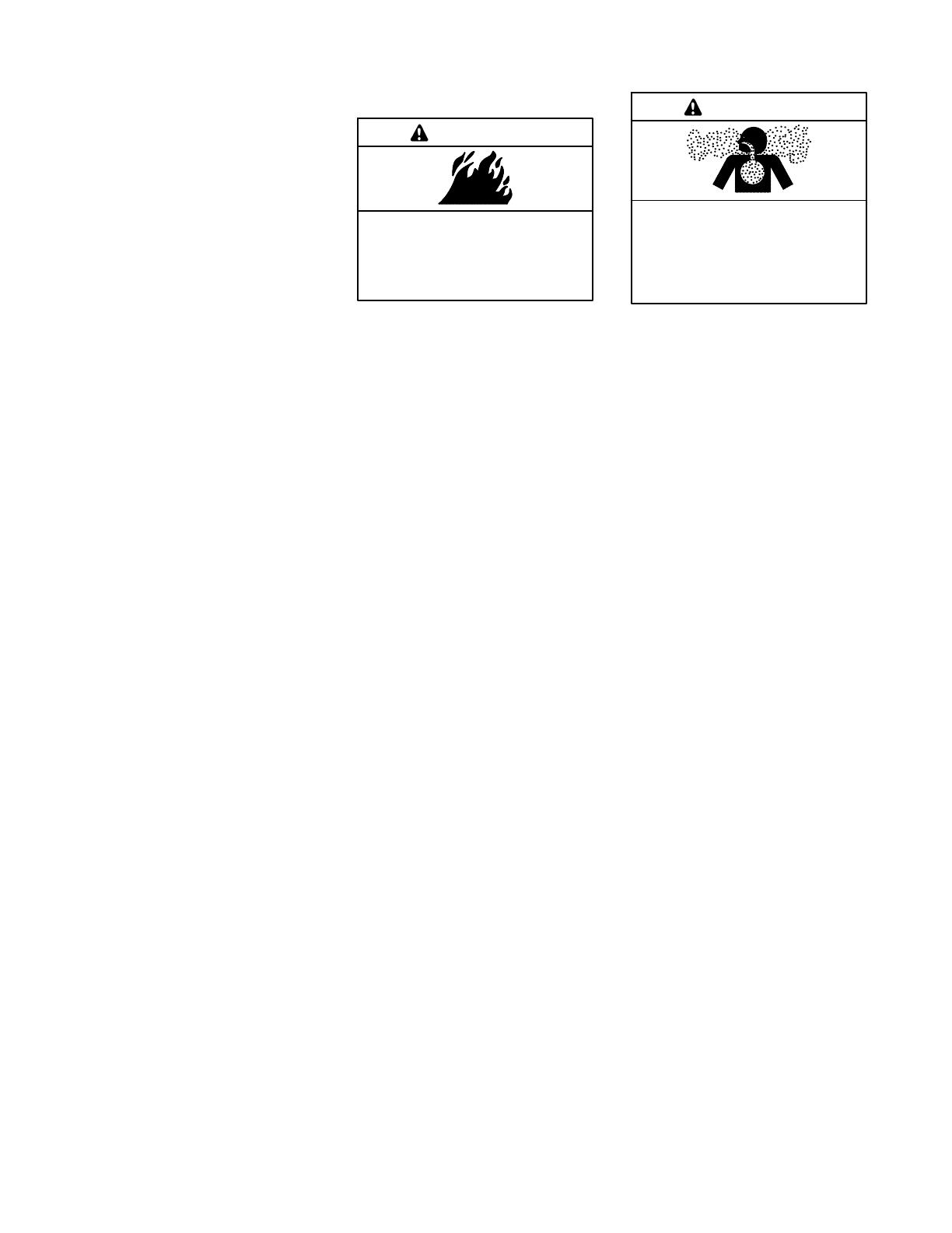
Engine Backfire/Flash
Fire
Risk of fire.
Can cause severe injury or death.
Do not smoke or permit flames or
sparks near fuels or the fuel system.
WARNING
Servicing the fuel system. A flash
fire can cause severe injury or death.
Do not smoke or permit flames or
sparks near the carburetor, fuel line,
fuel filter, fuel pump, or other potential
sources of spilled fuels or fuel vapors.
Catch fuels in an approved container
when removing the fuel line or
carburetor.
Servicing the air cleaner. A sudden
backfire can cause severe injury or
death. Do not operate the generator
set with the air cleaner removed.
Combustible materials. A fire can
cause severe injury or death.
Generator set engine fuels and fuel
vapors are flammable and explosive.
Handle these materials carefully to
minimize the risk of fire or explosion.
Equip the compartment or nearby area
with a fully charged fire extinguisher.
Select a fire extinguisher rated ABC or
BC for electrical fires or as
recommended by the local fire code or
an authorized agency. Train all
personnel on fire extinguisher
operation and fire prevention
procedures.
Exhaust System
Carbon monoxide.
Can cause severe nausea,
fainting, or death.
The exhaust system must be
leakproof and routinely inspected.
WARNING
Generator set operation. Carbon
monoxide can cause severe nausea,
fainting, or death. Carbon monoxide
is an odorless, colorless, tasteless,
nonirritating gas that can cause death if
inhaled for even a short time. Avoid
breathing exhaust fumes when working
on or near the generator set. Never
operate the generator set inside a
building unless the exhaust gas is
piped safely outside. Never operate
the generator set where exhaust gas
could accumulate and seep back inside
a potentially occupied building.
Carbon monoxide symptoms.
Carbon monoxide can cause severe
nausea, fainting, or death. Carbon
monoxide is a poisonous gas present in
exhaust gases. Carbon monoxide is an
odorless, colorless, tasteless,
nonirritating gas that can cause death if
inhaled for even a short time. Carbon
monoxide poisoning symptoms include
but are not limited to the following:
D Light-headedness, dizziness
D Physical fatigue, weakness in
joints and muscles
D Sleepiness, mental fatigue,
inability to concentrate
or speak clearly, blurred vision
D Stomachache, vomiting, nausea
If experiencing any of these symptoms
and carbon monoxide poisoning is
possible, seek fresh air immediately
and remain active. Do not sit, lie down,
or fall asleep. Alert others to the
possibility of carbon monoxide
poisoning. Seek medical attention if
the condition of affected persons does
not improve within minutes of breathing
fresh air.
9Safety Precautions and InstructionsTP-6200 7/18
Fuel System
Explosive fuel vapors.
Can cause severe injury or death.
Use extreme care when handling,
storing, and using fuels.
WARNING
The fuel system. Explosive fuel
vapors can cause severe injury or
death. Vaporized fuels are highly
explosive. Use extreme care when
handling and storing fuels. Store fuels
in a well-ventilated area away from
spark-producing equipment and out of
the reach of children. Never add fuel to
the tank while the engine is running
because spilled fuel may ignite on
contact with hot parts or from sparks.
Do not smoke or permit flames or
sparks to occur near sources of spilled
fuel or fuel vapors. Keep the fuel lines
and connections tight and in good
condition. Do not replace flexible fuel
lines with rigid lines. Use flexible
sections to avoid fuel line breakage
caused by vibration. Do not operate the
generator set in the presence of fuel
leaks, fuel accumulation, or sparks.
Repair fuel systems before resuming
generator set operation.
Explosive fuel vapors can cause
severe injury or death. Take
additional precautions when using the
following fuels:
Gasoline—Store gasoline only in
approved red containers clearly
marked GASOLINE.
Propane (LPG)—Adequate ventilation
is mandatory. Because propane is
heavier than air, install propane gas
detectors low in a room. Inspect the
detectors per the manufacturer’s
instructions.
Natural Gas—Adequate ventilation is
mandatory. Because natural gas rises,
install natural gas detectors high in a
room. Inspect the detectors per the
manufacturer’s instructions.
Fuel tanks. Explosive fuel vapors
can cause severe injury or death.
Gasoline and other volatile fuels stored
in day tanks or subbase fuel tanks can
cause an explosion. Store only diesel
fuel in tanks.
Draining the fuel system. Explosive
fuel vapors can cause severe injury
or death. Spilled fuel can cause an
explosion. Use a container to catch fuel
when draining the fuel system. Wipe up
spilled fuel after draining the system.
Gas fuel leaks. Explosive fuel
vapors can cause severe injury or
death. Fuel leakage can cause an
explosion. Check the LPG vapor or
natural gas fuel system for leakage by
using a soap and water solution with
the fuel system test pressurized to
6--8 ounces per square inch
(10--14 inches water column). Do not
use a soap solution containing either
ammonia or chlorine because both
prevent bubble formation. A successful
test depends on the ability of the
solution to bubble.
LPG liquid withdrawal fuel leaks.
Explosive fuel vapors can cause
severe injury or death. Fuel leakage
can cause an explosion. Check the
LPG liquid withdrawal fuel system for
leakage by using a soap and water
solution with the fuel system test
pressurized to at least 90 psi
(621 kPa). Do not use a soap solution
containing either ammonia or chlorine
because both prevent bubble
formation. A successful test depends
on the ability of the solution to bubble.
Hazardous Noise
Hazardous noise.
Can cause hearing loss.
Never operate the generator set
without a muffler or with a faulty
exhaust system.
CAUTION
Engine noise. Hazardous noise can
cause hearing loss. Generator sets
not equipped with sound enclosures
can produce noise levels greater than
105 dBA. Prolonged exposure to noise
levels greater than 85 dBA can cause
permanent hearing loss. Wear hearing
protection when near an operating
generator set.
10 Safety Precautions and Instructions TP-6200 7/18
Hazardous Voltage/
Moving Parts
Hazardous voltage.
Will cause severe injury or death.
Disconnect all power sources before
opening the enclosure.
DANGER
Hazardous voltage. Moving parts.
Will cause severe injury or death.
Operate the generator set only when
all guards and electrical enclosures
areinplace.
DANGER
Hazardous voltage.
Backfeed to the utility system can
cause property damage, severe
injury, or death.
If the generator set is used for
standby power, install an automatic
transfer switch to prevent inadvertent
interconnection of standby and
normal sources of supply.
WARNING
Grounding electrical equipment.
Hazardous voltage will cause severe
injury or death. Electrocution is
possible whenever electricity is
present. Ensure you comply with all
applicable codes and standards.
Electrically ground the generator set,
transfer switch, and related equipment
and electrical circuits. Turn off the main
circuit breakers of all power sources
before servicing the equipment. Never
contact electrical leads or appliances
when standing in water or on wet
ground because these conditions
increase the risk of electrocution.
High voltage test. Hazardous
voltage will cause severe injury or
death. Follow the instructions of the
test equipment manufacturer when
performing high-voltage tests on the
rotor or stator. An improper test
procedure can damage equipment or
lead to generator set failure.
Installing the battery charger.
Hazardous voltage will cause severe
injury or death. An ungrounded
battery charger may cause electrical
shock. Connect the battery charger
enclosure to the ground of a permanent
wiring system. As an alternative, install
an equipment grounding conductor
with circuit conductors and connect it to
the equipment grounding terminal or
the lead on the battery charger. Install
the battery charger as prescribed in the
equipment manual. Install the battery
charger in compliance with local codes
and ordinances.
Connecting the battery and the
battery charger. Hazardous voltage
will cause severe injury or death.
Reconnect the battery correctly,
positive to positive and negative to
negative, to avoid electrical shock and
damage to the battery charger and
battery(ies). Have a qualified
electrician install the battery(ies).
Short circuits. Hazardous
voltage/current will cause severe
injury or death. Short circuits can
cause bodily injury and/or equipment
damage. Do not contact electrical
connections with tools or jewelry while
making adjustments or repairs.
Remove all jewelry before servicing the
equipment.
Engine block heater. Hazardous
voltage will cause severe injury or
death. The engine block heater can
cause electrical shock. Remove the
engine block heater plug from the
electrical outlet before working on the
block heater electrical connections.
Electrical backfeed to the utility.
Hazardous backfeed voltage can
cause severe injury or death. Install
a transfer switch in standby power
installations to prevent the connection
of standby and other sources of power.
Electrical backfeed into a utility
electrical system can cause severe
injury or death to utility personnel
working on power lines.
Testing live electrical circuits.
Hazardous voltage or current will
cause severe injury or death. Have
trained and qualified personnel take
diagnostic measurements of live
circuits. Use adequately rated test
equipment with electrically insulated
probes and follow the instructions of the
test equipment manufacturer when
performing voltage tests. Observe the
following precautions when performing
voltage tests: (1) Remove all jewelry.
(2) Stand on a dry, approved electrically
insulated mat. (3) Do not touch the
enclosure or components inside the
enclosure. (4) Be prepared for the
system to operate automatically.
(600 volts and under)
Servicing the generator set when it
is operating. Exposed moving parts
will cause severe injury or death.
Keep hands, feet, hair, clothing, and
test leads away from the belts and
pulleys when the generator set is
running. Replace guards, screens, and
covers before operating the generator
set.
11Safety Precautions and InstructionsTP-6200 7/18
Heavy Equipment
Unbalanced weight.
Improper lifting can cause severe
injury or death and equipment
damage.
Do not use lifting eyes.
Lift the generator set using lifting bars
inserted through the lifting holes on
the skid.
WARNING
Hot Parts
Hot coolant and steam.
Can cause severe injury or death.
Before removing the pressure cap,
stop the generator set and allow it to
cool. Then loosen the pressure cap
to relieve pressure.
WARNING
Hot engine and exhaust system.
Can cause severe injury or death.
Do not work on the generator set until
it cools.
WARNING
Servicing the alternator. Hot parts
can cause severe injury or death.
Avoid touching the alternator field or
exciter armature. When shorted, the
alternator field and exciter armature
become hot enough to cause severe
burns.
Servicing the exhaust system. Hot
parts can cause severe injury or
death. Do not touch hot engine parts.
The engine and exhaust system
components become extremely hot
during operation.
Notice
NOTICE
This generator set has been
rewired from its nameplate voltage
to
246242
NOTICE
Voltage reconnection. Affix a notice
to the generator set after reconnecting
the set to a voltage different from the
voltage on the nameplate. Order
voltage reconnection decal 246242
from an authorized service
distributor/dealer.
NOTICE
Canadian installations only.For
standby service connect the output of
the generator set to a suitably rated
transfer switch in accordance with
Canadian Electrical Code, Part 1.
12 Safety Precautions and Instructions TP-6200 7/18
Notes
13IntroductionTP-6200 7/18
Introduction
This manual provides operation instructions for 20 kW
and larger generator sets equipped with the following
controller:
D Decisionr 550, Software (Code) Version 2.10 or
higher
Version 2.10 refers to the controller application
software. To determine the generator set controller
software version, go to Menu 20—Factory Setup and
scroll down to Code Version. The code version is the
controller software version.
Wiring diagram manuals are available separately. Refer
to the engine operation manual for generator set engine
scheduled maintenance information.
Information in this publication represents data available
at the time of print. Kohler Co. reserves the right to
change this publication and the products represented
without notice and without any obligation or liability
whatsoever.
Read this manual and carefully follow all procedures
and safety precautions to ensure proper equipment
operation and to avoid bodily injury. Read and follow the
Safety Precautions and Instructions section at the
beginning of this manual. Keep this manual with the
equipment for future reference.
The equipment service requirements are very important
to safe and efficient operation. Inspect the parts often
and perform required service at the prescribed intervals.
Maintenance work must be performed by appropriately
skilled and suitably trained maintenance personnel
familiar with generator set operation and service.
The disk supplied with this generator set is a backup
copy of the generator set personality program
containing data specific to the engine and alternator.
The engine and alternator data was preprogrammed in
the controller at the factory and no further use of the disk
should be necessary. Typically, your authorized
distributor stores this disk for possible future use such as
controller replacement or other circumstances requiring
a backup.
Abbreviations
This publication makes use of numerous abbreviations.
Typically, the word(s) are spelled out along with the
abbreviation in parentheses when shown for the first
time in a section. Appendix A, Abbreviations, also
includes many abbreviation definitions.
List of Related Materials
Separate literature contains communication and
software information not provided in this manual.
Figure 1 lists the available literature part numbers.
Communication and Software
Manual Description
Literature Part No.
550 Controller Spec Sheet
G6-46
Generator Set/Controller
Wiring Diagram Manual
Multiple Part Numbers
Contact your
Distributor/Dealer
550 Communications Spec Sheet
G6-50
Monitor III Converters, Connections,
and Controller Setup
TT-1405
Monitor III Software Spec Sheet G6-76
Monitor III Converter,
Modbusr/Ethernet Spec Sheet
G6-79
Monitor III Software Operation Manual TP-6347
Modbusr Communications Protocol
Operation Manual
TP-6113
Setup and Application Manual TP-6140
Service Parts Controllers TP-6780
Program Loader Software Installation TT-1285
SiteTecht Software Operation Manual
TP-6701
Remote Serial Annunciator (RSA) TT-1377
Remote Serial Annunciator (RSA II) TT-1485
Controller Service Replacement TT-1310
Figure 1 Related Literature
Modbusr is a registered trademark of Schneider Electric.
14 Service Assistance TP-6200 7/18
Service Assistance
For professional advice on generator set power
requirements and conscientious service, please contact
your nearest Kohler distributor or dealer.
D Visit the Kohler Co. website at KOHLERPower.com.
D Look at the labels and decals on your Kohler product
or review the appropriate literature or documents
included with the product.
D Call toll free in the US and Canada 1-800-544-2444.
D Outside the US and Canada, call the nearest regional
office.
Headquarters Europe, Middle East, Africa
(EMEA)
Kohler EMEA Headquarters
Netherlands B.V.
Kristallaan 1
4761 ZC Zevenbergen
The Netherlands
Phone: (31) 168 331630
Fax: (31) 168 331631
Asia Pacific
Kohler Asia Pacific Headquarters
Singapore, Republic of Singapore
Phone: (65) 6264-6422
Fax: (65) 6264-6455
China
North China Regional Office, Beijing
Phone: (86) 10 6518 7950
(86) 10 6518 7951
(86) 10 6518 7952
Fax: (86) 10 6518 7955
East China Regional Office, Shanghai
Phone: (86) 21 6288 0500
Fax: (86) 21 6288 0550
India, Bangladesh, Sri Lanka
India Regional Office
Bangalore, India
Phone: (91) 80 3366208
(91) 80 3366231
Fax: (91) 80 3315972
Japan, Korea
North Asia Regional Office
Tokyo, Japan
Phone: (813) 3440-4515
Fax: (813) 3440-2727
TP-6200 7/18 15Section 1 Specifications and Features
Section 1 Specifications and Features
1.1 Introduction
The spec sheets for each generator set provide model-
specific generator and engine information. The
controller spec sheet provides specifications for this
controller. Refer to the respective spec sheet for data
not supplied in this manual. Consult the generator set
service manual, installation manual, engine operation
manual, and engine service manual for additional
specifications.
1.2 Controller Features
The controller features include the annunciator lamps,
digital display and keypad, switches and controls, and
fuses and terminal strip. The following paragraphs
detail the features by general topics.
The controller features, accessories, and menu displays
depend upon the engine electronic control module
(ECM) setup and features. Controller features apply to
generator set models with ECM and non-ECM engines
unless otherwise noted.
Note: Press any key on the keypad to turn on the
controller lights and display. The lights and
display turn off 5 minutes after the last keypad
entry.
Note: Measurements display in metric or English. Use
Menu 7—Generator System to change the
measurement display.
See Figure 1-1 for an illustration of the controller front
panel. See Figure 1-2 for an illustration of the controller
with the keyswitch option.
1. Emergency stop switch
2. Alarm horn (see keypad for alarm silence)
3. Annunciator lamps (see keypad for lamp test)
4. Generator set master switch, run/off -reset/auto positions
5. Digital display
6. Keypad
7. Operating guide
8. Controller terminal strips (on circuit board)
TP-6083-2
124 5
7
8
3 6
Figure 1-1 550 Controller with Three-Position Selector Switch
TP-6200 7/1816 Section 1 Specifications and Features
1. Generator set master switch, run/off -reset/auto positions
(keyswitch option)
2. Emergency stop switch
3. Alarm horn (see keypad for alarm silence)
4. Annunciator lamps (see keypad for lamp test)
5. Digital display
6. Keypad
7. Operating guide
8. Controller terminal strips (on circuit board)
TP-6083-2
12 4 5
7
8
3 6
Figure 1-2 550 Controller with Keyswitch Option
1.2.1 Annunciator Lamps
Five annunciator lamps provide visual generator set
status. See Figure 1 -3.
TP-6083-2
Figure 1-3 Annunciator Lamps
System Ready. Green lamp illuminates when the
generator set master switch is in the AUTO (automatic
start) position and the system senses no faults. The unit
is ready to start.
Not in Auto (NIA). Yellow lamp illuminates when the
generator set master switch is not in the AUTO
(automatic start) position.
Programming Mode. Yellow programming lamp
indicates the user selected programming mode. See
Figure 1-4.
Programming Lamp Programming Mode Selection
Lamp Flashing Local Programming
Lamp Steady On Remote Programming
Lamp Off Programming Disabled
Figure 1-4 Programming Lamp Mode
Note: Find additional information for the programming
mode lamp function and access to the local or
remote programming modes in Section 2.9, Local
Programming Mode On, Menu 14—Programming
Mode.
TP-6200 7/18 17Section 1 Specifications and Features
System Warning. Yellow lamp identifies an existing
fault condition that does not shut down the generator
set. A continuing system warning fault condition may
cause a system shutdown. Correct all system warnings
as soon as practical.
See Section 2.4.5, System Warning Lamp, for
definitions of the items listed.
The following conditions cause a system warning:
D Engine functions:
d ECM yellow alarm
(DDC/MTU engine with MDEC/ADEC)
d High battery voltage
d High coolant temperature
d Low battery voltage
d Low coolant temperature
d Low fuel (level or pressure)*
d Low oil pressure
d Speed sensor fault
d Starting aid (system status)
d Weak battery
D General functions:
d Auxiliary—Analog up to 7 user-selectable inputs
each with a high and low programmable warning
level
d Auxiliary—Digital up to 21 user-selectable
warnings
d Battery charger communication error
d Battery charger fault*
Note: Optional input sensors not required with
charger GM87448.
d Battery charger value mismatch error
d Emergency power system (EPS) supplying load
d Engine cooldown delay
d Engine start delay
d Load shed kW overload
d Load shed underfrequency
d Master switch not in AUTO (automatic start)
position
d NFPA 110 fault (National Fire Protection
Association)
d System ready (system status)
D Alternator functions:
d AC sensing loss
d Ground fault*
d Overcurrent
* Requires optional input sensors
Note: See Figure 2-8 in User Inputs for factory-
reserved analog and digital inputs that are not
user-selectable.
System Shutdown. Red lamp indicates that the
generator set has shut down because of a fault
condition. The unit will not start without resetting the
controller, see Section 2.4.7, Controller Reset
Procedure.
See Section 2.4.6, System Shutdown Lamp, for
definitions of the items listed.
The following conditions cause a system shutdown:
D Engine functions:
d Air damper closed (status), if equipped
d Coolant temperature signal loss
d ECM red alarm
(DDC/MTU engine with MDEC/ADEC)
d Engine stalled (ECM only)
d High coolant temperature
d High oil temperature
d Low coolant level
d Low oil pressure
d Oil pressure signal loss
d Overcrank
d Overspeed
D General functions:
d Auxiliary—Analog up to 7 user-selectable inputs
each with a high and low programmable
shutdown level
d Auxiliary—Digital up to 21 user-selectable
shutdowns
d ECM communications loss (ECM models only)
d Emergency stop
d Internal fault
d Master switch in OFF/RESET position
d Master switch error
d Master switch open
d NFPA 110 fault
D Alternator functions:
d AC output overvoltage
d AC output undervoltage
d Alternator protection against overload and short
circuits
d Field overvoltage
(M4, M5, M7, or M10 a lternator only)
d Locked rotor (failed to crank)
d Overfrequency
d Underfrequency
Note: See Figure 2-8 in User Inputs for factory-
reserved analog and digital inputs which are
not user-selectable.
TP-6200 7/1818 Section 1 Specifications and Features
1.2.2 Digital Display and Keypad
Figure 1-5 illustrates the digital display and keypad.
Note: Press any key on the keypad to turn on the
controller lights and display. The lights and
display turn off 5 minutes after the last keypad
entry.
The 2-line vacuum fluorescent display provides
generator set and engine condition information.
The 16-button keypad gives the user information access
and local programming capability.
Keypad Functions
Alarm (Horn) Off key silences the alarm horn at the
operator’s discretion. Place the generator set master
switch in the AUTO position before silencing the alarm
horn. See Section 2.4.7, Controller Reset Procedure,
and Section 1.2.3, Switches and Controls.
AM/PM key provides time of day data entries when
programming.
Enter ï‚¿ key provides confirmation entry when selecting
menu or programming.
Lamp Test key tests the controller indicator lamps,
horn, and digital display. See Section 1.2.3, Switches
and Controls.
Menu down  key provides navigation within menus
when necessary.
Menu right ï‚® key provides navigation within menus
when necessary.
Numeric 0--9 keys provide numeric data entries when
selecting menus or programming.
Reset Menu key exits a menu, clears incorrect entries,
and cancels the auto-scroll feature.
Stop Prog (Program) Run key allowstheusertostop
any previously programmed generator set run
sequence. See Section 1.2.3, Switches and Controls.
Yes/No keys provides data answer entries when
programming.
TP-5829-2
Figure 1-5 Digital Display and Keypad
Alternator Output Displays (Menu 1)
AC Amps displays the a lternator output current. The
display shows each line of 3-phase models.
AC Volts displays the alternator output voltages. The
display shows all line-to-neutral and line-to-line voltage
combinations.
Alternator Duty Level displays the actual load kW
divided by the nameplate kW rating as a percentage.
Frequency displays the frequency (Hz) of alternator
output voltage.
Hourmeter displays the generator set operating hours
loaded and unloaded for reference in scheduling
maintenance.
KVA displays the total and individual L1, L2, and L3 kVA.
KVAR displays the total and individual L1, L2, and L3
kVAR.
Power Factor displays the kW/kVA and the individual
line power factor values.
Watts displays the total and individual L1, L2, and L3
kilowatts.
TP-6200 7/18 19Section 1 Specifications and Features
Engine Displays (Menu 2)
Some engine displays are available with selected
generator set engines using engine ECMs only. The
controller display shows N/A (not available) for items
that are unavailable. See the controller spec sheet for
applicable generator set models.
Ambient Temperature displays the generator set area
ambient temperature.
Charge Air Pressure displays the engine turbocharger
boost air pressure.
Charge Air Temperature displays the engine
turbocharger boost air temperature.
Coolant Level displays the engine coolant level.
Coolant Pressure displays the engine coolant
pressure.
Coolant Temperature displays the engine coolant
temperature.
Crankcase Pressure displays the engine crankcase
pressure.
DC Volts displays the voltage of starting battery(ies).
Fuel Pressure displays the fuel supply pressure.
Fuel Rate displays the calculated fuel consumption rate
based on fuel injector outputs.
Fuel Temperature displays the fuel supply
temperature.
Oil Level displays the engine oil level as a percent of full
capacity.
Oil Pressure displays the engine oil pressure.
Oil Temperature displays the engine oil temperature.
RPM (Tachometer) displays the engine speed.
Used Last Run displays the accumulated amount of
fuel used since last reset by the engine DDEC reader.
Operational Record Displays (Menus 4 and 5)
The operational record displays events since last reset.
See Section 2.9.4, Menu 4—Operational Records, for
resetting procedure.
Engine Start Countdown displays the time remaining
before the next generator set startup.
Event History displays up to 100 stored system events
including status, warnings, and shutdowns.
Last Start Date displays the date when the generator
set last operated.
Number of Starts displays the total number of
generator set startup events.
Number of Starts (Since) Last Maintenance displays
the total number of generator set startup events since
the last maintenance date.
Operating Days (Since) Last Maintenance displays
the total number of days of operation since the last
maintenance date. A counted day of operation can be
1--24 hours.
Run Time displays the total loaded hours, total
unloaded hours, and total kW hours.
Run Time Since Maintenance displays the total loaded
hours, total unloaded hours, and total kW hours.
Time Delay Displays (Menu 8)
The time delays are user adjustable. See Section 2.9.8,
Menu 8—TIme Delays, for time delay adjustments. See
Section 1.3.1, Status Event and Fault Specifications, for
range and default settings.
Crank On/Crank Pause displays the time allocated for
generator set crank on and crank pause in
minutes:seconds.
Engine Cooldown displays the time delay for engine
cooldown while the master switch is in the AUTO or RUN
positions and not in the idle mode.
Engine Start displays the time delay before the
generator set starts while the master switch is in AUTO
or RUN positions.
Overcrank Shutdown (Number of) Crank Cycles
displays the number of unsuccessful crank cycles
(crank on/crank pause) before the generator set shuts
down on an overcrank fault.
Overvoltage displays the time delay before the
generator set shuts down because of an overvoltage
condition.
Starting Aid displays the engine starting aid activation
time.
Undervoltage displays the time delay before the
generator set shuts down because of an undervoltage
condition.
TP-6200 7/1820 Section 1 Specifications and Features
1.2.3 Switches and Cont rols
See Figure 1-6 and Figure 1-8 for switches and
controls.
TP-6083-2
1. Emergency stop switch
2. Alarm horn
3. Generator set master switch
123
Figure 1-6 Switches and Alarm Horn
Note: Find additional switches and controls in
Section 2.6.1, Keypad Operation.
Alarm Horn. The alarm horn alerts the operator or other
attendants that a shutdown or warning condition exists.
See Section 1.3, Controller Logic Specifications, for
conditions. Place the generator set master switch in the
AUTO position before silencing the alarm horn. The
alarm horn cannot be silenced unless the generator set
master switch is in the AUTO position. See
Section 2.4.7, Controller Reset Procedure.
Alarm (Horn) Off. The keypad switch silences the
alarm horn at the operator’s discretion. Place the
generator set master switch in the AUTO position before
silencing the alarm horn. Restore alarm horn switches
at all locations including those on remote annunciator
and audiovisual alarm kits to the normal position after
correcting the fault shutdown to avoid reactivating the
alarm horn. See Section 2.4.7, Controller Reset
Procedure.
AM/PM. This keypad switch provides time of day data
entries when programming.
Emergency Stop. The operator-activated pushbutton
immediately shuts down the generator set in emergency
situations. Reset the emergency stop switch after
shutdown by pulling the switch knob outward. Use the
emergency stop switch for emergency shutdowns only.
Use the generator set master switch for normal
shutdowns.
Generator Set Master Switch (Run/Off-Reset/Auto).
This switch resets the controller fault lamps and
start/stops the generator set. Refer to Section 2.4.1,
Starting, Section 2.4.2, Stopping, and Section 2.4.3,
Emergency Stop Switch Reset Procedure.
The generator set master switch with the keyswitch
option (Figure 1-7) is available to meet appropriate local
code requirements. The key is removable in the AUTO
position only.
TP-6083-2
Figure 1-7 Generator Set Master Switch with
Keyswitch Option
Lamp Test. The keypad switch tests the controller
indicator lamps, horn, and digital display. Press the
reset menu key before pressing the lamp test key.
Stop Prog (Program) Run. Keypad switch allows the
user to stop any previously programmed generator set
run sequence.
1
2
TP-5829-2
1. Lamp test
2. Alarm horn silence
3. Stop program run
3
Figure 1-8 Keypad Switches
  • Page 1 1
  • Page 2 2
  • Page 3 3
  • Page 4 4
  • Page 5 5
  • Page 6 6
  • Page 7 7
  • Page 8 8
  • Page 9 9
  • Page 10 10
  • Page 11 11
  • Page 12 12
  • Page 13 13
  • Page 14 14
  • Page 15 15
  • Page 16 16
  • Page 17 17
  • Page 18 18
  • Page 19 19
  • Page 20 20
  • Page 21 21
  • Page 22 22
  • Page 23 23
  • Page 24 24
  • Page 25 25
  • Page 26 26
  • Page 27 27
  • Page 28 28
  • Page 29 29
  • Page 30 30
  • Page 31 31
  • Page 32 32
  • Page 33 33
  • Page 34 34
  • Page 35 35
  • Page 36 36
  • Page 37 37
  • Page 38 38
  • Page 39 39
  • Page 40 40
  • Page 41 41
  • Page 42 42
  • Page 43 43
  • Page 44 44
  • Page 45 45
  • Page 46 46
  • Page 47 47
  • Page 48 48
  • Page 49 49
  • Page 50 50
  • Page 51 51
  • Page 52 52
  • Page 53 53
  • Page 54 54
  • Page 55 55
  • Page 56 56
  • Page 57 57
  • Page 58 58
  • Page 59 59
  • Page 60 60
  • Page 61 61
  • Page 62 62
  • Page 63 63
  • Page 64 64
  • Page 65 65
  • Page 66 66
  • Page 67 67
  • Page 68 68
  • Page 69 69
  • Page 70 70
  • Page 71 71
  • Page 72 72
  • Page 73 73
  • Page 74 74
  • Page 75 75
  • Page 76 76
  • Page 77 77
  • Page 78 78
  • Page 79 79
  • Page 80 80
  • Page 81 81
  • Page 82 82
  • Page 83 83
  • Page 84 84
  • Page 85 85
  • Page 86 86
  • Page 87 87
  • Page 88 88
  • Page 89 89
  • Page 90 90
  • Page 91 91
  • Page 92 92
  • Page 93 93
  • Page 94 94
  • Page 95 95
  • Page 96 96
  • Page 97 97
  • Page 98 98
  • Page 99 99
  • Page 100 100
  • Page 101 101
  • Page 102 102
  • Page 103 103
  • Page 104 104
  • Page 105 105
  • Page 106 106
  • Page 107 107
  • Page 108 108
  • Page 109 109
  • Page 110 110
  • Page 111 111
  • Page 112 112
  • Page 113 113
  • Page 114 114
  • Page 115 115
  • Page 116 116
  • Page 117 117
  • Page 118 118
  • Page 119 119
  • Page 120 120
  • Page 121 121
  • Page 122 122
  • Page 123 123
  • Page 124 124
  • Page 125 125
  • Page 126 126
  • Page 127 127
  • Page 128 128
  • Page 129 129
  • Page 130 130
  • Page 131 131
  • Page 132 132
  • Page 133 133
  • Page 134 134
  • Page 135 135
  • Page 136 136
  • Page 137 137
  • Page 138 138
  • Page 139 139
  • Page 140 140
  • Page 141 141
  • Page 142 142
  • Page 143 143
  • Page 144 144
  • Page 145 145
  • Page 146 146
  • Page 147 147
  • Page 148 148
  • Page 149 149
  • Page 150 150
  • Page 151 151
  • Page 152 152
  • Page 153 153
  • Page 154 154
  • Page 155 155
  • Page 156 156
  • Page 157 157
  • Page 158 158
  • Page 159 159
  • Page 160 160
  • Page 161 161
  • Page 162 162
  • Page 163 163
  • Page 164 164
  • Page 165 165
  • Page 166 166
  • Page 167 167
  • Page 168 168
  • Page 169 169
  • Page 170 170
  • Page 171 171
  • Page 172 172
  • Page 173 173
  • Page 174 174
  • Page 175 175
  • Page 176 176
  • Page 177 177
  • Page 178 178
  • Page 179 179
  • Page 180 180
  • Page 181 181
  • Page 182 182
  • Page 183 183
  • Page 184 184
  • Page 185 185
  • Page 186 186
  • Page 187 187
  • Page 188 188
  • Page 189 189
  • Page 190 190
  • Page 191 191
  • Page 192 192
  • Page 193 193
  • Page 194 194
  • Page 195 195
  • Page 196 196
  • Page 197 197
  • Page 198 198
  • Page 199 199
  • Page 200 200
  • Page 201 201
  • Page 202 202
  • Page 203 203
  • Page 204 204
  • Page 205 205
  • Page 206 206
  • Page 207 207
  • Page 208 208
  • Page 209 209
  • Page 210 210
  • Page 211 211
  • Page 212 212
  • Page 213 213
  • Page 214 214
  • Page 215 215
  • Page 216 216
  • Page 217 217
  • Page 218 218
  • Page 219 219
  • Page 220 220
  • Page 221 221
  • Page 222 222
  • Page 223 223
  • Page 224 224
  • Page 225 225
  • Page 226 226
  • Page 227 227
  • Page 228 228
  • Page 229 229
  • Page 230 230
  • Page 231 231
  • Page 232 232
  • Page 233 233
  • Page 234 234
  • Page 235 235
  • Page 236 236

Kohler 100REZGD Operating instructions

Category
Power generators
Type
Operating instructions

Ask a question and I''ll find the answer in the document

Finding information in a document is now easier with AI