
SERVICE MANUAL
DVD RECEIVER
Ver. 1.1 2007.03
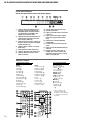
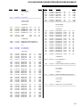
SPECIFICATIONS
– Continued on next page –
US Model
HCD-HDX265/HDX266/HDX267W/HDX465
Canadian Model
HCD-HDX466/HDX665
E Model
Australian Model
HCD-HDX265
HCD-HDX265/HDX266/HDX267W/
HDX465/HDX466/HDX665
9-887-551-02
2007C05-1
© 2007.03
Sony Corporation
Home Audio Division
Published by Sony Techno Create Corporation
•HCD-HDX265 is the amplifier, DVD
system, tuner and video section in
DAV-HDX265.
•HCD-HDX266 is the amplifier, DVD
system, tuner and video section in
DAV-HDX266.
•HCD-HDX267W is the amplifier, DVD
system, tuner and video section in
DAV-HDX267W.
•HCD-HDX465 is the amplifier, DVD
system, tuner and video section in
DAV-HDX465.
•HCD-HDX466 is the amplifier, DVD
system, tuner and video section in
DAV-HDX466.
•HCD-HDX665 is the amplifier, DVD
system, tuner and video section in
DAV-HDX665.
Photo: HCD-HDX265
Model Name Using Similar Mechanism HCD-DX155
DVD Mechanism Type CDM81C-DVBU101
Optical Pick-up Block Name KHM-310CAB or
KHM-313CAB
This product incorporates copyright protection
technology that is protected by U.S. patents and
other intellectual property rights. Use of this
copyright protection technology must be
authorized by Macrovision, and is intended for
home and other limited viewing uses only unless
otherwise authorized by Macrovision. Reverse
engineering or disassembly is prohibited.
This system incorporates with Dolby* Digital
and Dolby Pro Logic (II) adaptive matrix
surround decoder and the DTS** Digital
Surround System.
*Manufactured under license from Dolby
Laboratories.
“Dolby”, “Pro Logic”, and the double-D symbol are
trademarks of Dolby Laboratories.
**Manufactured under license from DTS, Inc.
“DTS” and “DTS Digital Surround” are registered
trademarks of DTS, Inc.
AUDIO POWER SPECIFICATIONS
for the US model
POWER OUTPUT AND TOTAL HARMONIC
DISTORTION: With 3 ohms loads, both
channels driven, from 120
- 20,000 Hz; rated 84 watts
per channel minimum
RMS power, with no more
than 0.7 % total harmonic
distortion from 250 milli
watts to rated output.
Amplifier section
EXCEPT HCD-HDX266
US models:
Surround mode (reference) RMS output power
FL/FR/C/SL/SR*: 143 watts
(per channel at 3 ohms, 1
kHz, 10 % THD)
Subwoofer*: 285 watts (at
1.5 ohms, 80 Hz, 10 %
THD)
Other models:
Stereo mode (rated) 108 W + 108 W (at 3 ohms,
1 kHz, 1 % THD)
Surround mode (reference) RMS output power
FL/FR/C/SL/SR*: 143 watts
(per channel at 3 ohms, 1
kHz, 10 % THD)
Subwoofer*: 285 watts (at
1.5 ohms, 80 Hz, 10 %
THD)
HCD-HDX266
Surround mode (reference) RMS output power
FL/FR/C/SL/SR*: 142 watts
(per channel at 3 ohms, 1
kHz, 10 % THD)
Subwoofer*: 140 watts (at
3 ohms, 80 Hz, 10 % THD)
*Depending on the sound field settings and the source,
there may be no sound output.
Inputs (Analog)
TV/VIDEO (AUDIO IN) Sensitivity: 450/250 mV
AUDIO IN Sensitivity: 250/125 mV
Outputs (Analog)
Phones Accepts low-and high-
impedance headphones.

2
HCD-HDX265/HDX266/HDX267W/HDX465/HDX466/HDX665
ATTENTION AU COMPOSANT AYANT RAPPORT
À LA SÉCURITÉ!
LES COMPOSANTS IDENTIFIÉS PAR UNE MARQUE 0 SUR
LES DIAGRAMMES SCHÉMATIQUES ET LA LISTE DES
PIÈCES SONT CRITIQUES POUR LA SÉCURITÉ DE
FONCTIONNEMENT. NE REMPLACER CES COM- POSANTS
QUE PAR DES PIÈCES SONY DONT LES NUMÉROS SONT
DONNÉS DANS CE MANUEL OU DANS LES SUPPLÉMENTS
PUBLIÉS PAR SONY.
SAFETY-RELATED COMPONENT WARNING!!
COMPONENTS IDENTIFIED BY MARK 0 OR DOTTED LINE
WITH MARK 0 ON THE SCHEMATIC DIAGRAMS AND IN
THE PARTS LIST ARE CRITICAL TO SAFE OPERATION.
REPLACE THESE COMPONENTS WITH SONY PARTS WHOSE
PART NUMBERS APPEAR AS SHOWN IN THIS MANUAL OR
IN SUPPLEMENTS PUBLISHED BY SONY.
CAUTION
Use of controls or adjustments or performance of procedures
other than those specified herein may result in hazardous radiation
exposure.
DVD system
Laser
(CD:λ = 790 nm)
Emission duration:
continuous
Signal format system
North American models: NTSC
Other models: PAL/NTSC
Tuner section
System PLL quartz-locked digital
synthesizer
FM tuner section
Tuning range
North American models: 87.5-108.0 MHz (100 kHz
step)
Other models: 87.5-108.0 MHz (50 kHz
step)
Antenna (aerial) FM wire antenna (aerial)
Antenna (aerial) terminals 75 ohms, unbalanced
Intermediate frequency 10.7 MHz
AM tuner section
Tuning range
North Americanmodel: 530 − 1,710kHz (with the
interval set at 10 kHz)
531 − 1,710kHz (with the
interval set at 9 kHz)
Australian model: 531 − 1,710 kHz (with the
interval set at 9 kHz)
530 − 1,710 kHz (with the
interval set at 10 kHz)
Other models: 531 − 1,602 kHz (with the
interval set at 9 kHz)
530 − 1,610 kHz (with the
interval set at 10 kHz)
Antenna (aerial) AM loop antenna (aerial)
Intermediate frequency 450 kHz
Video section
Outputs VIDEO: 1 Vp-p 75 ohms
S VIDEO:
Y: 1 Vp-p 75 ohms
C: 0.286 Vp-p 75 ohms
COMPONENT:
Y: 1 Vp-p 75 ohms
P
B
/C
B
, P
R
/C
R
: 0.7 Vp-p
75 ohms
HDMI OUT: Type A (19
pin)
Semiconductor laser
(DVD:λ = 650 nm)
General
Power requirements
North American models: 120 V AC, 60 Hz
Other models: 220 - 240 V AC, 50/60 Hz
Power output (DIGITAL MEDIA PORT)
DC OUT: 5 V, 700 mA
Power consumption
EXCEPT HCD-HDX266: On: 175 W
Standby: 0.3 W (at the
Power Saving mode)
HCD-HDX266: On: 150 W
Standby: 0.3 W (at the
Power Saving mode)
Dimensions (approx.)
EXCEPT HCD-HDX267W:
430 × 86 × 415 mm (17 ×
3
1
/2 × 16
3
/8 inches) (w/h/d)
incl. projecting parts
HCD-HDX267W: 430 × 86 × 435 mm (17 ×
3
1
/2 × 17
1
/4 inches) (w/h/d)
incl. projecting parts
Mass (approx.)
EXCEPT HCD-HDX267W:
5.2 kg (11 lb 8 oz)
HCD-HDX267W: 5.4 kg (11 lb 15 oz)
Design and specifications are subject to change
without notice.
Notes on chip component replacement
•Never reuse a disconnected chip component.
•Notice that the minus side of a tantalum capacitor may be
damaged by heat.

3
HCD-HDX265/HDX266/HDX267W/HDX465/HDX466/HDX665
SAFETY CHECK-OUT
After correcting the original service problem, perform the following
safety check before releasing the set to the customer:
Check the antenna terminals, metal trim, “metallized” knobs, screws,
and all other exposed metal parts for AC leakage.
Check leakage as described below.
LEAKAGE TEST
The AC leakage from any exposed metal part to earth ground and
from all exposed metal parts to any exposed metal part having a
return to chassis, must not exceed 0.5 mA (500 microamperes.).
Leakage current can be measured by any one of three methods.
1. A commercial leakage tester, such as the Simpson 229 or RCA
WT-540A. Follow the manufacturers’ instructions to use these
instruments.
2. A battery-operated AC milliammeter. The Data Precision 245
digital multimeter is suitable for this job.
3. Measuring the voltage drop across a resistor by means of a
VOM or battery-operated AC voltmeter. The “limit” indication
is 0.75 V, so analog meters must have an accurate low-voltage
scale. The Simpson 250 and Sanwa SH-63Trd are examples
of a passive VOM that is suitable. Nearly all battery operated
digital multimeters that have a 2 V AC range are suitable. (See
Fig. A)
Fig. A. Using an AC voltmeter to check AC leakage.
1.5 k
Ω
0.15
µ
FAC
voltmete
r
(0.75 V)
To Exposed Metal
Parts on Set
Earth Ground
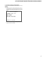
SELF DIAGNOSIS FUNCTION
When the self-diagnosis function is activated to
prevent the system from malfunctioning, a 5-
character service number (e.g., C 13 50) with a
combination of a letter and 4 digits appears on
the TV screen or front panel display. In this case,
check the following table.
When displaying the version
number on the TV screen
When you turn on the system, the version
number [VER.X.XX] (X is a number) may
appear on the TV screen. Although this is not a
malfunction and for Sony service use only,
normal system operation will not be possible.
Turn off the system, and then turn on the system
again to operate.
(When letters/numbers appear in the
display)
First 3
characters of
the service
number
Cause and/or corrective action
C 13 The disc is dirty.
,Clean the disc with a soft cloth.
C 31 The disc is not inserted correctly.
,Restart the system, then re-insert
the disc correctly.
E XX
(xx is a number) To prevent a malfunction, the
system has performed the self-
diagnosis function.
,Contact your nearest Sony
dealer or local authorized Sony
service facility and give the 5-
character service number.
Example: E 61 10
C:13:50
VER.X.XX

4
HCD-HDX265/HDX266/HDX267W/HDX465/HDX466/HDX665
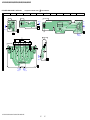
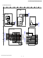
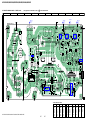
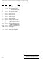
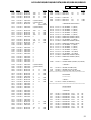
6-29. Printed Wiring Board – IO Board –................................. 58
6-30. Printed Wiring Board – FL Board – ................................ 59
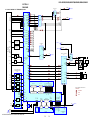
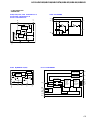
6-31. Schematic Diagram – FL Board (1/2) – .......................... 60
6-32. Schematic Diagram – FL Board (2/2) – .......................... 61
6-33. Printed Wiring Boards – PANEL Section –..................... 62
6-34. Schematic Diagram – PANEL Section – ......................... 63
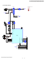
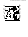
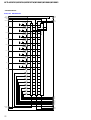
6-35. Schematic Diagram – POWER Board (1/2) – ................. 64
6-36. Schematic Diagram – POWER Board (2/2) – ................. 65
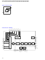
6-37. Printed Wiring Board – POWER Board – ....................... 66
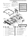
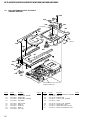
7. EXPLODED VIEWS
7-1. Case Section .................................................................... 87
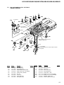
7-2. Front Panel Section ......................................................... 88
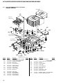
7-3. Main Section.................................................................... 89
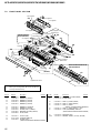
7-4. DVD Mechanism Deck Section-1
(CDM81C-DVBU101) .................................................... 90
7-5. DVD Mechanism Deck Section-2
(CDM81C-DVBU101) .................................................... 91
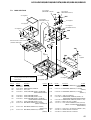
7-6. DVD Mechanism Deck Section-3
(CDM81C-DVBU101) .................................................... 92
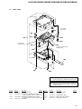
7-7. Base Unit ......................................................................... 93
8. ELECTRICAL PARTS LIST................................ 94
TABLE OF CONTENTS
1. SERVICING NOTES ............................................... 5
2. GENERAL ................................................................... 9
3. DISASSEMBLY
3-1. Disassembly Flow ........................................................... 11
3-2. Case ................................................................................. 12
3-3. DIAT CON Board............................................................ 12
3-4. IO Board .......................................................................... 13
3-5. Front Panel Block ............................................................ 13
3-6. POWER Board ................................................................ 14
3-7. Back Panel Block ............................................................ 14
3-8. DMPORT Board .............................................................. 15
3-9. MAIN Board.................................................................... 15
3-10. Cover (MD) ..................................................................... 16
3-11. DVD Mechanism deck (CDM81C-DVBU101) .............. 16
3-12. Tray (Main) Assy............................................................. 17
3-13. MOTOR Board ................................................................ 17
3-14. Base Unit (DVBU101) .................................................... 18
3-15. Optical Pick-Up Block (KHM-310CAB/313CAB) ........ 18
3-16. Gear (Sub Tray 1)/Gear (Sub Tray 2) .............................. 19
3-17. Lever Assy ....................................................................... 19
3-18. Stocker Section ................................................................ 20
3-19. Cam (Stocker).................................................................. 20
3-20. Gear (Stocker 3) .............................................................. 21
3-21. Rotary Encoder (MD)...................................................... 21
3-22. Gear (BU1) ...................................................................... 22
4. TEST MODE.............................................................. 23
5. ELECTRICAL ADJUSTMENTS ......................... 28
6. DIAGRAMS
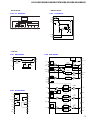
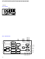
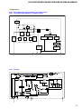
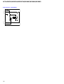
6-1. Block Diagram – RF SERVO/VIDEO Section – ............ 29
6-2. Block Diagram
– CHANGER/HDMI/DMPORT Section – ..................... 30
6-3. Block Diagram – AUDIO Section – ................................ 31
6-4. Block Diagram – AMP Section – .................................... 32
6-5. Block Diagram
– PANEL/POWER SUPPLY Section – ........................... 33
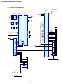
6-6. Schematic Diagram – MAIN Board (1/13) – .................. 35
6-7. Schematic Diagram – MAIN Board (2/13) – .................. 36
6-8. Schematic Diagram – MAIN Board (3/13) – .................. 37
6-9. Schematic Diagram – MAIN Board (4/13) – .................. 38
6-10. Schematic Diagram – MAIN Board (5/13) – .................. 39
6-11. Schematic Diagram – MAIN Board (6/13) – .................. 40
6-12. Schematic Diagram – MAIN Board (7/13) – .................. 41
6-13. Schematic Diagram – MAIN Board (8/13) – .................. 42
6-14. Schematic Diagram – MAIN Board (9/13) – .................. 43
6-15. Schematic Diagram – MAIN Board (10/13) – ................ 44
6-16. Schematic Diagram – MAIN Board (11/13) – ................ 45
6-17. Schematic Diagram – MAIN Board (12/13) – ................ 46
6-18. Schematic Diagram – MAIN Board (13/13) – ................ 47
6-19. Printed Wiring Board
– MAIN Board (Component Side) – ............................... 48
6-20. Printed Wiring Board
– MAIN Board (Conductor Side) – ................................. 49
6-21. Printed Wiring Board – SIRIPARA Board – ................... 50
6-22. Schematic Diagram – SIRIPARA Board –...................... 51
6-23. Printed Wiring Boards – CHANGER Section –.............. 52
6-24. Schematic Diagram – CHANGER Section – .................. 53
6-25. Printed Wiring Board – DMPORT Board – .................... 54
6-26. Schematic Diagram – DMPORT Board – ....................... 55
6-27. Schematic Diagram – IO Board (1/2) –........................... 56
6-28. Schematic Diagram – IO Board (2/2) –........................... 57

5
HCD-HDX265/HDX266/HDX267W/HDX465/HDX466/HDX665
SECTION 1
SERVICING NOTES
NOTES ON HANDLING THE OPTICAL PICK-UP
BLOCK OR BASE UNIT
The laser diode in the optical pick-up block may suffer electrostatic
break-down because of the potential difference generated by the
charged electrostatic load, etc. on clothing and the human body.
During repair, pay attention to electrostatic break-down and also
use the procedure in the printed matter which is included in the
repair parts.
The flexible board is easily damaged and should be handled with
care.
NOTES ON LASER DIODE EMISSION CHECK
The laser beam on this model is concentrated so as to be focused on
the disc reflective surface by the objective lens in the optical pick-
up block. Therefore, when checking the laser diode emission,
observe from more than 30 cm away from the objective lens.
UNLEADED SOLDER
Boards requiring use of unleaded solder are printed with the lead-
free mark (LF) indicating the solder contains no lead.
(Caution: Some printed circuit boards may not come printed with
the lead free mark due to their particular size)
: LEAD FREE MARK
Unleaded solder has the following characteristics.
•Unleaded solder melts at a temperature about 40 °C higher
than ordinary solder.
Ordinary soldering irons can be used but the iron tip has to be
applied to the solder joint for a slightly longer time.
Soldering irons using a temperature regulator should be set to
about 350 °C.
Caution: The printed pattern (copper foil) may peel away if
the heated tip is applied for too long, so be careful!
•Strong viscosity
Unleaded solder is more viscou-s (sticky, less prone to flow)
than ordinary solder so use caution not to let solder bridges
occur such as on IC pins, etc.
•Usable with ordinary solder
It is best to use only unleaded solder but unleaded solder may
also be added to ordinary solder.
RELEASING THE TRAY LOCK
The disc tray lock function for the antitheft of an demonstration
disc in the store is equipped.
Releasing Procedure :
1. Press the I/1 button to turn on the system.
2. Press the FUNCTION button repeatedly to select “DVD”.
3. While pressing the xbutton, press the A button until
“UNLOCKED” displayed on the fluorescent indicator tube
(around 5 seconds).
Note: When “LOCKED” is displayed, the tray lock is not released by turning
power on/off with the I/1button.
RELEASING THE DEMO PLAY LOCK
Releasing Procedure :
1. Press the I/1 button to turn on the system.
2. Press the FUNCTION button repeatedly to select “DVD”.
3. While pressing the xbutton, press the Hbutton until
“DEMO OFF” displayed on the fluorescent indicator tube
(around 5 seconds).
Note: When “DEMO PLAY” is displayed, the set is not possible to turn off
the system.
NOTE OF REPLACING THE EEPROM (IC1103) ON
THE MAIN BOARD
EEPROM (IC1103) on the MAIN board cannot exchange with
single. When EEPROM (IC1103) on the MAIN board is damaged,
exchange the entire mounted board.
MODEL IDENTIFICATION
MODEL PART No.
HDX465 2-892-557-2[]
HDX265: US model 2-892-557-3[]
HDX265: Australian model 2-892-557-4[]
HDX665 2-892-557-5[]
HDX466 2-892-557-6[]
HDX266 2-892-557-8[]
HDX267W 2-892-557-9[]
HDX265: E model 3-100-747-1[]
FRONT R
CENTER WOOFER
FRONT L SUR R SUR L
MONITOR OUT
TV/VIDEO ANTENNA
SPEAKER
DIR-TC1
SPEAKER
COMPONENT VIDEO OUT
COAXIAL
AM
FM
75
RLAUD IO IN
YP
B
/C
B
P
R
/C
VIDEO
(DVD ONLY)
S VIDEO
(DVD ONLY)
(DVD O
OUT
DMPORT
PART No.

6
HCD-HDX265/HDX266/HDX267W/HDX465/HDX466/HDX665
•The instructions in this manual describe the
controls on the remote. You can also use the
controls on the unit if they have the same or
similar names as those on the remote.
•The instructions in this manual are for HCD-
HDX265, HCD-HDX266, HCD-HDX267W,
HCD-HDX465, HCD-HDX466 and HCD-
HDX665. HCD-HDX265 is the model used
for illustration purposes. Any difference in
operation is clearly indicated in the text, for
•The Control Menu items may vary depending
on the area.
•“DVD” may be used as a general term for
DVD VIDEOs, DVD+RWs/DVD+Rs, and
DVD-RWs/DVD-Rs.
•Measurements are expressed in feet (ft) for
North American models.
•The following symbols are used in this
manual.
1)
MP3 (MPEG1 Audio Layer 3) is a standard format
defined by ISO/MPEG which compresses audio data.
2)
Except for United Kingdom and North American
models.
3)
DivX
®
is a video file compression technology,
developed by DivX, Inc.
4)
DivX, DivX Certified, and associated logos are
trademarks of DivX, Inc. and are used under license.
About This Manual
Symbol Meaning
Functions available for DVD
VIDEOs, DVD-Rs/DVD-RWs in
video mode, and DVD+Rs/
DVD+RWs
Functions available for DVD-Rs/
DVD-RWs in VR (Video
Recording) mode
Functions available for VIDEO
CDs (including Super VCDs or CD-
Rs/CD-RWs in video CD format or
Super VCD format)
Functions available for music CDs
or CD-Rs/CD-RWs in music CD
format
Functions available for DATA CDs
(CD-ROMs/CD-Rs/CD-RWs)
containing MP31) audio tracks,
JPEG image files, and DivX2)3)4)
video files
Functions available for DATA
DVDs (DVD-ROMs/DVD-Rs/
DVD-RWs/DVD+Rs/DVD+RWs)
containing MP31) audio tracks,
JPEG image files, and DivX2)3)4)
video files
example, “HCD-HDX265 only.”
“DVD-RW,” “DVD+RW,” “DVD+R,”
“DVD VIDEO,” and the “CD” logos are trademarks.
Note about CDs/DVDs
The system can play CD-ROMs/CD-Rs/CD-
RWs recorded in the following formats:
−audio CD format
−VIDEO CD format
−MP3 audio tracks, JPEG image files, and
DivX video files* of format conforming to
ISO 9660 Level 1/Level 2, or its extended
format, Joliet
The system can play DVD-ROMs/DVD+RWs/
DVD-RWs/DVD+Rs/DVD-Rs recorded in the
following formats:
−MP3 audio tracks, JPEG image files, and
DivX video files* of format conforming to
UDF (Universal Disc Format)
*Except for United Kingdom and North American
models.
Example of discs that the
system cannot play
The system cannot play the following discs:
•CD-ROMs recorded in PHOTO CD format
•Data part of CD-Extras
•DVD Audios
•Super Audio CD
•DATA DVDs that do not contain MP3 audio
tracks, JPEG image files, or DivX video files*
*Except for United Kingdom and North American
models.
•DVD-RAMs
Also, the system cannot play the following
discs:
•A DVD VIDEO with a different region code
•A disc that has a non-standard shape (e.g.,
card, heart)
•A disc with paper or stickers on it
•A disc that has the adhesive of cellophane tape
or a sticker still left on it
Notes about CD-R/CD-RW/DVD-R/
DVD-RW/DVD+R/DVD+RW
In some cases, CD-R/CD-RW/DVD-R/DVD-
RW/DVD+R/DVD+RW cannot be played on
this system due to the recording quality or
physical condition of the disc, or the
characteristics of the recording device and
authoring software.
The disc will not play if it has not been correctly
finalized. For more information, see the
operating instructions for the recording device.
Note that some playback functions may not
work with some DVD+RWs/DVD+Rs, even if
they have been correctly finalized. In this case,
This System Can Play the
Following Discs
Format of
discs Disc logo
DVD VIDEO
DVD-RW/
DVD-R
DVD+RW/
DVD+R
VIDEO CD
(Ver. 1.1 and
2.0 discs)/
Audio CD
CD-RW/CD-R
(audio data)
(MP3 files)
(JPEG files)
view the disc by normal playback. Also some
DATA CDs/DATA DVDs created in Packet
Write format cannot be played.
Music discs encoded with
copyright protection
technologies
This product is designed to play back discs that
conform to the Compact Disc (CD) standard.
Recently, various music discs encoded with
copyright protection technologies are marketed
by some record companies. Please be aware that
among those discs, there are some that do not
conform to the CD standard and may not be
playable by this product.
Note on DualDiscs
A DualDisc is a two sided disc product which
mates DVD recorded material on one side with
digital audio material on the other side.
However, since the audio material side does not
conform to the Compact Disc (CD) standard,
playback on this product is not guaranteed.
About Multi Session CD
•This system can play Multi Session CDs when
an MP3 audio track is contained in the first
session. Any subsequent MP3 audio tracks
recorded in later sessions can also be played
back.
•This system can play Multi Session CDs when
a JPEG image file is contained in the first
session. Any subsequent JPEG image files
recorded in later sessions can also be played
back.
•If audio tracks and images in music CD format
or video CD format are recorded in the first
session, only the first session will be played
back.
Region code
Your system has a region code printed on the
rear of the unit and will only play DVDs labeled
with the same region code.
DVD VIDEOs labeled will also play on this
system.
If you try to play any other DVD VIDEO, the
message [Playback prohibited by area
limitations.] will appear on the TV screen.
Depending on the DVD VIDEO, no region code
indication may be given even though playing the
DVD VIDEO is prohibited by area restrictions.
Note about playback
operations of DVDs and
VIDEO CDs
Some playback operations of DVDs and VIDEO
CDs may be intentionally set by software
producers. Since this system plays DVDs and
VIDEO CDs according to the disc contents the
software producers designed, some playback
features may not be available. Be sure to read the
operating instructions supplied with the DVDs
or VIDEO CDs.
ALL

7
HCD-HDX265/HDX266/HDX267W/HDX465/HDX466/HDX665
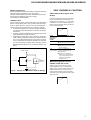
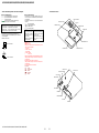
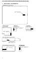
HOW TO OPEN THE TRAY WHEN POWER SWITCH TURN OFF
HOW TO IDENTIFY OPTICAL PICK-UP BLOCK
Printed of KHM-310CAB or KHM-313CAB.
Note: There are two kinds of OPTICAL PICK-UP BLOCK in this set.
When replacing the OPTICAL PICK-UP BLOCK, make sure which
OPTICAL PICK-UP BLOCK it is following the “How to Identify”
in the figure shown below.
OPTICAL PICK-UP BLOCK
gear (BU1)
Turn gear (BU1) from a hole at the bottom,
and pull out a tray.
tray

8
HCD-HDX265/HDX266/HDX267W/HDX465/HDX466/HDX665
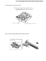
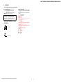
HARNESS SETTING
MAIN BOARD SERVICE POSITION
MAIN board
IO board
back panel
insulation sheet
1
Remove the back panel with
IO board
.
2
Remove the MAIN board.
3
Assemble the MAIN board to back panel block.
4
Reverse the back panel block.
Check not touch the heat sink.
lead pin
lead pin
flexible wire
Check not touch
the heat sink. Check not touch the chassis.

9
HCD-HDX265/HDX266/HDX267W/HDX465/HDX466/HDX665
SECTION 2
GENERAL This section is extracted from
instruction manual.
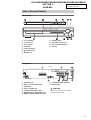
Front panel
A"/1 (on/standby)
BA (open/close)
CDisc operation
DFUNCTION
EFront panel display
F (remote sensor)
GPHONES jack
HVOLUME control
IAUDIO IN/A.CAL MIC jack
JDISC 1-5 buttons/indicators
KDisc tray
Index to Parts and Controls
Rear panel
ASPEAKER jacks
BDIR-TC1 slot for the WAHT-SD1
CAM terminal
DFM 75 Ω COAXIAL jack
ETV/VIDEO (AUDIO IN R/L) jacks
FMONITOR OUT (S VIDEO/VIDEO) jacks
GDMPORT (DIGITAL MEDIA PORT) jack
HCOMPONENT VIDEO OUT jacks
IHDMI OUT jack
*
CAUTION
Please do not remove the screws before
installing the WAHT-SD1.
FRONT R
CENTER WOOFER
FRONT L SUR R SUR L
MONITOR OUT
TV/VIDEO ANTENNA
SPEAKER
DIR-TC1
SPEAKER
COMPONENT VIDEO OUT
COAXIAL
AM
FM
75
RLAUDIO IN
YP
B
/C
B
P
R
/C
R
VIDEO
(DVD ONLY)
S VIDEO
(DVD ONLY)
(DVD ONLY)
OUT
DMPORT
Screws*

10
HCD-HDX265/HDX266/HDX267W/HDX465/HDX466/HDX665
Front panel display
About the indications in the front panel display
ALights up when the HDMI OUT jack is
correctly connected to HDCP (high-
bandwidth digital content protection)
compliant device with HDMI or DVI
(digital visual interface) input.
BLights up when the time information of
a title or chapter appears in the front
panel display. (DVD only)
CLights up when the color system is set
to NTSC. (Asian, Australian, and Middle
Eastern models only)
DLights up when a station is received.
(Radio only)
EStereo/Monaural effect (Radio only)
FLights up when the sleep timer is set.
GLights up when the movie or music
mode is selected.
HPlaying status (DVD function only)
ICurrent repeat mode
JLights up when the child lock function
is set to on.
KLights up when the system outputs
progressive signals (DVD function
only).
LIndicates the selected [SPEAKER
FORMATION].
MCurrent surround format (Except for
JPEG)
NLights up when the DYNAMIC BASS is
selected.
ODisplays system’s status such as
chapter, title, or track number, time
information, radio frequency, playing
status, sound field, etc.
Remote control
ANGLE 5
AUDIO 4
CLEAR ef
D.TUNING wf
DISC SKIP eg
DISPLAY 2
DVD MENU wh
DVD TOP MENU qf
DYNAMIC BASS wd
ENTER wg
FUNCTION ws
MOVIE/MUSIC qj
MUTING 7
Number buttons* qg
PICTURE NAVI 6
PRESET +/− wk es
SOUND FIELD qh
SUBTITLE wf
SYSTEM MENU wg
THEATRE SYNC w;
TUNING +/− 0 qs
TV e;
TV CH +/− wa
TV INPUT qk
TV VOL +/− eh
VIDEO FORMAT 3
VOLUME +/−* 8
[/1 (on/standby) 1
TV [/1 (on/standby) ej
C/X/x/c/ qd
REPLAY/
ADVANCE 9
./> es wk
m/M qs 0
SLOW qs 0
H (play)* ea
STEP 9
x (stop) wl
X (pause) qa
Z (open/close) ql
DISPLAY wj
O RETURN ed
-/-- ef
*The H, number 5, and
VOLUME + buttons have
tactile dots. Use the tactile dots
as references when operating
the system.
ALPHABETICAL ORDER
A – O P – Z
BUTTON RESCRIPTIONS

HCD-HDX265/HDX266/HDX267W/HDX465/HDX466/HDX665
11
•This set can be disassembled in the order shown below.
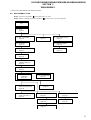
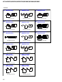
3-1. DISASSEMBLY FLOW
Note 1: The process described in can be performed in any order.
Note 2: Without completing the process described in , the next process can not be performed.
SECTION 3
DISASSEMBLY
SET
3-2. CASE
(Page 12)
3-3. DIAT CON BOARD
(Page 12)
3-4. IO BOARD
(Page 13)
3-5. FRONT PANEL BLOCK
(Page 13)
3-6. POWER BOARD
(Page 14) 3-7. BACK PANEL BLOCK
(Page 14)
3-8. DMPORT BOARD
(Page 15)
3-9. MAIN BOARD
(Page 15)
3-10. COVER (MD)
(Page 16)
3-11. DVD MECHANISM DECK
(CDM81C-DVBU101)
(Page 16)
3-12. TRAY (MAIN) ASSY
(Page 17)
3-13. MOTOR BOARD
(Page 17)
3-14. BASE UNIT
(DVBU101)
(Page 18)
3-15. OPTICAL PICK-UP BLOCK
(KHM-310CAB/313CAB)
(Page 18)
3-16. GEAR (SUB TRAY 1)/
GEAR (SUB TRAY 2)
(Page 19)
3-17. LEVER ASSY
(Page 19)
3-18. STOCKER SECTION
(Page 20)
3-19. CAM (STOCKER)
(Page 20)
3-20. GEAR (STOCKER 3)
(Page 21)
3-21. ROTARY ENCODER (MD)
(Page 21)
3-22. GEAR (BU1)
(Page 22)

HCD-HDX265/HDX266/HDX267W/HDX465/HDX466/HDX665
12
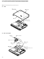
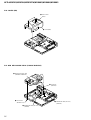
3-3. DIAT CON BOARD
Note: Follow the disassembly procedure in the numerical order given.
3-2. CASE
1
two screws
(case 3 TP2)
2
five screws
(BV3 )
3
two screws
(case 3 TP2
)
4
case
7
case (diat)
8
screw
(BV3)
9
DIAT CON board
6
two screws
(BV3)
5
two screws
(BV3)
3
two screws
(BV3)
4
lid (diat-P)
2
connector
(CN903)
1
flexible flat cable (11 core)
(CN651)

HCD-HDX265/HDX266/HDX267W/HDX465/HDX466/HDX665
13
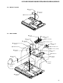
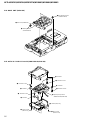
3-4. IO BOARD
3
tuner (FM/AM)
4
flexible flat cable (9 core)
(CN201)
1
flexible flat cable (9 core)
(tuner)
qa
IO board
9
7
flexible flat cable (19 core
)
(CN606)
6
flexible flat cable (5 core)
(CN702)
8
four screws
(BV3)
5
flexible flat cable (11 core)
(CN4302)
2
two screws
(BVTT2.6
×
6)
0
connector
(CN302)
3-5. FRONT PANEL BLOCK
9
screw (BV3)
7
connector (CN3001)
5
two screws
(PWH3
×
8)
4
flexible flat cable (23 core)
(CN501)
6
shield plate (H/P
)
0
three screws
(BV3)
3
loading panel
8
screw
(BV3)
(HDX665)
(HDX665)
1
Turn gear (BU1) from a hole at the bottom,
and pull out a tray.
2
Open the tray.
gear (BU1)
qa
front panel block

HCD-HDX265/HDX266/HDX267W/HDX465/HDX466/HDX665
14
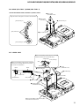
3-7. BACK PANEL BLOCK
3-6. POWER BOARD
7
shield plate (H/P)
6
two screws
(PWH3
×
8)
0
POWER board
4
connector
(CN901)
5
connector
(CN3002)
9
PC board holder
8
two screws
(PWH3
×
8)
1
connector
(CN903)
2
connector
(CN906)
3
connector
(CN907)
8
connector (CN901)
7
connector
(CN3000)
qh
connector
(CN302)
qf
two screws
(BV3)
qg
qd
screw
(BV3)
qs
screw (BV3)
qj
back panel bloc
k
qa
screw (B3
×
6)
0
screw (BV3)
9
two screws
(BV3)
2
flexible flat cable (11 core)
(CN4302)
6
connector
(CN903)
5
flexible flat cable
(19 core) (CN606)
4
flexible flat cable (5 core)
(CN702)
3
flexible flat cable (11 core)
(CN651)
1
flexible flat cable (9 core)
(CN201)

HCD-HDX265/HDX266/HDX267W/HDX465/HDX466/HDX665
15
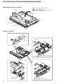
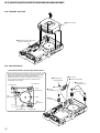
3-8. DMPORT BOARD
2
two screws
(BV3)
1
connector
(CN203)
3
DMPORT board
3-9. MAIN BOARD
qj
two screws
(BV3)
5
connector
(CN625)
qd
connector
(CN906)
4
wire (flat type) (21 core)
(CN626)
6
SIRIPARA board
qf
connector
(CN1201)
qk
four screws
(BV3)
7
screw
(BVTP3
×
12)
8
two screws
(BV3)
9
heat sink (AMP)
qa
wire (flat type)
(24 core)
(CN1101)
0
two radiation sheets
2
two screws
(BV3)
3
SPEAKER board
1
connector (CN780)
ql
two screws
(BV3)
w;
MAIN board
qg
connector
(CN3002)
qh
connector
(CN3001)
qs
wire (flat type)
(23 core)
(CN501)

HCD-HDX265/HDX266/HDX267W/HDX465/HDX466/HDX665
16
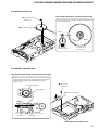
3-11. DVD MECHANISM DECK (CDM81C-DVBU101)
3-10. COVER (MD)
1
four screws
(BV3)
2
cover (MD)
4
five screws
(BVTP3
×
10)
2
flexible flat cable (21 core)
(CN626)
3
connector
(CN1201)
1
flexible flat cable (24 core
)
(CN1101)
5
DVD mechanism deck
(CDM81C-DVBU101)

HCD-HDX265/HDX266/HDX267W/HDX465/HDX466/HDX665
17
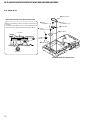
3-13. MOTOR BOARD
3-12. TRAY (MAIN) ASSY
1
two screws
(BTTP M2.6
)
2
two screws
(BTTP M2.6)
3
bracket (top)
4
5
tray (main) assy
1
screw
(BTTP M2.6)
2
bracket
3
screw
(BTTP M2.6)
4
MOTOR board
5
Remove two solders.
6
motor (81) assy (LD/ST motor)
(M761)
7
Remove two solders.
8
motor (81) assy (BU U/D motor)
(M762 )

HCD-HDX265/HDX266/HDX267W/HDX465/HDX466/HDX665
18
3-15. OPTICAL PICK-UP BLOCK (KHM-310CAB/313CAB)
3-14. BASE UNIT (DVBU101)
1
two floating screw
s
(PTPWH M2.6)
2
floating screw
(PTPWH M2.6)
3
base unit (DVBU101)
1
two screws
(BTP2.6
×
8)
2
three screws
(BTTP 2.6)
6
holder (310) assy
4
insulator screw
7
insulator screw
qd
optical pick-up block
(KHM-310CAB/313CAB
)
5
0
insulator
qa
insulator
8
insulator screw
qs
insulator
3
insulator screw
9
insulator

HCD-HDX265/HDX266/HDX267W/HDX465/HDX466/HDX665
19
3-17. LEVER ASSY
3-16. GEAR (SUB TRAY 1)/GEAR (SUB TRAY 2)
1
five screws
(PTPWH2.6
×
8)
2
gear (sub tray 2)
3
gear (sub tray 2)
4
three gears
(sub tray 1)
gear (sub tray 2)
gear (sub tray 2)
gear (sub tray 1)
PRECAUTION DURING GEAR (SUB TRAY 1/2) INSTALLATION
Align the marks of the gears as shown in the illustration.
1
screw
(PTPWH2.6
×
8)
3
floating screw
(PTPWH M2.6)
5
lever (sub tray)
lever (sub tray)
6
lever (release)
lever (release)
7
lever (mode)
cam (BU)
lever (mode)
2
shutter (tray)
4
lever (sub tray)
shutter (tray)
When re-assembling, insert the lever (sub tray)
between the bosses of the shutter (tray).
boss
boss
Before re-assembling, slide the cam (BU)
in the direction of the arrow.
Before re-assembling, align the lever (release)
and the lever (sub tray) with the lever (mode)
as shown in the illustration.
dowel dowel

HCD-HDX265/HDX266/HDX267W/HDX465/HDX466/HDX665
20
3-19. CAM (STOCKER)
3-18. STOCKER SECTION
2
stocker section
1
Rotate the gear (SS3) in the
direction of the arrow.
5
two screws
(PTPWH2.6
×
8)
6
two cams
(stocker)
8
cam
(stocker)
cam (stocker)
cam (stocker)
cam (stocker)
hole
gear
(stocker 2)
gear
(stocker 2)
gear
(stocker 2)
gear (stocker 3)
2
tension spring (SW)
4
lever (SW)
1
floating screw
(PTPWH M2.6)
7
screw
(PTPWH2.6
×
8)
3
hook
PRECAUTION DURING CAM (STOCKER) INSTALLATION
Before installing the cams (stocker), fix the gear (stocker 3) in
the manner so that the hole of the gear (stocker 3) should be
aligned with the hole of the chassis located beneath
the gear (stocker 3). Be sure to install the cams (stocker) in
such a way that the grooves of the cams (stocker) face
the direction of the arrows.
Page is loading ...
Page is loading ...
Page is loading ...
Page is loading ...
Page is loading ...
Page is loading ...
Page is loading ...
Page is loading ...
Page is loading ...
Page is loading ...
Page is loading ...
Page is loading ...
Page is loading ...
Page is loading ...
Page is loading ...
Page is loading ...
Page is loading ...
Page is loading ...
Page is loading ...
Page is loading ...
Page is loading ...
Page is loading ...
Page is loading ...
Page is loading ...
Page is loading ...
Page is loading ...
Page is loading ...
Page is loading ...
Page is loading ...
Page is loading ...
Page is loading ...
Page is loading ...
Page is loading ...
Page is loading ...
Page is loading ...
Page is loading ...
Page is loading ...
Page is loading ...
Page is loading ...
Page is loading ...
Page is loading ...
Page is loading ...
Page is loading ...
Page is loading ...
Page is loading ...
Page is loading ...
Page is loading ...
Page is loading ...
Page is loading ...
Page is loading ...
Page is loading ...
Page is loading ...
Page is loading ...
Page is loading ...
Page is loading ...
Page is loading ...
Page is loading ...
Page is loading ...
Page is loading ...
Page is loading ...
Page is loading ...
Page is loading ...
Page is loading ...
Page is loading ...
Page is loading ...
Page is loading ...
Page is loading ...
Page is loading ...
Page is loading ...
Page is loading ...
Page is loading ...
Page is loading ...
Page is loading ...
Page is loading ...
Page is loading ...
Page is loading ...
Page is loading ...
Page is loading ...
Page is loading ...
Page is loading ...
Page is loading ...
Page is loading ...
Page is loading ...
Page is loading ...
Page is loading ...
Page is loading ...
Page is loading ...
Page is loading ...
Page is loading ...
Page is loading ...
Page is loading ...
Page is loading ...
Page is loading ...
Page is loading ...
Page is loading ...
Page is loading ...
Page is loading ...
Page is loading ...
Page is loading ...
Page is loading ...
Page is loading ...
Page is loading ...
Page is loading ...
Page is loading ...
Page is loading ...
Page is loading ...
Page is loading ...
Page is loading ...
Page is loading ...
Page is loading ...
Page is loading ...
Page is loading ...
Page is loading ...
Page is loading ...
Page is loading ...
Page is loading ...
Page is loading ...
Page is loading ...
Page is loading ...
Page is loading ...
Page is loading ...
Page is loading ...
Page is loading ...
Page is loading ...
Page is loading ...
Page is loading ...
Page is loading ...
Page is loading ...
-
 1
1
-
 2
2
-
 3
3
-
 4
4
-
 5
5
-
 6
6
-
 7
7
-
 8
8
-
 9
9
-
 10
10
-
 11
11
-
 12
12
-
 13
13
-
 14
14
-
 15
15
-
 16
16
-
 17
17
-
 18
18
-
 19
19
-
 20
20
-
 21
21
-
 22
22
-
 23
23
-
 24
24
-
 25
25
-
 26
26
-
 27
27
-
 28
28
-
 29
29
-
 30
30
-
 31
31
-
 32
32
-
 33
33
-
 34
34
-
 35
35
-
 36
36
-
 37
37
-
 38
38
-
 39
39
-
 40
40
-
 41
41
-
 42
42
-
 43
43
-
 44
44
-
 45
45
-
 46
46
-
 47
47
-
 48
48
-
 49
49
-
 50
50
-
 51
51
-
 52
52
-
 53
53
-
 54
54
-
 55
55
-
 56
56
-
 57
57
-
 58
58
-
 59
59
-
 60
60
-
 61
61
-
 62
62
-
 63
63
-
 64
64
-
 65
65
-
 66
66
-
 67
67
-
 68
68
-
 69
69
-
 70
70
-
 71
71
-
 72
72
-
 73
73
-
 74
74
-
 75
75
-
 76
76
-
 77
77
-
 78
78
-
 79
79
-
 80
80
-
 81
81
-
 82
82
-
 83
83
-
 84
84
-
 85
85
-
 86
86
-
 87
87
-
 88
88
-
 89
89
-
 90
90
-
 91
91
-
 92
92
-
 93
93
-
 94
94
-
 95
95
-
 96
96
-
 97
97
-
 98
98
-
 99
99
-
 100
100
-
 101
101
-
 102
102
-
 103
103
-
 104
104
-
 105
105
-
 106
106
-
 107
107
-
 108
108
-
 109
109
-
 110
110
-
 111
111
-
 112
112
-
 113
113
-
 114
114
-
 115
115
-
 116
116
-
 117
117
-
 118
118
-
 119
119
-
 120
120
-
 121
121
-
 122
122
-
 123
123
-
 124
124
-
 125
125
-
 126
126
-
 127
127
-
 128
128
-
 129
129
-
 130
130
-
 131
131
-
 132
132
-
 133
133
-
 134
134
-
 135
135
-
 136
136
-
 137
137
-
 138
138
-
 139
139
-
 140
140
-
 141
141
-
 142
142
-
 143
143
-
 144
144
-
 145
145
-
 146
146
-
 147
147
-
 148
148


Ask a question and I''ll find the answer in the document
Finding information in a document is now easier with AI
Related papers
-
Sony HDX267W User manual
-
Sony HDX267W User manual
-
-
Sony SRS-Z1 User manual
-
Sony HCD-GZR5D Owner's manual
-
Black Box DVP-S3000 Operating Instructions / Mode d’emploi User manual
-
Sony Bravia KDL-52WL130PKG Owner's manual
-
-
-
Other documents
-
Panasonic KX-FG2452CX User manual
-
-
Toshiba SD-P1200 User manual
-
Marantz SR4023 User manual
-
Yamaha RX-V459 - AV Receiver - 6.1 Channel User manual
-
Samsung C3303 User manual
-
 Bartell INNOVATECH HD Vacuum Series Complete Manual
-
Lenovo S920 User manual
-
 Sure Electronics TPA3123 User manual
-

