SAB Heli Division Goblin 500 Sport Owner's manual
- Category
- Remote controlled toys
- Type
- Owner's manual


Goblin 500 Sport Manual
Release 1.0 - Octorber 2015
WORLD DISTRIBUTION
www.goblin-helicopter.com
For sales inquiries, please email:
For info inquiries, please email:
Attention: If you are a consumer and have questions or need of assistance,
please contact in a first time the Goblin retailer where you made the purchase
EUROPEAN DISTRIBUTION
www.sabitaly.it
For sales inquiries, please email:
For info inquiries, please email:
Attention: If you are a consumer and have questions or need of assistance,
please contact in a first time the Goblin retailer where you made the purchase

1011mm
288mm
186mm
Main rotor diameter: 1135mm (with 500mm blades)
Main blade length: 500mm
Tail rotor diameter: 231mm
Tail blade length: 80mm
Main shaft diameter: 10mm
Tail shaft diameter: 5mm
Spindle diameter: 8mm
- Weight including standard electronics: 1880g (excluding batteries).
- Maximum motor size: diameter 52mm, height 58mm
- Battery compartment: 52x53x180mm.
SPECIFICATIONS
Please read this user manual carefully, it contains instructions for the correct assembly of the model.
Please refer to the web site www.goblin-helicopter.com for updates and other important information.
It is extremely important that you take a moment to register your helicopter
with us. This is the only way to ensure that you are properly informed about
changes to your kit, such as upgrades, retrofits and other important
developments. SAB Heli Division cannot be held responsible for issues arising
with your model and will not provide support unless you register your serial
number.
To mount the serial number tag on your helicopter, please refer to page 25.
Thank you for your purchase, we hope you enjoy your new Goblin helicopter!
SAB Heli Division
Inside Box 4, you will find Bag 10 with a red label. This bag contains your serial number tag. Please take a moment to register your
kit online via our web site at:
INDEX
1 – Serial Number
2 – Important Notes
3 – Components and Box
4 – Carbon frame Assembly
5 – Trasmission Assembly
6 – Main rotor
7 – Installation of Servos
8 – Assembling The Modules
9 – Installation of The ESC
10 – Installation of Flybarless Unit and RX
11 – Installation of Motor
12 – Tail Assembly
13 – Installation of the Boom
14 – Battery
15 –
Canopy / Serial number
16 – In flight / Maintenance
17 – Exploded Views
18 – Spare Parts
VERY IMPORTANT
http: //www.goblin-helicopter.com
Page 1
Chapter 1, Serial Number

IMPORTANT NOTES
*This radio controlled helicopter is not a toy.
*This radio controlled helicopter can be very dangerous.
*This radio controlled helicopter is a technically complex device which has to be built and handled very carefully.
*This radio controlled helicopter must be built following these instructions. This manual provides the necessary information
to correctly assemble the model. It is necessary to carefully follow all the instructions.
*Inexperienced pilots must be monitored by expert pilots.
*All operators must wear safety glasses and take appropriate safety precautions.
*A radio controlled helicopter must only be used in open spaces without obstacles, and far enough from people to minimize
the possibility of accidents or of injury to property or persons.
*A radio controlled helicopter can behave in an unexpected manner, causing loss of control of the model, making it very
dangerous.
*Lack of care with assembly or maintenance can result in an unreliable and dangerous model.
*
Neither SAB Heli Division nor its agents have any control over the assembly, maintenance and use of this product.
Therefore, no responsibility can be traced back to the manufacturer. You hereby agree to release SAB Heli Division from
any responsibility or liability arising from the use of this product.
SAFETY GUIDELINES
*Fly only in areas dedicated to the use of model helicopters.
*Follow all control procedures for the radio frequency system.
*It is necessary that you know your radio system well. Check all functions of the transmitter before every flight.
*The blades of the model rotate at a very high speed; be aware of the danger they pose and the damage they may cause.
*Never fly in the vicinity of other people.
NOTES FOR ASSEMBLY
Please refer to this manual for assembly instructions for this model.
Follow the order of assembly indicated. The instructions are divided into chapters, which are structured in a way that
each step is based on the work done in the previous step. Changing the order of assembly may result in additional or
unnecessary steps.
Use thread lockers and retaining compounds as indicated. In general, each bolt or screw that engages with a metal part
requires thread lock.
It is necessary to pay attention to the symbols listed below:
Important
Use retaining
compound
(eg Loctite 648)
Use retaining
compound
(eg Loctite 243)
Use CA Glue
Use Proper
Lubricant
Indicates that for this
assembly phase you need
materials that are in bag xx.
Bag xx
Page 2
Chapter 2, Important Notes

ADDITIONAL COMPONENTS REQUIRED
*Electric Motor: 6S – 900 / 1400Kv
maximum diameter 52mm,
maximum height 58mm, pinion shaft diameter 5 - 6mm
*Speed controller:
minimum 80A, recommended 100A
*Batteries: 6S - 3300-4500mAh
*1 flybarless 3 axis control unit
*Radio power system, if not integrated with the ESC
*3 cyclic servos
*1 tail rotor servo
*6 channel radio control system on 2.4 GHz
(See configuration examples on page 15)
The assembly process is described in the following chapters.
Each chapter provides you with the box, bag and/or foam tray
numbers you will need for that chapter.
The information is printed in a red box in the upper right hand
corner of the page at the beginning of every chapter.
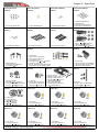
TOOLS, LUBRICANTS, ADHESIVES
*Generic pliers
*Hexagonal driver, size 1.5, 2, 2.5, 3, 4 mm
*4mm T-Wrench
*5.5mm Socket wrench (for M3 nuts)
*7mm Hex fork wrench (for M4 nuts)
*Medium threadlocker (eg. Loctite 243)
*Strong retaining compound (eg. Loctite 648)
*Spray lubricant (eg. Try-Flow Oil)
*Synthetic grease (eg. Tri-Flow Synthetic Grease)
*Grease (eg. Vaseline Grease)
*Cyanoacrylate adhesive
*Pitch Gauge (for set-up)
*Soldering equipment (for motor wiring)
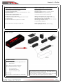
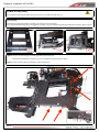
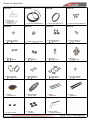
Inside The Box:
Box 1: Canopy, Main Frames, Big Plastic Parts
Blade Holder.
Box2: Optional Combo Components
Box 3: Mechanical Parts in 3 trays:
Tray 1: Head parts
Tray 2: Main structure
Tray 3: Transmission parts
Box 4: Bags
Box 5: Blades, Tail Blades, Boom, Carbon Rod
Inside the box:
Page 3
Chapter 3, In The Box

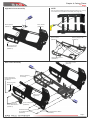
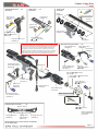
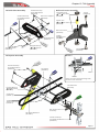
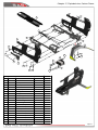
4-Carbon Frame
The manufacturing process of the carbon parts
often leaves micro-burrs and sharp edges.
We recommend de-burring the edges to
minimize the risks of electrical wire cuts, etc.
Page 4
Chapter 4, Carbon Frame

Battery Block
(H0256-S)
Button Head Cap
Screw M2x5mm
(HC005-S)
Battery Support Dx
(H0259-S)
Battery Support Sx
(H0258-S)
Spacer 54mm
(H0239-S)
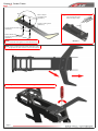
Right Main Frame
Assembly
Main Frame
(H0634-S)
Battery Support
Assembly
Antenna guide
(HA106-S)
Finishing Washer M2.5
(H0255-S)
Socket Head Cap
Screw M2.5x10mm
(HC022-S)
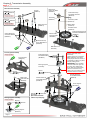
NOTE:
We recommend drilling 4 holes (approximately 2.5 ~ 3 mm)
to facilitate the installation of the ESC ( See page 16 ).
Do not install these bolts yet
Right Main Frame Assembly
Main Frame Assembly
Main Frame
(H0634-S)
Front Lading Gear
(H0638-S)
Socket Head Cap
Screw M2.5x8mm
(HC020-S)
Bag 1
Button Head Cap
Special M2.5x6mm
(HC019-S)
Chapter 4, Carbon Frame
Page 5

C
Note:
Please do not tighten screws M2.5x15mm
Metrix Nylon
Nut M2.5mm
(HC200-S)
Suggestion:
Use a bit CA Glue for
block the Nylon Nut
DETAIL A
Plastic Landing Gear
(H0637-S)
Socket Head Cap
Screw M2.5x15mm
(HC028-S)
Finishing Washer M2.5
(H0255-S)
A
Landing Gear Support
(H0262-S)
Frame Grommet
(HA021-S)
Bag 1
Note:
Insert 1 side first then rotate the other side
to go into the slot and arrive to the stop point.
Note:
Tighten the screws when the landing gear is in the correct position.
Page 6
Chapter 4, Carbon Frame

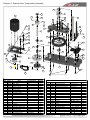
5-Tranmission Assembly
Page 7
Chapter 5 , Tranmission Assembly

Socket Head Cap
Screw M2.5x15mm
(HC031-S)
Bearing
8x
16x5mm
(HC419-S)
Servo Support
(H0627-S)
Metrix Hex
Nylon Nut M3
(HC206-S)
Column
(H0263-S)
Bearing
10x
19x5mm
(HC422-S)
Bearing
8x
16x5mm
(HC419-S)
Socket Head Cap
Screw M2.5x8mm
(HC020-S)
Main Structure
(H0635-S)
Bearing
10x
19x5mm
(HC422-S)
Bearing Support
(H0207-S)
Bearing Support Assembly
Servo Support Assembly
Bearing Support
Assembly
Socket Head Cap
Screw M3x14mm
(HC064-S)
Spacer
10x
16x14.6mm
(H0223-S)
Socket Head Cap
Screw M2.5x8mm
(HC020-S)
Servo Support
Assembly
Washer
8x
14x0.2mm
(HC228-S)
(Use shims if need to
remove any axial play)
Socket Head Cap Screw
Shouldered M3x20mm
(HC082-S)
Metric Hex
Nylon Nut M3
(HC206-S)
Secondary Shaft
(H0221-S)
62T Main Gear
(H0423-S)
Main Shaft
(H0222-S)
18T Pinion
(H0210-S)
Socket Head Cap
Screw M2.5x8mm
(HC020-S)
Socket Head Cap
Screw M2.5x8mm
(HC020-S)
Main Structure Assembly
Main Structure
Assembly
Metric Hex
Nylon Nut M2.5
(HC200-S)
Washer 10x 16x0.1mm
(HC234-S)
Tighten the three screw M3.
After tightening, check the
axial play of the main shaft. It
is possible to reduce any axial
play by adding shims.
IMPORTANT:
Very carefully
check to make sure you can
turn the main shaft freely.
If you feel too much friction,
you have used too many
shims, you can remove a shim
until the shaft turns freely.
Bag 2.1
Page 8
Chapter 5, Transmission Assembly

Socket Head Cap
Screw M2.5x15mm
(HC031-S)
Socket Head Cap
Screw M2.5x6mm
(HC018-S)
48T Pulley
(H0214-S)
Flanged Bearing
8x
12x3.5mm
(HC418-S)
One Way Bearing
8x
12x12mm
(HC440-S)
48T Pulley Assembly
48T Pulley
Assembly
28T Pulley
(H0218-S)
Sensor Support
(H0224-S)
Finishing
Washer M2.5
(H0255-S)
Socket Head Cap
Screw M2.5x8mm
(HC020-S)
Swashplate
Anti-Rotation Guide
(H0643-S)
Note: Small Diameter Facing UP
Flanged Bearing
8x
12x3.5mm
(HC418-S)
Bags 2.2, 2.3, 2.4
eg: Microlube GL621
[HC228]
Page 9
Chapter 5, Transmission Assembly

6-Main Rotor
Page 10
Chapter 6,
Main Rotor

Spindle
(H0213-S)
Uniball Radius Arm ... x 2
Assembly
Main Blade Grip Assembly
....x2
Note
: Larger ID inside
Button Head Cap
Screw M6x10mm
(HC122-S)
[H0225-S]
Oring
(HC330-S)
Washer
6x
12 x1mm
(HC193-S)
Thrust Bearing
8x
14x4mm
(HC437-S)
Washer
2.5x4x0.3mm
(HC172-S)
Linkage Rod A Assembly . . . . .x2
Center Hub
Assembly
Radius Arm
(H0204-S)
Uniball Radius Arm
(H0205-S)
Flanged Bearing
2.5x
6x2.5mm
(HC400-S)
Flanged Bearing
2.5x
6x2.5mm
(HC400-S)
Spacer Arm
2.5x4x6.3mm
(H0253)
Spacer Arm
2.5x4x3mm
(H0254)
Main Blade Grip
Assembly
Bearing
8x
14x4mm
(HC417-S)
Radius Arm ... x 2
Assembly
Linkage Rod
M2.5x33mm
(H0237-S)
Approx. 62mm
Oring
(HC330-S)
Socket Head Cap
Screw M2.5x18mm
(HC032-S)
Main Blade Arm
(H0203-S)
Socket Head Cap
Screw M3x8mm
(HC050-S)
Spacer
11x
13.8x0.5mm
(H0226-S)
Socket Head Cap
Screw M2.5x15mm
(HC028-S)
Linkage Ball Link
(H0066-S)
(Initial length for the rods from the swashplate
to the blade grip.)
Left Thread
Right Thread
Bearing
8x
14x4mm
(HC417-S)
Center Hub
(H0206-S)
Main Blade Grip
(H0202-S)
Uniball M3
(H0065-S)
Linkage Ball Link
(H0066-S)
Linkage Rod A
Assemly
Radius Arm
Assembly
(H0204-S)
eg: Microlube GL261
eg: Microlube GL261
Bag 3
NOTE:
We recommend assembling without shims for sport flying.
The HPS head should be assembled with one 1mm spacer H0225
on each side. After approximately 10/20 flights, please check
preload, you can add one or two shim HC228 if preload has
changed. For hard 3D, the best setup is add one extra shim
between the spacer H0225 and bearing. Important is that the
blade grips must move freely, but they should not move just
under their own weight. You can find HC228 in the Bag 11.
Page 11
Chapter 6, Main Rotor

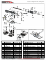
Servo Mounting Options Medium Size Servo
H0064-S
HC008-S
H0251-S
SERVO
H0245-S
HC022-S
H0064-S
H0031-S
HC008-S
HC022-S
H0245-S
SERVO
H0251-S
H0251-S
SERVO
H0245-S
HC022-S
HC008-S
H0064-S
HC022-S
H0245-S
SERVO
H0251-S
H0031-S
HC008-S
H0064-S
34mm
Note: Please Remove
36mm
120°
120°
18.5mm
Servo 1
Servo 2
Servo 3
X
X
X
X
41mm
X
X
X
X
120°
120°
18.5mm
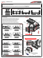
Installation Of The Swashplate Servos
The distance between the center of the horn and the ball should be between
16-18 mm (Figure 1)
.
Select the carbon fiber servo mount that is suitable for the size of servos to be used
(Figrure 2)
.
H0245 H0246
Servo 2
Servo 3
Servo 1
Front
Socket Head Cap
Screw M2.5x8mm
(HC020-S)
Servo Mounting
The servo linkages must be aligned correctly. In order to do
this, you must chose from one of the options shown here.
Figure 3 shows the installation of the servos at 120 degrees.
Note that the distance between the carbon fiber servo
mount and the center of the ball should be 18.5mm.
Figure 4 and figure 5 shows 8 different mounting options,
the distance “X” should be as close as possible to 18.5mm.
Final Servo Assembly
Note:
Chamfer Outside In Carbon Parts
16-18mm
Bag 4
H0308
H0064-S
HC004-S
H0392-S
SERVO
H0308-S
HC022-S
HC022-S
H0308-S
SERVO
H0392-S
H0064-S
H0031-S
HC008-S
H0064-S
HC004-S HC022-S
H0308-S
SERVO
H0392-S
H0392-S
SERVO
H0308-S
HC022-S
H0064-S
H0031-S
HC008-S
Servo Mounting Options Full Size Servo
Page 12
Chapter 7, Installation Servo

Servo Spacer
(H0075-S)
Socket Head Cap
Screw M2x6mm
(HC004-S)
Tail Servo Assembly
15-17mm
The distance between the
center of the horn and the ball
should be between 15-17 mm.
Uniball M2
5H6
(H0064-S)
Tail Servo
Socket Head Cap
Screw M2.5x12mm
(HC026-S)
Tail Servo
Socket Head Cap
Screw M2.5x8mm
(HC020-S)
Finishing
Washer M2.5
(H0255-S)
Socket Head Cap
Screw M2.5x8mm
(HC020-S)
Canopy Positioner
(H0217-S)
Socket Head Cap
Screw M2.5x8mm
(HC020-S)
Finishing
Washer M2.5
(H0255-S)
Canopy Positioner
(H0217-S)
Socket Head Cap
Screw M2.5x8mm
(HC020-S)
Bag 4, Bag 5
Page 13
Chapter 7, Installation Servo

Swashplate Assembly
Uniball M3
(H0063-S)
Uniball M3
(H0065-S)
Set Screw
M2.5x15mm
(HC146-S)
Linkage Rod B Assembly . . . . .x3
(Initial length for the rods from the servos to the swash plate.)
(Initial length for the rods from the swash plate to the Blade Grip.)
Linkage Rod A Assembly . . . .x2
Approx. 62mm
Linkage Rod M2.5x33mm
(H0237-S)
Plastic Ball Link
(H0066-S)
Linkage Rod B
Assembly
Linkage Rod A
Assembly
Socket Head Cap Screw
Shouldered M3x20mm
(HC082-S)
Socket Head Cap
Screw M2.5x12mm
(HC026-S)
Metric Hex
Nylon Nut M3
(HC206-S)
Approx. 44.5mm
Swashplate
Assemly
Plastic Ball Link
(H0066-S)
Swashplate
Assemly
(H0477-S)
Preliminary Head Setup
Adjust the linkages as shown. You can change the tracking
without disconnecting the plastic ball links by inserting a small
tool through the rod hole and turning it.
Left Thread
Right Thread
Socket Head Cap
Screw M2.5x12mm
(HC026-S)
Approx.
35.5mm
Bag 5
Approx.
53mm
Page 14
Chapter 8, Assembling The Modules

Some example configurations:
Battery
Pinion
a,b,c
Gov
ESC
RPM Max
a,b,c
Pitch
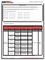
Note: Although the Goblin can fly at high RPM, for safety reasons we recommend not exceeding 2900 RPM.
Motor
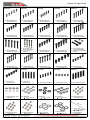
It is important to choose the right reduction ratio to maximize efficiency based on your required flight performance.
The Goblin has many possible reduction ratios at your disposal. It is possible to optimize any moror and battery combination.
It is recommended to use wiring and connector appropriate for the currents generated in a helicopter of this class.
If you are using a head speed calculator which requires a main gear and pinion tooth count, use 165 teeth for main gear
(this takes into account the two stage reduction) and the tooth count of your pulley as the pinion count.
Below is a list of available reduction ratios:
H0215-15-S-15T Pinion = ratio 11:1 H0215-20-S-20T Pinion = ratio 8.26:1
H0215-16-S-16T Pinion = ratio 10.33:1 H0215-21-S-21T Pinion = ratio 7.87:1
H0215-17-S-17T Pinion = ratio 9.72:1 H0215-22-S-22T Pinion = ratio 7.51:1
H0215-18-S-18T Pinion = ratio 9.18:1 H0215-23-S-23T Pinion = ratio 7.19:1
H0215-19-S-19T Pinion = ratio 8.7:1 H0215-24-S-24T Pinion = ratio 6.91:1
These are pulleys for motors with a 6 mm shaft. Each pulley includes an adapter for motors with a 5 mm shaft.
TRANSMISSION SETUP
GOBLIN 500 SPORT CONFIGURATIONS
6S
3300/4500
Pyro 600-1200
CC Edge 100
18T / 19T
SET RPM
2600 / 2700 / 2850
12.5
HW-100A-V3
Jive 100LV
YGE 120 LVK
17T / 18T
Gov @ 80%
Quantum
4120-1200
CC Edge 100
18T / 19T / 20T
SET RPM
HW-100A-V3
Jive 100LV
YGE 120 LVK
17T / 18T / 19T
Gov @ 80%
Scorpion
HK 4020-1100
CC Edge 100
19T / 20T /21T
SET RPM
HW-100A-V3
Jive 100LV
YGE 120 LVK
18T / 19T / 20T
Gov @ 80%
X-Nova
4020-1200
CC Edge 100
18T / 19T / 20T
SET RPM
HW-100A-V3
Jive 100LV
YGE 120 LVK
17T / 18T / 19T
Gov @ 80%
KDE
550XF-1200-G3
CC Edge 100
18T / 19T / 20T
SET RPM
HW-100A-V3
Jive 100LV
YGE 120 LVK
17T / 18T / 19T
Gov @ 80%
Scorpion
HK 4025-1100
CC Edge 100
20T /21T / 22T
SET RPM
HW-100A-V3
Jive 100LV
YGE 120 LVK
19T / 20T /21T
Gov @ 80%
Page 15
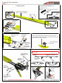
Chapter 9, Installation Of The ESC

De-Burr The Side Frames
We recommend de-burring the edges of the carbon parts in areas where electrial wires run.
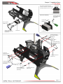
ESC Installation
The electronic speed control (ESC) is intalled in the front part of the helicopter.
If you have drilled the 4 holes (Fig 1) as suggested on page 5, you can easily fasten the ESC with cable ties as shown in figures 2 and 3.
Figure 4:
You can see the wiring for connecting the ESC to the central unit.
Route the ESC throttle wire as shown, you can use cable ties to keep the wire in place.
Figure 5:
You can install a BEC ( or 2S battery ) if required as shown.
Page 16
Chapter 9, Installation Of The ESC

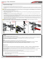
FBL Assembly
Socket Head Cap
Screws M2.5x6mm
(HC018-S)
Finishing Washer
M2.5
(H0255-S)
FBL
Double- sided Tape
FBL support
(H0250-S)
1
2
3
4
FBL System Installation
We recommend the use of a one unit flybarless system, i.e. Mini vBar, Vortex, Microbeast, etc.
However, a two unit flybarless system can also be installed. For one unit systems, the unit is installed as shown in position 1 (Fig 1)
Two unit systems can be installed as follows: control unit in position 1 and sensor in position 2 or vice-versa. (Fig 1). See Fig 2, 3 & 4.
Position 3 and 4 can be used for a Spektrum sattelite. (Fig 1)
Bag 6
Note: We recommend de-burring
the edges of the support H0250.
Page 17
Chapter 10, Installation of FBL and RX

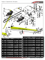
15°
5mm
5mm
Set Screw
M4x4mm
(HC152-S)
Flat Head Cap
Screw M3x5mm
(HC132-S)
18T Pulley
(H0215-18-S)
(See page 15 for additional
pulleys available)
Socket Head Cap
Screw M2.5x8mm
(HC020-S)
Washer
4.3x
11x1mm
(HC184-S)
Metric Hex Nylon Nut M4H5
(HC212-S)
Spring de 5 / df 0.3 / LL6
(HC316-S)
Note:
To maximize space for the batteries, it is advisable to shorten the motor shaft.
Follow the dimensions given in this drawing.
For the cut, you can use an electric tool like a “Dremel” with a cut-off disc.
Additionally, ensure the motor shaft has an appropriate 'flat' for one of the set screws.
Motor Support
(H0211-S)
Set Screw
M4x15mm
(HC154-S)
Finishing
Washer M2.5
(H0255-S)
Bushing
5x
6x18mm
(H0266-S)
(Needed with 5 mm motor shaft)
23mm
Socket Head Cap
Screw M2.5x8mm
(HC020-S)
Spring
de 3 / df 0.53 / LL35
(HC311-S)
Note:
Recommended motor
wiring orientation
Bag 6
Page 18
Chapter 11, Installation of The Motor
Page is loading ...
Page is loading ...
Page is loading ...
Page is loading ...
Page is loading ...
Page is loading ...
Page is loading ...
Page is loading ...
Page is loading ...
Page is loading ...
Page is loading ...
Page is loading ...
Page is loading ...
Page is loading ...
Page is loading ...
Page is loading ...
Page is loading ...
Page is loading ...
Page is loading ...
Page is loading ...
-
 1
1
-
 2
2
-
 3
3
-
 4
4
-
 5
5
-
 6
6
-
 7
7
-
 8
8
-
 9
9
-
 10
10
-
 11
11
-
 12
12
-
 13
13
-
 14
14
-
 15
15
-
 16
16
-
 17
17
-
 18
18
-
 19
19
-
 20
20
-
 21
21
-
 22
22
-
 23
23
-
 24
24
-
 25
25
-
 26
26
-
 27
27
-
 28
28
-
 29
29
-
 30
30
-
 31
31
-
 32
32
-
 33
33
-
 34
34
-
 35
35
-
 36
36
-
 37
37
-
 38
38
-
 39
39
-
 40
40


SAB Heli Division Goblin 500 Sport Owner's manual
- Category
- Remote controlled toys
- Type
- Owner's manual
Ask a question and I''ll find the answer in the document
Finding information in a document is now easier with AI
Related papers


Other documents
-
Savoy House 7-1639-6 User manual
-
 KinAn MKDN-19T User manual
-
 Geeek A50 PLUS Installation guide
-
Compass 7hv User manual
-
peak design M-MM-AD-BK-WEB-1 Mobile Motorcycle Mount 1 Inch Ball Adapter Operating instructions
-
 Mikado VBar NEO Quick start guide
-
Deagostini 3D Printer idbox User guide
-
 Hover-1 Jive Owner's manual
-
 Hover-1 HOVER-1 H1-JVE JIVE Electric Folding Scooter User manual
-
 Heli Artist 600 Scale Fuselage B0105 User manual


