Page is loading ...


2
Disclaimer
Specifications written in this document are believed to be accurate, but are not guaranteed to
be entirely free of error. The information in this manual is subject to change for functional or
performance improvements without notice. Please make sure your manual is the latest edition.
While the information herein is assumed to be accurate, SEGGER Microcontroller GmbH (SEG-
GER) assumes no responsibility for any errors or omissions. SEGGER makes and you receive no
warranties or conditions, express, implied, statutory or in any communication with you. SEGGER
specifically disclaims any implied warranty of merchantability or fitness for a particular purpose.
Copyright notice
You may not extract portions of this manual or modify the PDF file in any way without the prior
written permission of SEGGER. The software described in this document is furnished under a
license and may only be used or copied in accordance with the terms of such a license.
© 2004-2017 SEGGER Microcontroller GmbH, Hilden / Germany
Trademarks
Names mentioned in this manual may be trademarks of their respective companies.
Brand and product names are trademarks or registered trademarks of their respective holders.
Contact address
SEGGER Microcontroller GmbH
In den Weiden 11
D-40721 Hilden
Germany
Tel. +49 2103-2878-0
Fax. +49 2103-2878-28
E-mail: [email protected]
Internet: www.segger.com
J-Link-OB-STM32F103 User Guide (UM08023) © 2004-2017 SEGGER Microcontroller GmbH

3
Manual versions
This manual describes the current version. If you find an error in the manual, please report it to
us and we will try to assist you as soon as possible.
Contact us for further information on topics that are not yet documented.
Print date: January 18, 2018
Manual
version
Revision Date By Description
0.00 1 171012 NG
Initial Version
J-Link-OB-STM32F103 User Guide (UM08023) © 2004-2017 SEGGER Microcontroller GmbH

4
J-Link-OB-STM32F103 User Guide (UM08023) © 2004-2017 SEGGER Microcontroller GmbH

5
About this document
Assumptions
This document assumes that you already have a solid knowledge of the following:
• The software tools used for building your application (assembler, linker, C compiler).
• The C programming language.
• The target processor.
• DOS command line.
If you feel that your knowledge of C is not sufficient, we recommend The C Programming Lan-
guage by Kernighan and Richie (ISBN 0–13–1103628), which describes the standard in C pro-
gramming and, in newer editions, also covers the ANSI C standard.
How to use this manual
This manual explains all the functions and macros that the product offers. It assumes you have
a working knowledge of the C language. Knowledge of assembly programming is not required.
Typographic conventions for syntax
This manual uses the following typographic conventions:
Style Used for
Body Body text.
Keyword
Text that you enter at the command prompt or that appears on
the display (that is system functions, file- or pathnames).
Parameter Parameters in API functions.
Sample Sample code in program examples.
Sample comment Comments in program examples.
Reference
Reference to chapters, sections, tables and figures or other doc-
uments.
GUIElement Buttons, dialog boxes, menu names, menu commands.
Emphasis Very important sections.
J-Link-OB-STM32F103 User Guide (UM08023) © 2004-2017 SEGGER Microcontroller GmbH

6
J-Link-OB-STM32F103 User Guide (UM08023) © 2004-2017 SEGGER Microcontroller GmbH

7
Table of contents
1 Why J-Link OB? ............................................................................................................8
2 Supported target CPU cores ........................................................................................ 9
3 Supported target interfaces ........................................................................................ 10
3.1 Target interface pins .....................................................................................11
3.2 Target interface JTAG ................................................................................... 12
3.3 Target interface SWD ....................................................................................13
4 Compatible MCUs as J-Link OB host .........................................................................14
5 Schematics ..................................................................................................................15
6 Glossary ......................................................................................................................16
J-Link-OB-STM32F103 User Guide (UM08023) © 2004-2017 SEGGER Microcontroller GmbH

Chapter 1
Why J-Link OB?
The J-Link on-board (J-Link OB) was designed in order to provide a low-cost, space-saving
and on-board alternative to the general J-Link, for eval board manufacturers. J-Link OB can
be used with the same software package as the general J-Links and can be used with the
same utilities (as far as the feature set of the J-Link OB supports this)
Note
It is not allowed to use J-Link-OB-STM32F103 for stand-alone emulators.
J-Link-OB-STM32F103 User Guide (UM08023) © 2004-2017 SEGGER Microcontroller GmbH


Chapter 3
Supported target interfaces
The J-Link-OB-STM32F103 supports the following target interfaces:
• JTAG
• SWD (+ SWO)
It may therefore be used for ARM7/9 target CPUs or other target CPUs with JTAG connection
or Cortex-M targets with JTAG or Serial Wire Debug connection.
J-Link-OB-STM32F103 User Guide (UM08023) © 2004-2017 SEGGER Microcontroller GmbH

11 CHAPTER 3 Target interface pins
3.1 Target interface pins
The J-Link-OB-STM32F103 provides the following target interface signals:
• TCK/SWCLK (PA5 / Pin 15)
• TMS/SWDIO (PA7 / Pin 17)
• TDI (PA2 / Pin 12)
• TDO/SWO (PA10 / Pin 31)
• #RESET (PA1 / Pin 11)
• nTRST (PA0 / Pin 10)
Which signals are required depends on what features shall be supported on the evaluation
board. If support for a specific feature or interface is not required, the spare pins should be
left open. For more information about which target interface requires which signals, please
refer to the following sections.
J-Link-OB-STM32F103 User Guide (UM08023) © 2004-2017 SEGGER Microcontroller GmbH

12 CHAPTER 3 Target interface JTAG
3.2 Target interface JTAG
If JTAG support is required on the target hardware to be designed, the following signals
need to be connected:
• TCK (PA5 / Pin 15)
• TMS (PA7 / Pin 17)
• TDI (PA2 / Pin 12)
• TDO (PA10 / Pin 31)
• #RESET (PA1 / Pin 11)
• nTRST (PA0 / Pin 10)
Note
TCK and TMS share functionality with the SWCLK and SWDIO pins used for the SWD
interface. So if JTAG connected on the J-Link OB, SWD is supported automatically as
well.
J-Link-OB-STM32F103 User Guide (UM08023) © 2004-2017 SEGGER Microcontroller GmbH

13 CHAPTER 3 Target interface SWD
3.3 Target interface SWD
If SWD (+ optional SWO) support is required on the target hardware to be designed, the
following signals need to be connected:
• SWCLK (PA5 / Pin 15)
• SWDIO (PA7 / Pin 17)
• SWO (PA10 / Pin 31)
• #RESET (PA1 / Pin 11)
If SWO support is not required (e.g. when the target CPU is Cortex-M0/M0+ based, which
does not provide SWO support), the SWO signal can be left open.
J-Link-OB-STM32F103 User Guide (UM08023) © 2004-2017 SEGGER Microcontroller GmbH

Chapter 4
Compatible MCUs as J-Link OB
host
The J-Link-OB-STM32F103 is based on the ST STM32 F103 72 MHz, 128 KB flash, 20 KB
RAM series MCUs. The following microcontrollers are compatible to this J-Link OB model:
• STM32F103CB (LQFP48, UFQPN48, VFQFPN48)
• STM32F103RB (LQFP64, TFBGA64)
• STM32F103TB (VFQFPN36)
• STM32F103VB (LFBGA100, LQFP100, UFBGA100)
J-Link-OB-STM32F103 User Guide (UM08023) © 2004-2017 SEGGER Microcontroller GmbH

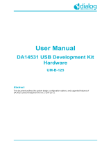
Chapter 5
Schematics
1
1
2
2
3
3
4
4
D D
C C
B B
A A
SEGGER
www.segger.com
J-Link
TM
Technology
Title
Size
Date:
File:
Revision
Sheet
Drawn:
A4
History / Changes
Number
J-Link-OB-STM32F103
Rev. 1.5
VK
1 1
-
/06.11.2013
J_Link_OB_STM32F103_Rev1.5.SchDoc
TCKout
DDP
TMSout
TRSTout
TDIout
DDM
TDOin
TRESout
XIN
XOUT
GND
GND
GND
VDD, VDDA decoupling
ATTACH
LED
VCC3
(see left)
X1
8MHz
BOOT0
44
NRST
7
OSC_IN/PD0
5
OSC_OUT/PD1
6
PA0-WKUP
10
PA1
11
PA2
12
PA3
13
PA4
14
PA5
15
PA6
16
PA7
17
PA8
29
PA9
30
PA10
31
PA11
32
PA12
33
PA13/JTMS/SWDIO
34
PA14/JTCK/SWCLK
37
PA15/JTDI
38
PB0
18
PB1
19
PB2/BOOT1
20
PB3/JTDO
39
PB4/JNTRST
40
PB5
41
PB6
42
PB7
43
PB8
45
PB9
46
PB10
21
PB11
22
PB12
25
PB13
26
PB14
27
PB15
28
PC13-TAMPER-RTC
2
PC14-OSC32_IN
3
PC15-OSC32_OUT
4
VBAT
1
VDD_1
24
VDD_2
36
VDD_3
48
VDDA
9
VSS_1
23
VSS_2
35
VSS_3
47
VSSA
8
U2
STM32F103CBT6
D1
LTST-C170KGKT
J2
JTAG Disable
JTAG Selection
TRST
TDI
TMS
TCK
TDOin
GND
C2
100n
C3
100n
C4
100n
C5
100n
C1
100n
C11
100n
C7
22p*
C8
22p*
* values depend on selected crystal and layout
C6
10n
R12
10k
GND
R9
22R
R10
22R
R11
1k5
R8
1M*
R3
130R
R4
130R
R5
130R
R6
130R
R1
47k
R2
220R
VCC3
GND
* Note:
Pins PB8-15, PC13-15, and VBAT are not present in
VFQFPN36 package.
VCC3
*
*
*
*
*
*
*
*
*
*
*
*
RESET
GND
TCKout
DDP
TMSout
TRSTout
TDIout
DDM
TDOin
XIN
XOUT
ATTACH
LED
GND
Target MCU
USB
TRESout
TDOS
TDIS
TCKS
TMSS
RESET
VCC3
GND
V5
JTAG on board programming connector
RESET
TDIS
TDOS
1
2
3
4
5 6
7
8
9
10
TagConnect
J3
TC2050-IDC
TDOS
TDIS
TCKS
TMSS
TRSTS
TRSTS
Tag-Connect connector for SEGGER J-Link with
J-Link adapter from SEGGER allows supply of the
target board (V5) during programming and
debugging.
GND
Optional "JTAG Disable" jumper.
If JTAG-Disable is not needed, leave PB5 open.
TRSTS
PB5
GND
R7
130R
VCC3
J2 added, R3,R4,R5,R6,R7 changed to 130 Ohm
History / Changes
Rev. 1.0:
Rev. 1.1:
Shield1
S1
Shield2
S2
Vbus
1
D-
2
D+
3
GND
4
J1
USB_BP
VBUS
May be used to supply
5V to the board.
3.3V
VCC3
V5
Rev. 1.2:
Rev. 1.3:
Inital version
R13, R14, R15 removed
Changed MCU connections to allow use of 36 pin package
Added programming connector J3, added C11
Removed U1, C9, C10
Supply
Rev. 1.4: Extended target signal naming for SWD, added note
(See manual for
connection of
target signals)
TDO/SWO
nRESET
TCK/SWCLK
TMS/SWDIO
TDI
nTRST
Rev. 1.5: Moved TDOin from PA6 to PA10
J-Link-OB-STM32F103 User Guide (UM08023) © 2004-2017 SEGGER Microcontroller GmbH

Chapter 6
Glossary
This chapter describes important terms used throughout this manual.
J-Link-OB-STM32F103 User Guide (UM08023) © 2004-2017 SEGGER Microcontroller GmbH

17 CHAPTER 6
Adaptive clocking
A technique in which J-Link / J-Trace sends out a clock signal and waits for the returned
clock from the target device before generating the next clock pulse. The technique allows
the J-Link / J-Trace interface unit to adapt to different signal drive capabilities, different
cable lengths and variable target clock speeds. Adaptive clocking can be used when it is
supported by the connected target device.
RESET
Abbreviation of System Reset. The electronic signal which causes the target system other
than the TAP controller to be reset. This signal is also known as “nSRST” “nSYSRST”, “nRST”,
or “nRESET” in some other manuals. See also nTRST.
nTRST
Abbreviation of TAP Reset. The electronic signal that causes the target system TAP controller
to be reset. This signal is known as nICERST in some other manuals. See also nSRST.
RTCK
Returned TCK. The signal which allows Adaptive Clocking.
TCK
The electronic clock signal which times data on the TAP data lines TMS, TDI, and TDO.
TDI
The electronic signal input to a TAP controller from the data source (upstream). Usually,
the TDI signal of J-Link is connected to the TDI of the first TAP controller in a JTAG chain.
TDO
The electronic signal output from a TAP controller to the data sink (downstream). Usually,
the TDO signal of J-Link is connected to the TDO of the last TAP controller in a JTAG chain.
TMS
The electronic signal Test Mode Select is an input to the TAP controller and it is used to
select different stages of state machine. It is clocked in into the TAP controller using the
TCK signal.(upstream). Usually, the TMS output signal of J-Link is connected to the TMS
input of the first TAP controller in a JTAG chain. For Cortex-M CPUs this signal may also
be used as the bidirectional data signal SWDIO when the CPU is accessed in serial wire
debug mode SWD.
SWD
A serial communication protocol for Cortex M CPUs which may used for communication with
a debug device as an alternative communication channel to JTAG. The SWD communication
uses less pins.
SWDIO
The bidirectional electronic signal for communication of a Cortex M CPU accessed in serial
wire debug mode. Normally, the TMS input pin of the Cortex M CPU is used as SWDIO pin
in serial wire mode.
SWCLK
The electronic signal which times data on the SWDIO data line used in serial wire debug
mode. The SWCLK pin is typically the TCK pin used as JTAG clock input, when JTAG is also
supported by the device.
J-Link-OB-STM32F103 User Guide (UM08023) © 2004-2017 SEGGER Microcontroller GmbH

18 CHAPTER 6
SWO
The electronic asynchronous signal for trace data output or SWV output data which may
be sent by the application on a Cortex-M CPU running in serial wire debug mode. J-Link-
OB-STM32F103 is able to receive the data in asynchronous mode when SWO of the target
CPU is connected to the SWOin signal of J-Link-OB-STM32F103. Normally the SWO output
signal of a Cortex-M CPU is directed via the TDO signal pin, but may be separated on some
devices.
J-Link-OB-STM32F103 User Guide (UM08023) © 2004-2017 SEGGER Microcontroller GmbH
/