
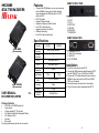
HDMI
EXTENDER
HX-RW
(Remote)
HX-SRW
(Remote)
USER MANUAL V1.0
HX-RW/HX-SRW
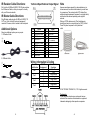
Package Contents-
1x HX-RW or HX-SRW Remote Unit
1 user manual
1x Power adapter DC 12V with lock
1x IR Blaster Cable(Peak Wavelength 940nm)
1x IR Receiver Cable
2x screws
4x foot pads
Any thing missed, please contact with your vendor.
Features
Through the HDMI Extender, you can use one source
device (HDBaseT output port) to display identical
image and extension of HDMI signal up to 100/70
meter on HDTV
HDCP Compliant
Supports 3D pass-through
Supports all frequency band IR control
One CAT.5 cable extension
Supports resolution up to 4Kx2K
HDBaseT technology
Use CAT.5 cable to install easily
Specifications
Function HX-RW HX-SRW
HDMI Out
Connector
HDMI A-Type Female x 1
RJ-45
Connector
1
IR OUT 3.5ψ Stereo Jack x 1
IR2 IN 3.5ψ Stereo Jack x 1
Max.
Resolution
4Kx2K
Cable Distance
100 m 70 m
Power Adapter
(Min.)
DC 12V with lock
Housing Metal
Weight 308g
Dimensions
(LxWxH)
150x80x25 mm
-1-
REMOTE FRONT VIEW
1. IR2 IN
2. IR OUT
3. IR1 IN
4. HDCP LED
5. LINK LED
6. MODE LED
7. POWER LED
REMOTE REAR VIEW
1. Power jack (12V DC)
2. LINK (RJ-45 Connector)
3. HDMI OUT
4. F/W UPGRADE
Installation
1. Turn off the source device and HDTV.
2. Connect the HDMI extension cable between the HDTV
and the “HDMI OUT” port of HX-RW(or HX-SRW).
3. Connect the CAT.5 cables between the source device
(HDBaseT output port) and the HX-RW(or HX-SRW)
“LINK” port of extender.
4. Connect the power cord and turn on the extender.
5. Turn on the source device (equipment) and HDTV.
-2-

IR Receiver Cable Directions:
Put it into the HX-RW(or HX-SRW) “IR2 IN” port and place
the IR Receiver Cable, so that you can point to it easily
with your IR remote controller.
IR Blaster Cable Directions:
Plug IR blaster cable plug into HX-RW(or HX-SRW) “IR
OUT” port, It sits in front of the device (equipment)
receiver’s IR sensor, which is located on the front-panel.
Additional Options
Select any additional options you may require.
1. IR Receiver Cable
GND
+V
Sig
2. IR Blaster Cable
NC
P+
N-
-3-
Technical Specifications Output Signal
Pin #
Signal
Pin #
Signal
1
TMDS Data 2+
11
TMDS Clock Shield
2
TMDS Data 2 Shield
12
TMDS Clock -
3
TMDS Data 2-
13
CEC
4
TMDS Data 1+
14
Reserved
(N.C. on device)
5
TMDS Data 1 Shield
15
SCL
6
TMDS Data 1-
16
SDA
7
TMDS Data 0+
17
DDC/CEC Ground
8
TMDS Data 0 Shield
18
+5V Power
9
TMDS Data 0-
19
Hot Plug Detect
10
TMDS Clock+
Wiring Information & Coding
Conductor
Identification
RJ45 Pin
Assignment
Color C
ode for
Conductor
Pair 1
5 White-Blue
4 Blue
Pair 2
1 White-Orange
2 Orange
Pair 3
3 White-Green
6 Green
Pair 4
7 White-Brown
8 Brown
-4-
Note
However sometimes, especially in demonstrations or in a
lab environment, the cable is rolled randomly in small turns
for convenience. The randomly rolled UTP cable suffers
additional signal impairments (compared to a straight cable)
and therefore the maximal operating reach might be
reduced.
Rolling a CAT5E cable around a 70cm fixed diameter
plastic drum has just a minor effect on the FEXT (Far End
Cross Talk) when compared to a fully stretched
cable.
© C&C TECHNIC TAIWAN CO., LTD. All rights reserved.
Trademarks:
All the companies, brand names, and product names
referred to this manual are the trademarks or registered
trademarks belonging to their respective companies.
-5-
-
 1
1
-
 2
2


Ask a question and I''ll find the answer in the document
Finding information in a document is now easier with AI
Related papers
-
AVLink HDMI-EXW Owner's manual
-
-
-
-
-
-
-
-
-
Other documents
-
 Weltron WA-612E User manual
-
Apantac HDBT-SET-1 User manual
-
CYP PU-507TX-1H User manual
-
CYP PUV-1610TX User manual
-
-
-
-
Comprehensive CHE-HDBT2020 User manual
-
-
CYP PU-HBTE-ZE User manual
