Tripp Lite B064-016-02-IPG User manual

Category
Networking
Type
User manual
1
Quick Start Guide
Table of Contents
1. Hardware Setup 2
1.1 Rack Mounting 2
1.2 Single-Stage Installation 2
1.3 Two-Stage Installation 3
2. Super Administrator Setup 4
2.1 First Time Setup 4
2.2 Network Setup - IP Address Determination 4
2.3 NIC Settings 5
2.4 Changing the Super Administrator Login 6
3. Accessing the B064-Series KVM Switches 6
3.1 Local Console Login 6
3.2 Browser Login 6
3.3 AP Windows Client Login 7
3.4 The Connection Screen 7
3.5 The File Menu 8
3.6 AP Java Client Login 8
4. Warranty & Warranty Registration 8
1111 W. 35th Street, Chicago, IL 60609 USA
www.tripplite.com/support
Copyright ©2011 Tripp Lite. All rights reserved. Tripp Lite follows a policy of continuous improvement. Product specifications are subject to change without notice.
NetDirector
Cat5 IP KVM Switches
Models: B064-016-02-IPG, B064-016-04-IPG,
B064-032-02-IPG and B064-032-04-IPG
WARRANTY
REGISTRATION:
register online today for a
chance to win a FREE Tripp Lite
product—www.tripplite.com/warranty
201107009 93-2913.indd 1 7/18/2011 2:57:57 PM
2
1. Hardware Setup
The KVM switch can be mounted in a 19-in (1U) rack. The rack mount brackets can be installed on either the front or the back of the
unit so that it can be mounted to the front or back of the rack.
1. Depending on whether you front-rack mount or rear-rack mount the unit, remove the two screws located on both sides of the front or
back of the unit.
2. Use the screws supplied with the rack mount kit to attach the rack mount brackets to the front or rear of the unit.
3. Position the device in the front or rear of the rack and align the holes in the mount brackets with the holes in the rack.
4. Secure the rack mount brackets to the rack using user-supplied screws.
In a single-stage installation, there are no additional KVM switches cascaded or daisy-chained from the B064-Series KVM. To set up a
single-stage installation, refer to the following instructions and the corresponding installation diagrams.
1. Make sure that power to all the devices you will be connecting, including all pre-existing devices on the installation, have been turned off.
2. Optional: Plug your Local Console’s keyboard, monitor, and mouse into the KVM’s Local Console Ports. You will need to connect the
included USB – PS/2 Console Cable Kit to the console port on the back of the unit.
Note: You can use any combination of keyboard and mouse connections. For example, you can use a PS/2 keyboard with a USB mouse.
USB keyboards and mice can plug into the USB ports on the front panel, as well as the ports on the USB – PS/2 Console Cable Kit. The
B064-Series KVM Switch does not support distances above 65 ft between the KVM and the local monitor.
3. Use Cat5e cable to connect any available KVM port to a Server Interface Unit (SIU): B055-001-PS2 (PS/2), B055-001-SER (Serial),
B055-001-USB (USB) or B055-001-USB-V2 (USB withe Virtual Media).
1.1 Rack Mounting
1.2 Single-Stage Installation
4. Connect the Server Interface Unit to the
computer/server.
5. Repeat steps 3 and 4 for each computer/
server you are connecting.
6. Connect a Cat5e cable from the network
into the KVM switch’s primary network
port (LAN 1).
7. Optional: Connect a second Cat5e cable
from the network into the KVM switch’s
backup (secondary) network port (LAN 2).
8. Optional Dial-In Modem Connection:
Use Cat5e cable to connect the KVM
switchs Modem port to the included
RJ45 to DB9 Adapter, and connect the
adapter’s DB9 connector to the modem’s
DB9 port.
9. Use the included grounding wire to ground
the unit. Connect one end of the wire to
the grounding terminal, and the other end
of the wire to a suitable grounded object.
10. Plug the included power cords into the
KVM switch’s Power Sockets, and then
into a Tripp Lite Surge Suppressor,
Uninterruptible Power Supply (UPS) or
PDU.
11. Turn on the power to the KVM switch.
Once it is powered up, turn on the power
to the connected computers.
Use the M3x8 Phillips head hex screws
provided with the rack mount kit
Use user supplied
hardware to attach
to the rack
2
4
7
10
9
6
8
2
3
3
201107009 93-2913.indd 2 7/18/2011 2:57:59 PM
3
1. Hardware Setup continued
1.3 Two-Stage Installation
Up to 32 additional B064-016 KVM switches can be cascaded from the KVM ports of the B064- Series KVM Switch, expanding the
number of connected computers/servers up to 512 units. In a cascaded installation, the top B064-Series KVM Switch is considered the
first-stage unit, the cascaded switches are considered second-stage units.
To set up a two-stage installation:
1. Ensure that power to all the devices you will be connecting, including all pre-existing devices on the installation, have been turned off.
2. Use Cat5e patch cable to connect any available KVM Port on the first-stage unit (the B064-Series KVM Switch) to a B054-001-PS2
or B055-001-PS2 Server Interface Unit.
Note: Although USB SIUs will allow you to cascade to a second stage KVM, only PS/2 SIUs will properly display the cascaded KVM in
the OSD. When connected via PS/2 SIU, the cascaded KVM will be displayed as an expandable port, allowing you to easily access the
connected computers. When connected via USB SIU, the cascaded KVM will be displayed as an ordinary port. To access computers
connected to the cascaded KVM, you will have to use the cascaded KVM’s OSD.
3. Plug the SIU’s KVM connectors to the Keyboard, Video, and Mouse Console ports of the second-stage B064-016 unit.
Note: The distance between the second-stage unit and the first-stage Unit cannot exceed 164 ft. (50m).
4. Use the appropriate KVM Cable Kits (See the Second Stage KVMs owner’s manual), to connect any available KVM port on the
second-stage unit to the Keyboard, Video and Mouse ports of the computer/server you are installing.
5. Plug the power cord that came with the cascaded KVM switch into its power socket, and then into a Tripp Lite Surge Suppressor,
Uninterruptible Power Supply (UPS) or PDU.
6. Repeat these steps for any other second-stage units you wish to connect.
7. First power on the B064-Series KVM Switch and then power on all second-stage KVM switches.
8. Turn on the power to all of the connected computers/servers.
Note: The Power On sequence requires that the B064-Series KVM Switch be powered on first. After the B064-Series KVM Switch has
been powered on, all second-stage units must be powered on. After the second-stage units have been powered on, the connected
computers/servers can be powered on.
The B064-Series KVM Switches supports three types of users:
User Type Description
Super Administrator
Super Administrators have full access to all Ports and Devices in the KVM installation. They can manage all aspects of the
installation.
Administrator
Administrators have access to Ports and Devices that are authorized by the Super Administrator. They can manage Users and
Groups and configure their personal working environment.
User
Users can access Ports and Devices authorized by Super Administrators or Administrators and they can configure their personal
working environment.
2. Super Administrator Setup
2.1 First Time Setup
Once the B064-Series KVM Switch has been installed, the Super Administrator must prepare the unit for user operation by setting the
network parameters and adding users.
201107009 93-2913.indd 3 7/18/2011 2:57:59 PM
4
2.2 Network Setup - IP Address Determination
The B064-Series KVM Switch has two network interfaces. The
NIC Setting section of the Network tab allows you to assign a
single IP Address and DNS Server for both network interfaces, or
to assign a separate address for each.
Redundant NIC
If Redundant NIC is enabled (the default), both interfaces use
the IP address assigned to Network Adapter 1. Under this
configuration, the B064-Series KVM Switch will switch to the
second network interface in the event there is a crash on the first
network interface.
If you select Redundant NIC, the Network Interface drop-down
menu will be frozen to Network Adapter 1, and you will only
have to enter IP Address and DNS Server settings once.
If you do not select Redundant NIC, you will have to enter IP
Address and DNS Server settings for both Network Adapter 1
and Network Adapter 2. User the Network Interface drop-down
menu to select the Network Adapter you want to configure.
IP Address and DNS Server Address
The B064-Series KVM switch supports both IPv4 and IPv6
addresses. The Network page allows you to set the IP address
manually, or to select to have it automatically assigned via
DHCP server. By default, the IP address is set to be assigned
automatically via DHCP server.
To have the IP address assigned by your DHCP server, check
the Obtain IP address automatically check box in the IPv4 or
IPv6 settings section, depending on your network.
To assign an IP address yourself, check the Set IP address
manually check box in the IPv4 or IPv6 settings section,
depending on your network. When checked, the IP address and
DNS server address fields open up, allowing you to enter in the
desired settings. Once you have entered in all the IP address
and DNS server address information, click the Save button at
the bottom of the screen. Upon logging out of the KVM (click
the Logout icon in the upper-right corner of the OSD), the KVM
will reset itself and the IP address settings you just entered will
be implemented.
Note: When manually assigning a DNS Server address, it
is required that you enter the Preferred DNS server, but the
Alternate DNS server is an optional field.
2. IP Installer
For computers running Windows, an IP address can be assigned
with the IP Installer utility:
Note: In order to use the IP Installer, the IP Installer Enabled
check box in the Network page must be checked. By default, the
IP Installer View Only check box is checked, allowing you to view
the KVMs IP Address using the IP Installer but not change it.
If you are an administrator logging in for the first time, you must
access the B064-Series KVM Switch in order to give it an IP
address to which users can connect. There are three methods of
doing this: Local Console, IP Installer, and Browser.
1. Local Console
After the local console has been connected and the B064-Series
KVM Switch is turned on, a login prompt appears on the console
monitor:
Log in using the default Username: administrator and Password:
password. For security purposes, it is strongly recommended that you
change these to a unique Username and Password. (See “Changing
the Super Administrator Login,” Section 2.4, for instructions.)
After you successfully log in, the Local Console Main Screen appears:
1. Click the Device Management icon at the top of the screen.
2. On the screen that appears on the right-hand side of the page
select the Network tab.
2.3 NIC Settings
2. Super Administrator Setup continued
201107009 93-2913.indd 4 7/18/2011 2:58:00 PM
5
1. Obtain the IP Installer file from the CD that came with the
B064-Series KVM Switch and save it to a desired location on
a computer that is on the same network as your B064-Series
KVM Switch.
2. Go to the IP Installer file that you just saved and run the
IPInstaller.exe file.
3. In the dialog box that appears, select the B064-Series KVM
Switch in the Device List.
Note: If the list is empty, or your device doesn’t appear, click
Enumerate to refresh the Device List. If there is more than one
device in the list, use the MAC address to pick the one you want.
The B064-Series KVM Switches MAC address is located on its
bottom panel.
4. From here you can choose to Obtain an IP address
automatically (DHCP), or Specify an IP address. If you choose
to assign your own address, fill in the IP Address, Subnet
Mask, and Gateway fields with information appropriate to your
network.
5. Click Set IP.
6. After the IP address shows up in the Device List, click Exit.
3. Browser
By default, the KVM switch is set to have its IP address assigned
automatically via DHCP server. If the KVM is connected to
a network without a DHCP server, it boots with a default IP
address. On IPv4 networks, the default IP is 192.168.0.60.
If the KVM is on an IPv6 network, the default IP address is
determined by the KVMs MAC address. For example, if the KVM
has a MAC address of 00-10-74-13-81-01, the IPv6 address is
FE80:0:0:0:0010:74FF:FE13:8101. The parts of the IP address
that are bolded and underlined are fixed.
1. Access the B064-Series KVM switch by using the default URL
mentioned above.
2. Assign a fixed IP address for the KVM using the same
instructions as described in the Local Console section of this
chapter.
2.4 Changing the Super Administrator Login
To change the default Super Administrator Username and
Password, do the following:
1. At the top of the Web page, click User Management.
Since this is the first time the page is being accessed, only the
Super Administrator appears:
2. Click Administrator in the left panel; or, select Administrator in
the central panel and click the Modify button at the bottom of
the page.
The User Information page appears:
3. Change the Username and Password to something unique.
4. Re-enter the password to confirm it is correct.
5. Click Save.
6. When the dialog box informing you that the change completed
successfully appears, click OK.
2. Super Administrator Setup continued
2.3 NIC Settings continued
201107009 93-2913.indd 5 7/18/2011 2:58:01 PM
6
Logging Into the B064-Series KVM Switch
Local Console Login
The B064-Series KVM Switches can be accessed in the following
ways: via local console, an internet browser, the AP Windows
Client and/or the AP Java Client. Operating the KVM switch and
configuring its settings is done the same regardless of how you
connect to the B064-Series KVM Switch; the only difference
is the way in which you establish the connection. This chapter
describes the login procedures for each of these methods.
The local console login dialog box is displayed once the
installation is complete. Simply key in your Username and
Password and click Login to bring up the OSD Main Page.
Note: If you supply an invalid login, the authentication routine will
return an Invalid Username or Password message. If you see this
message, log in again being careful to enter the correct Username
and Password.
Browser Login
The B064-Series KVM Switches can be accessed via Internet
browser from any platform that has the Java Runtime Environment
6, Update 3, or higher installed. If you don’t already have the
required JRE installed, it is available for free download from the
Java web site: www.java.com
Note: Windows 7 users must run Internet Explorer as an
administrator for the Active X control to work properly. If you don’t
run Internet Explorer as an administrator, you will not be able to
access the connected computers.
To access the switch via browser, do the following:
1. Open the browser and specify the IP address of the B064-
Series KVM Switch you want to access, as given to you by
your system administrator.
Note: For security purposes, a login string may have been set
by the administrator. If so, you must include a forward slash and
the login string along with the IP address when you log in. (For
example, a computer with a login string of B064-032-04-IPG
would have a URL such as 192.168.0.100/B064-032-04-IPG)
2. When you try to log into the device from your browser, a
Security Alert message appears to inform you that the device’s
certificate is not trusted, and asks if you want to proceed. The
certificate can be trusted, but the alert is triggered because
the certificate’s name is not found on Microsofts list of
Trusted Authorities.
You have two options:
If you are working on a computer other than your own, accept
the certificate for just this session by clicking Yes.
If you are working at your own computer, install the certicate.
After the certificate is installed, it will be recognized as
trusted. To install the certificate, do the following:
a) In the Security Alert dialog box, click View Certificate. The
Certificate Information dialog box appears.
Note: You may need to run Internet Explorer as an
Administrator in order to view and install the certificate.
b) Click Install Certificate.
c) Follow the Installation Wizard to complete the installation.
Unless you have a specific reason to choose otherwise,
accept the default options.
d) When the Wizard presents a caution screen, click Yes.
e) Click Finish to complete the installation and click OK to
close the dialog box. The certificate is now trusted.
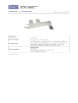
Upon installing the certificate or accepting the unrecognized
certificate for the current session, the browser login dialog box
appears.
3. Provide a valid Username and Password (set by the KVM
switchs administrator), and click Login to bring up the OSD
Main Page.
Note: If you supply an invalid login, the authentication routine will
return an Invalid Username or Password message. If you see this
message, log in again being careful to enter the correct Username
and Password.
AP Windows Client Login
In some cases, the Administrator may not want the B064-Series
KVM Switches to be available via browser. The Windows AP Client
allows Windows systems users access to the KVM switch without
having to go through a browser.
The AP Windows Client can be found in the Download Section
of the OSD or on the CD that came with your B064-Series KVM
Switch. If you do not have access to the CD, and browser access
to the KVM switch has already been disabled, you will need to
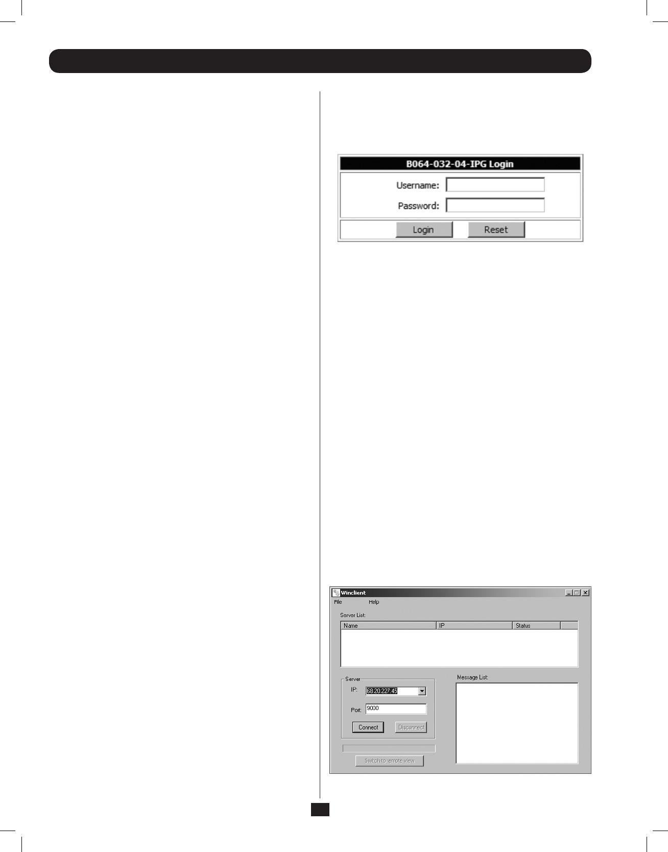
obtain the file from your system administrator. Once you have
saved the AP Windows Client, go to its location and double-click
the WinClient.exe icon to bring up the Windows Client Connection
Screen.
Note:
1. If you have trouble opening the AP Windows Client, save it to
your desktop and try again.
2. When accessing the AP Windows Client for the first time,
you will be prompted to provide a serial number. This serial
number can be found on the CD that came with your KVM.
201107009 93-2913.indd 6 7/18/2011 2:58:02 PM
7
Logging Into the B064-Series KVM Switch continued
AP Java Client Login
AP Windows Client Login continued
In those cases in which the Administrator does not want the B064-Series KVM Switch to be available via browser and the remote user is
not running Windows, the AP Java Client provides access to the KVM switch.
After downloading the AP Java Client, go to the location on your hard disk where you downloaded the program and double-click on it
to bring up the connection screen. The AP Java Client connection screen is the same as the Windows version, except that it does not
contain a menu bar with File and Help menus. Note: When accessing the AP Java Client for the first time, you will be prompted to
provide a serial number. This serial number can be found on the CD that came with your KVM.
The Connection Screen
A description of the contents of the Connection Screen is given in the following table:
Item Description
Menu Bar The Menu Bar contains two menus; File and Help. The File Menu allows the operator to Create, Save, and Open Work files.
Server List
Each time the WinClient.exe file is run, it searches the User’s LAN segment for B064-Series KVM Switches, and lists the ones it finds in
this box. Double-click on any of the units in this list to connect to it.
Note: For a switch to show up in the Server List, the Enable Device List check box in the Operating Mode page (see Operating Mode
section under Device Management in OSD Operation for details) must be checked and the Program service port in the Network page
(see Network section under Device Management in OSD Operation for details) must be set to the same number as in the AP Windows
Client Port field.
Server
This area is used when you want to connect to a B064-Series KVM Switch at a remote location.
• Click on the IP drop-down and select an address from the list. If the address you want is not listed, key in the target IP
address in the IP field, and its port number in the Port field.
• When the IP address and port number have been specied, click Connect to bring up a login dialog box. Provide a
Username and Password as provided by your system administrator and click OK to establish a connection with the B064-
Series KVM Switch.
• When you have nished with your session, click Disconnect to end the connection.
Message List Lists status messages regarding the connection to the B064-Series KVM Switch.
Switch to
Remote View
Once a remote connection with a B064-Series KVM Switch has been established, this button becomes active. Click it to switch to the
KVM Switch’s Main OSD Page.
The File Menu
The File Menu allows the operator to Create, Save, and Open Work Files. A Work File consists of all the information specified in a Client
session. This includes the items in the Server List and Server IP List.
Whenever a user runs the Client program, it opens with the values contained in the current Work File, i.e. the values that were in effect
when the program was last closed.
The File menu consists of three items:
Item Description
New Allows the user to create a named work file so that its values will not be lost and will be available for future use
Open Allows the user to open a previously saved work file and use the values contained in it
Save Allows the user to save the values presently in effect as the current work file
Exit Exits the AP Windows Client
1. If your KVM is displayed in the Server List, connect to it by highlighting it
and clicking on the Connect button. Note: For a switch to show up in the
Server List, the Enable Device List checkbox in the Operating Mode page (see
Operating Mode section under Device Management in OSD Operation for details
for details) must be checked and the Program server port must match what is
set in the Network page (See Network section under Device Management in
OSD Operation for details.)
2. If your KVM does not display in the Server List, enter in its IP address in the IP
server field and click the Connect button.
3. Upon clicking the connect button, you will be prompted to enter your username
and password. Enter in your username and password and press OK.
4. When connected, the Remote View button will be activated. Click on it to access
the KVM remotely. Click on the Disconnect button to log out of the KVM switch.
201107009 93-2913.indd 7 7/18/2011 2:58:02 PM
8
4. Warranty Registration
Visit www.tripplite.com/warranty today to register the warranty for your new Tripp Lite product. You’ll be automatically entered into a drawing for a chance to win a FREE Tripp Lite
product!*
* No purchase necessary. Void where prohibited. Some restrictions apply. See website for details.
3-Year Limited Warranty
TRIPP LITE warrants its products to be free from defects in materials and workmanship for a period of three (3) years from the date of initial purchase. TRIPP LITE’s obligation
under this warranty is limited to repairing or replacing (at its sole option) any such defective products. To obtain service under this warranty, you must obtain a Returned Material
Authorization (RMA) number from TRIPP LITE or an authorized TRIPP LITE service center. Products must be returned toTRIPP LITE or an authorized TRIPP LITE service center with
transportation charges prepaid and must be accompanied by a brief description of the problem encountered and proof of date and place of purchase. This warranty does not
apply to equipment which has been damaged by accident, negligence or misapplication or has been altered or modified in any way.
EXCEPT AS PROVIDED HEREIN, TRIPP LITE MAKES NO WARRANTIES, EXPRESS OR IMPLIED, INCLUDING WARRANTIES OF MERCHANTABILITY AND FITNESS FOR A PARTICULAR
PURPOSE. Some states do not permit limitation or exclusion of implied warranties; therefore, the aforesaid limitation(s) or exclusion(s) may not apply to the purchaser.
EXCEPT AS PROVIDED ABOVE, IN NO EVENT WILL TRIPP LITE BE LIABLE FOR DIRECT, INDIRECT, SPECIAL, INCIDENTAL OR CONSEQUENTIAL DAMAGES ARISING OUT OF THE
USE OF THIS PRODUCT, EVEN IF ADVISED OF THE POSSIBILITY OF SUCH DAMAGE. Specifically, TRIPP LITE is not liable for any costs, such as lost profits or revenue, loss of
equipment, loss of use of equipment, loss of software, loss of data, costs of substitutes, claims by third parties, or otherwise.
1111 W. 35th Street, Chicago, IL 60609 USA
www.tripplite.com/support
201107009 93-2913-EN
201107009 93-2913.indd 8 7/18/2011 2:58:02 PM
  • Page 1 1
  • Page 2 2
  • Page 3 3
  • Page 4 4
  • Page 5 5
  • Page 6 6
  • Page 7 7
  • Page 8 8

Tripp Lite B064-016-02-IPG User manual

Category
Networking
Type
User manual

Ask a question and I''ll find the answer in the document

Finding information in a document is now easier with AI