Kohler K-1122-HL-96 Installation guide

Category
Space heaters
Type
Installation guide
Important Information
WARNING: When using electrical products, basic precautions should always be followed, including
the following:
Building materials and wiring should be routed away from the pump body and other heat-producing
components of the unit.
Install to permit access for servicing.
Grounding is required. The unit should be installed by a qualified service representative, and grounded.
WARNING: Risk of electric shock. A licensed electrician should make all electrical connections.
WARNING: Risk of electric shock. Disconnect power before servicing.
WARNING: Risk of injury or property damage. Please read all instructions thoroughly before
beginning installation, including the following requirements.
NOTICE: Follow all local plumbing and electrical codes.
Product Information
Electrical Requirements
The installation must have a Class A Ground-Fault Circuit-Interrupter (GFCI). The GFCI protects against
line-to-ground shock hazard. Use a 120 V, 15 A, 60 Hz dedicated service for the whirlpool.
H models require a separate 120 V, 15 A, 60 Hz dedicated service for the heater.
NOTE: If the pump supply cord is damaged, it must be replaced by the manufacturer, its service agent or
similarly qualified persons in order to avoid a hazard. The heater supply cord cannot be replaced. If the
cord is damaged the heater should be scrapped.
Product Notices
WARNING: Unauthorized modification may cause unsafe operation and poor performance of the
whirlpool. Do not relocate the whirlpool pump, or make other modifications to the whirlpool system,
as this could adversely affect the performance and safe operation of the whirlpool. Kohler Co. shall not
be liable under its warranty or otherwise for personal injury or damage caused by any such
unauthorized modification.
WARNING: Risk of electrical shock. Disconnect power before servicing.
WARNING: Risk of electrical shock. A licensed electrician should make all electrical connections.
WARNING: Risk of injury or property damage. Please read all instructions thoroughly before
beginning installation.
NOTICE: Follow all local plumbing and electrical codes.
Factory-Assembled Features
Factory installed components include pump with power supply cord and air switch transmitter. No
installation is needed.
H models are also supplied with a factory assembled heater.
An optional timer kit is available for certain models.
The whirlpool pump and piping are factory-assembled.
Connections and Service Access
1012295-2-E 2 Kohler Co.
Important Information (cont.)
Before installation, ensure proper access to the final connections.
NOTICE: Provide unrestricted service access to the pump. You must provide access for servicing the
pump and controls. The access must be located immediately next to the pump. Study the roughing-in
information packed with the whirlpool.
Table of Contents
Important Information .............................................................. 2
Thank You For Choosing Kohler Company .............................................. 4
Tools and Materials ............................................................... 4
Before You Begin ................................................................. 4
Prepare the Site ................................................................. 5
Prepare the Whirlpool ............................................................. 5
Secure the Unit .................................................................. 6
Secure the Whirlpool to the Stud Framing ............................................... 7
Cut the Pump Banding Straps ....................................................... 7
Install the Plumbing ............................................................... 7
Make Electrical Connections ......................................................... 8
Test Run the Whirlpool ............................................................. 8
Complete the Finished Wall ........................................................ 10
Removing the Apron .............................................................. 10
Clean-Up After Installation ......................................................... 10
Confirm Proper Operation .......................................................... 11
Troubleshooting Procedure ......................................................... 12
Kohler Co. 3 1012295-2-E
Thank You For Choosing Kohler Company
We appreciate your commitment to Kohler quality. Please take a few minutes to review this manual before
you start installation. If you encounter any installation or performance problems, please don’t hesitate to
contact us. Our phone numbers and website are listed on the back cover. Thanks again for choosing Kohler
Company.
Tools and Materials
Before You Begin
CAUTION: Risk of product damage. Do not lift the whirlpool by the piping or pump, or use the
piping or pump for structural support of the whirlpool.
We recommend this whirlpool for alcove installation.
Inspect the whirlpool for damage before you begin installation.
You must install this whirlpool to an adequately supported, level subfloor.
Confirm adequate mounting and connection space for the faucet specified for your installation.
Kohler Co. reserves the right to make revisions in the design of products without notice, as specified
in the Price Book.
Sealant
Pencil
Level
Pipe Wrench
Drill
Tin Snips
• Conventional woodworking tools
and materials
• Drop cloth
• #6 large-head galvanized nails
• 2x4's
• Screws or lag bolts
• Construction Adhesive (optional)
• Cement or mortar (optional)
Plus:
Tape
Measure
Safety
Glasses
1012295-2-E 4 Kohler Co.
1. Prepare the Site
NOTICE: Unless otherwise specified, floor support under the whirlpool must provide for a minimum of
80 lbs/square foot (390 kg/square meter) loading.
NOTICE: Do not support the whirlpool by the rim.
Make sure the flooring offers adequate support for your whirlpool, and verify that the subfloor is
flat and level.
The whirlpool should be installed in an alcove installation. Construct 2x4 or 2x6 stud framing
designed for your particular installation. Construct a frame in accordance with the roughing-in
information packed with the whirlpool.
Position the plumbing according to the roughing-in information packed. Cap the supplies, and
check for leaks.
2. Prepare the Whirlpool
Install the drain to the whirlpool according to the drain manufacturer’s instructions. Do not connect
the trap at this time.
Position a clean drop cloth or similar material in the bottom of the whirlpool. Be careful not to
scratch the surface of the whirlpool.
Construct 2x4 or
2x6 stud framing
according to the
roughing-in
information.
Position the
rough plumbing.
Verify that the subfloor
offers adequate support,
and is flat and level.
Kohler Co. 5 1012295-2-E
3. Secure the Unit
CAUTION: Risk of product damage. Do not lift the whirlpool by the piping or pump, or use the
piping or pump for structural support of the whirlpool.
CAUTION: Risk of product damage. Do not support the whirlpool by the rim.
Choose the installation option that best applies to your particular installation. Follow the
appropriate instructions.
If the subfloor is not level, shim the whirlpool support blocks as necessary.
Option Using a Cement or Mortar Bed
NOTE: Do not use gypsum cement or drywall compound for this application, as they will not provide an
acceptable, durable bond.
NOTE: The pump support bracket (when the pump banding straps are cut) and support blocks must
rest directly on the subfloor.
Spread a 2 (5.1 cm) thick layer of cement or mortar on the subfloor where the whirlpool will be set.
This will help secure, level, and support the unit. Clear all the material away from the pump
support bracket and support block locations.
Position a piece of plastic drop cloth material on top of the cement or mortar bed. With help,
carefully lift the whirlpool into place, and make sure the pump support bracket and support blocks
do not rest in the bed material.
Insert the drain tailpiece into the trap. Make sure the whirlpool is level and resting on all support
blocks.
Option Using Construction Adhesive
Apply a generous amount of high-quality construction adhesive to the bottom of the support blocks.
With help, carefully lift the whirlpool into position.
Insert the drain tailpiece into the trap. Make sure the whirlpool is level and resting on all support
blocks.
Clear space for pump.
Spread a 2" (5.1 cm) layer of
cement or mortar bed material.
Clear spaces for
support blocks.
Apply construction adhesive
to the support blocks.
1012295-2-E 6 Kohler Co.
4. Secure the Whirlpool to the Stud Framing
Drill a small pilot hole through the nailing-in flange at each stud. Add shims between the nailing-in
flange and the studs as needed to eliminate gaps.
Nail 1/4 (6 mm) thick furring strips to the studs to shim out to the edge of the nailing-in flange.
Use #6 large-head galvanized nails to secure the nailing-in flange to the studs.
5. Cut the Pump Banding Straps
IMPORTANT! This step is necessary to make your Kohler whirlpool operate more quietly.
Use tin snips to cut the two pump banding straps.
To minimize whirlpool noise and vibration, be sure the pump is not in direct contact with the
shipping bracket after the pump banding straps are cut.
Remove and discard the straps.
6. Install the Plumbing
CAUTION: Risk of property damage. Ensure a watertight seal on the whirlpool drain.
Connect the drain to the trap according to the drain manufacturer’s instructions.
Install the faucet valving according to the faucet manufacturer’s instructions. Do not install the
faucet trim until instructed. Open the hot and cold water supplies, and check the supply
connections for leakage.
Run water into the whirlpool, and check the drain connections for leakage.
Stud
Nail 1/4" (6 mm)
thick furring strips
to the studs.
Drill a small hole
through the nailing-in
flange at each stud.
Use #6 large-head
galvanized nails to secure
the nailing-in flange to the
studs.
Drainage
Suction Line
Pump
Cut the pump
banding straps.
NOTE:
Pump model illustrated may differ from your
actual product.
Kohler Co. 7 1012295-2-E
7. Make Electrical Connections
WARNING: Risk of electric shock. Make sure the power has been disconnected before performing the
following procedures.
WARNING: Risk of electric shock. To reduce the risk of electrical shock, connect the pump and in-line
heater (if heater option included) to properly grounded, grounding-type receptacles protected by
Ground-Fault Circuit-Interrupters (GFCI’s). Do not remove the plugs’ grounding pins. Do not use
grounding adapters.
NOTE: The whirlpool model number is printed on a label near the whirlpool pump. This label also
identifies the electrical rating of the whirlpool.
Pump Wiring
NOTE: The whirlpool model number is printed on a label near the whirlpool pump. This label also
identifies the electrical rating of the whirlpool.
Your Kohler whirlpool bath is equipped with a cord and plug. All wiring of the pump and control
has been completed at the factory. A licensed electrician must install a GFCI-protected, 120 V, 15 A,
grounded outlet. No other load should be on this circuit. Locate the outlet behind the whirlpool,
and within 24 (61 cm) of the pump.
Plug the pump into this outlet.
NOTE: Make sure the air actuator tubing is securely attached to the pump, and is not kinked or damaged.
If a K-1639 Timer Kit will be used, install it now according to the instructions packed.
In-line Heater Wiring
H Models: The heater is equipped with a cord and plug. All wiring of the heater has been
completed at the factory. A licensed electrician must install a GFCI-protected, 120 V, 15 A, grounded
outlet. No other load should be on this circuit. Locate the outlet behind the whirlpool, and within
24 (61 cm) of the heater.
Plug the heater into this outlet.
8. Test Run the Whirlpool
Check all electrical connections, and make sure the electrical power to the whirlpool and heater (if
equipped) is on.
Make sure all union connections to the pump and heater are securely hand tightened.
Verify that the pump banding straps have been cut (if applicable), and that the pump is resting
directly on the subfloor or whirlpool base.
Bond in accordance
with applicable codes.
Install a GFCI-
protected 120 V, 15 A
grounded outlet.
Heater
Plug the pump
into this outlet.
Install second GFCI-
protected outlet for "H"
models for the in-line heater.
1012295-2-E 8 Kohler Co.
Test Run the Whirlpool (cont.)
Fill the whirlpool to a level at least 2 (5.1 cm) above the top of the highest jet.
Operate the whirlpool for 5 minutes, and check all whirlpool piping connections for leaks.
For additional information on whirlpool operation, refer to Confirm Proper Operation.
Kohler Co. 9 1012295-2-E
9. Complete the Finished Wall
NOTE: If your whirlpool has an integral apron, it is designed so the finished wall material (1-1/2 [3.8 cm]
maximum) will overlap the apron columns. The finished floor material (2 [5.1 cm] maximum) should butt
against the apron.
If you have not already done so, carefully remove the protective tape from the whirlpool rim.
If necessary allow for deck-mounted valves and spout.
Cover the framing with water-resistant wall material. Seal the joints between the whirlpool rim edge
and the water-resistant wall material with silicone sealant.
Tape and mud the water-resistant wall material. Install the finished wall to the water-resistant wall
material. Seal the joints between the whirlpool rim and the finished wall material with silicone
sealant.
Install the faucet trim according to the trim manufacturer’s instructions.
10. Removing the Apron
Your whirlpool may be equipped with an integral apron which allows you convenient access to
your whirlpool controls. To remove the apron, insert the edge of a flat blade screwdriver or dull
knife under the edge of the apron panel. Be careful not to scratch the visible surfaces. Gently pry up
at one end. Carefully pull the apron panel off.
To reinstall, bow the apron slightly so both ends can be inserted at the same time. Gently press in
the center of the panel to secure the apron in place.
11. Clean-Up After Installation
When cleaning up after installation, do not use abrasive cleansers, as they may scratch and dull the
whirlpool surface. Use warm water and a liquid detergent to clean the surface.
Remove stubborn stains, paint, or tar with turpentine or paint thinner. Do not allow cleaners
containing petroleum distillates to remain in contact with any whirlpool surfaces for long periods
of time. Remove plaster by carefully scraping with a wood edge. Do not use metal scrapers, wire
brushes, or other metal tools. Use a powder-type detergent on a damp cloth to provide mild
abrasive action to any residual plaster.
Framing
Whirlpool
Finished Wall
Water-Resistant
Wall Material
Apply silicone sealant to the
joint between the whirlpool
and the finished wall.
On models with an integral apron,
access the pump by gently prying
at the apron edge with a
screwdriver or dull knife to remove.
1012295-2-E 10 Kohler Co.
12. Confirm Proper Operation
Fill the Whirlpool
NOTE: Please read these steps carefully before you operate your whirlpool.
Position the jet nozzles so they face down toward the basin. Turn the jet trim rings fully
counterclockwise.
Fill the whirlpool to a water level at least 2 (5.1 cm) above the top of the highest jet.
NOTE: The water temperature in the whirlpool should not exceed 104°F (40°C).
To service orifices insert a pencil into the end of the jet nozzle and push the orifice out. After
removing any blockage, check the orifice to make sure it is clear and press it into the jet housing.
NOTE: Orifices are only installed in whirlpool jets when there are six or more jets in the whirlpool system.
Operating Sequence
Press the air actuator to turn on the whirlpool jets.
Adjust each jet for optimum air/water mixture. Turn the trim ring clockwise to reduce the air flow,
and counterclockwise to increase the air flow.
If equipped with a heater, the heater will engage automatically when the pump is turned on and
will disengage when the pump is turned off. The heater will not turn on if the water temperature
exceeds 104°F (40°C).
Press the air actuator a second time to turn off the whirlpool.
Fill with water at least 2" (5.1 cm)
above the highest jet.
Turn the jet trim ring
clockwise to
decrease the flow.
Position the jet
nozzles to direct
the water flow as
desired.
Turn the jet trim ring counterclockwise
to increase the flow.
Press the air actuator to turn
on and off the whirlpool.
Kohler Co. 11 1012295-2-E
13. Troubleshooting Procedure
Remove the Factory Installed Jets
NOTE: A special tool is provided with the replacement jets that will allow you to remove the jets from the
whirlpool. This tool is also supplied with each trim kit.
Position the jet ball nozzle so it is pointing upward.
NOTE: The nozzle must remain pointed up or the tool will slip off.
Insert the removal tool, hooked end up, into the opening of the jet and hook the inside top of the
nozzle.
Grasp the tool firmly and place your thumb against the whirlpool wall. Pull steadily on the tool
until the jet assembly pulls free of the hole. Be careful not to lose the O-ring.
Reinstall the Jets
NOTE: The jet O-ring must be correctly positioned, must be lubricated, and must be in good condition to
permit easy rotation and proper operation of the jet.
Install the O-ring onto the first shoulder of the jet. Lubricate the O-ring with silicone lubricant to
prevent noisy operation of the jet.
Carefully insert the jet into the housing, and lightly push and rotate the jet until it snaps into
position. Do not force the jet.
NOTE: When installed correctly, the jet should turn smoothly both clockwise and counterclockwise.
Troubleshooting Guide
This troubleshooting guide is for general aid only. A Kohler Authorized Service Representative or qualified
electrician should correct any electrical problems. For warranty service, contact your dealer or wholesale
distributor.
Symptoms Probable Causes Recommended Action
1. Whirlpool does not start
or stop.
A. No power to motor. A. Set/reset the GFCI or ELCB;
check wiring.
B. Air actuator does not work. B. Replace air actuator.
C. Air actuator tubing is
disconnected, loose, kinked,
plugged, or damaged.
C. Connect, straighten, clean, or
replace air actuator tubing.
D. Motor/pump does not work. D. Rebuild or replace motor/pump.
2. Motor starts, not all jets
are functioning.
A. Jet is closed. A. Rotate jet trim ring
counterclockwise to open.
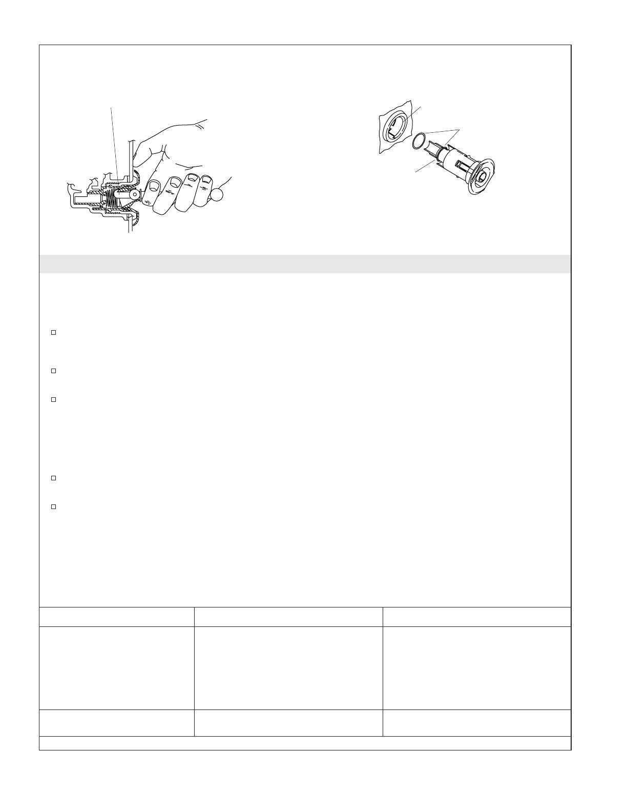
Remove the Jets
Insert the tool hook as shown and pull the jet out of the
housing. The jet should be facing up when this is done.
Housing
Reinstall the Jets
Insert the jet into the housing, and lightly
push and rotate until it snaps in position.
Slide the O-ring
onto the first
shoulder of the jet.
Inspect and
lubricate the O-ring.
1012295-2-E 12 Kohler Co.
Troubleshooting Procedure (cont.)
Symptoms Probable Causes Recommended Action
B. Jets are blocked. B. Remove blockage.
3. Whirlpool stops
automatically before 18
minutes.
A. The GFCI or ELCB trips. A. Identify source of fault, and
correct.
B. Suction blocked. B. Remove obstruction.
C. Jets are blocked. C. Remove blockage.
D. Motor overheated and protection
device activated.
D. Check for blockage at motor
vents. Remove blockage and
allow motor to cool.
Check for suction blockage.
Remove blockage and allow
motor to cool.
Check for jet blockage. Remove
blockage and allow motor to
cool.
4. Noisy operation. A. Pump banding straps have not
been cut. (Models with support
blocks only.)
A. Cut pump banding straps with
tin snips.
5. Heater does not operate.
(“H” models only)
A. No power to heater. A. Reset the GFCI or ELCB.
B. Water temperature exceeds 104° F
(40° C).
B. Allow water to cool and heater
will reengage.
C. Heater does not work. C. Replace heater.
Kohler Co. 13 1012295-2-E
  • Page 1 1
  • Page 2 2
  • Page 3 3
  • Page 4 4
  • Page 5 5
  • Page 6 6
  • Page 7 7
  • Page 8 8
  • Page 9 9
  • Page 10 10
  • Page 11 11
  • Page 12 12
  • Page 13 13
  • Page 14 14
  • Page 15 15
  • Page 16 16
  • Page 17 17
  • Page 18 18
  • Page 19 19
  • Page 20 20
  • Page 21 21
  • Page 22 22
  • Page 23 23
  • Page 24 24
  • Page 25 25
  • Page 26 26
  • Page 27 27
  • Page 28 28
  • Page 29 29
  • Page 30 30
  • Page 31 31
  • Page 32 32
  • Page 33 33
  • Page 34 34
  • Page 35 35
  • Page 36 36
  • Page 37 37
  • Page 38 38
  • Page 39 39
  • Page 40 40

Kohler K-1122-HL-96 Installation guide

Category
Space heaters
Type
Installation guide

Ask a question and I''ll find the answer in the document

Finding information in a document is now easier with AI