
GB Plunge Cut Circular Saw Instruction manual
F Scie circulaire plongeante Manuel d’instructions
D Tauchsäge Betriebsanleitung
I Sega circolare ad immersione Istruzioni per l’uso
NL Invalcirkelzaag Gebruiksaanwijzing
E Sierra de incisión Manual de instrucciones
P Serra Circular de Corte a Fundo Manual de instruções
DK Rundsav til indstikssnit Brugsanvisning
GR
Δισκοπρίονο βαθ ιάς κοπής Οδηγίες χρήσης
SP6000
Page is loading ...
Page is loading ...
Page is loading ...
Page is loading ...
Page is loading ...

7
ENGLISH
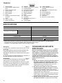
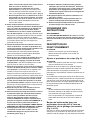
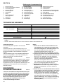
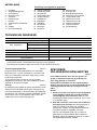
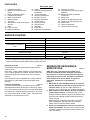
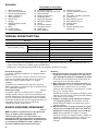
Explanation of general view
SPECIFICATIONS
• Due to our continuing programme of research and development, the specifications herein are subject to change without
notice.
• Note: Specifications may differ from country to country.
Intended use
ENE067-1
The tool is specially intended for performing plunge cuts.
In addition, lengthways and crossways straight cuts and
mitre cuts with angles in wood can also be performed
while in firm contact with the workpiece.
If the tool is equipped with the special saw blade for
aluminium, the tool can be used for sawing aluminium.
Power supply
ENF002-1
The tool should be connected only to a power supply of
the same voltage as indicated on the nameplate, and can
only be operated on single-phase AC supply. They are
double-insulated in accordance with European Standard
and can, therefore, also be used from sockets without
earth wire.
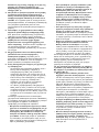
SPECIFIC SAFETY RULES GEB031-1
DO NOT let comfort or familiarity with product (gained
from repeated use) replace strict adherence to
circular saw safety rules. If you use this tool unsafely
or incorrectly, you can suffer serious personal injury.
Danger:
1. Keep hands away from cutting area and the blade.
Keep your second hand on auxiliary handle, or
motor housing. If both hands are holding the saw,
they cannot be cut by the blade.
2. Do not reach underneath the workpiece or tool
base. The guard cannot protect you from the blade
below the workpiece. Do not attempt to remove cut
material when blade is moving.
CAUTION: Blades coast after turn off. Wait until blade
stops before grasping cut material.
3. Adjust the cutting depth to the thickness of the
workpiece. Less than a full tooth of the blade teeth
should be visible below the workpiece.
4. Never hold piece being cut in your hands or
across your leg. Secure the workpiece to stable
platform. It is important to support the work properly
to minimize body exposure, blade binding, or loss of
control.
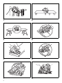
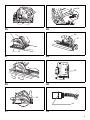
A typical illustration of proper hand support,
workpiece support, and supply cord routing (if
applicable). (Fig. 1)
1. Clamping screw
2. Blade lower limit stopper
3. Quick stop button
4. Clamping screws
5. Tool base
6. Positive stopper
7. Lever
8. Bevel angle shifting lever
9. Base
10. Cutting line
11. Lock-off button
12. Switch trigger
13. Speed adjusting dial
14. Hex wrench
15. Locking lever
16. Shaft lock
17. Hex bolt
18. Outer flange
19. Saw blade
20. Inner flange
21. Vacuum cleaner
22. Dust port
23. Adjusting screws
24. Slide lever
25. Rip fence (Guide rule)
26. Rear edge of tool base
27. Fixed stop
28. Adjusting screw for 90°
29. Adjusting screw for 45°
30. Limit mark
31. Screwdriver
32. Brush holder cap
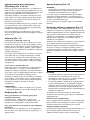
Model SP6000
Blade diameter 165 mm
Max. cutting depth
at 90° 56 mm
at 45° 40 mm
at 48° 38 mm
No load speed (min
-1
) 2,000 - 5,200
Overall length 341 mm
Net weight 4.1 kg
Safety class /II

8
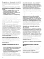
5. Hold power tool by insulated gripping surfaces
when performing an operation where the cutting
tool may contact hidden wiring or its own cord.
Contact with a “live” wire will also make exposed metal
parts of the power tool “live” and shock the operator.
6. When ripping always use a rip fence or straight
edge guide. This improves the accuracy cut and
reduces the chance of blade binding.
7. Always use blades with correct size and shape
(diamond versus round) of arbour holes. Blades
that do not match the mounting hardware of the saw
will run eccentrically, causing loss of control.
8. Never use damaged or incorrect blade washers or
bolt. The blade washers and bolt were specially
designed for your saw, for optimum performance and
safety of operation.
9. Causes and Operator Prevention of Kickback:
- kickback is a sudden reaction to a pinched, bound
or misaligned saw blade, causing an uncontrolled
saw to lift up and out of the workpiece toward the
operator;
- when the blade is pinched or bound tightly by the
kerf closing down, the blade stalls and the motor
reaction drives the unit rapidly back toward the
operator;
- if the blade becomes twisted or misaligned in the
cut, the teeth at the back edge of the blade can dig
into the top surface of the wood causing the blade
to climb out of the kerf and jump back toward the
operator.
Kickback is the result of saw misuse and/or incorrect
operating procedures or conditions and can be
avoided by taking proper precautions as given below.
• Maintain a firm grip with both hands on the saw
and position your arms to resist kickback
forces. Position your body to either side of the
blade, but not in line with the blade. Kickback
could cause the saw to jump backwards, but
kickback forces can be controlled by the operator, if
proper precautions are taken.
• When blade is binding, or when interrupting a
cut for any reason, release the trigger and hold
the saw motionless in the material until the
blade comes to a complete stop. Never attempt
to remove the saw from the work or pull the saw
backward while the blade is in motion or
kickback may occur. Investigate and take
corrective actions to eliminate the cause of blade
binding.
• When restarting a saw in the workpiece, centre
the saw blade in the kerf and check that saw
teeth are not engaged into the material. If saw
blade is binding, it may walk up or kickback from
the workpiece as the saw is restarted.
• Support large panels to minimise the risk of
blade pinching and kickback. Large panels tend
to sag under their own weight. Supports must be
placed under the panel on both sides, near the line
of cut and near the edge of the panel.
To minimize the risk of blade pinching and kickback.
When cutting operation requires the resting of the saw
on the workpiece, the saw should be rested on the
larger portion and the smaller piece cut off.
To avoid kickback, do support board or panel near
the cut. (Fig. 2)
Do not support board or panel away from the cut.
(Fig. 3)
• Do not use dull or damaged blades.
Unsharpened or improperly set blades produce
narrow kerf causing excessive friction, blade
binding and kickback. Keep blade sharp and clean.
Gum and wood pitch hardened on blades slows
saw and increases potential for kickback. Keep
blade clean by first removing it from tool, then
cleaning it with gum and pitch remover, hot water or
kerosene. Never use gasoline.
• Blade depth and bevel adjusting locking levers
must be tight and secure before making cut. If
blade adjustment shifts while cutting, it may cause
binding and kickback.
• Use extra caution when making a “plunge cut”
into existing walls or other blind areas. The
protruding blade may cut objects that can cause
kickback.
• ALWAYS hold the tool firmly with both hands.
NEVER place your hand, leg or any part of your
body under the tool base or behind the saw,
especially when making cross-cuts. If kickback
occurs, the saw could easily jump backwards over
your hand, leading to serious personal injury.
(Fig. 4)
• Never force the saw. Forcing the saw can cause
uneven cuts, loss of accuracy, and possible
kickback. Push the saw forward at a speed so that
the blade cuts without slowing.
10. Check guard for proper closing before each use.
Do not operate the saw if guard does not move
freely and enclose the blade instantly. Never
clamp or tie the guard with the blade exposed. If
saw is accidentally dropped, guard may be bent.
Check to make sure that guard moves freely and does
not touch the blade or any other part, in all angles and
depths of cut.
11. Check the operation and condition of the guard
return spring. If the guard and the spring are not
operating properly, they must be serviced before
use. Guard may operate sluggishly due to damaged
parts, gummy deposits, or a build-up of debris.
12. Assure that the guide plate of the saw will not shift
while performing the “plunge cut” when the blade
bevel setting is not at 90°. Blade shifting sideways
will cause binding and likely kick back.
13. Always observe that the guard is covering the
blade before placing saw down on bench or floor.
An unprotected, coasting blade will cause the saw to
walk backwards, cutting whatever is in its path. Be
aware of the time it takes for the blade to stop after
switch is released.
14. Use extra caution when cutting damp wood,
pressure treated lumber, or wood containing
knots. Adjust speed of cut to maintain smooth
advancement of tool without decrease in blade speed.

9
15. Avoid Cutting Nails. Inspect for and remove all
nails from lumber before cutting.
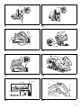
16. Place the wider portion of the saw base on that
part of the workpiece which is solidly supported,
not on the section that will fall off when the cut is
made. As examples, Fig. 5 illustrates the RIGHT
way to cut off the end of a board, and Fig. 6 the
WRONG way. If the workpiece is short or small,
clamp it down. DO NOT TRY TO HOLD SHORT
PIECES BY HAND!
17. Never attempt to saw with the circular saw held
upside down in a vise. This is extremely
dangerous and can lead to serious accidents.
(Fig. 7)
18. Some material contains chemicals which may be
toxic. Take caution to prevent dust inhalation and
skin contact. Follow material supplier safety data.
19. Do not stop the blades by lateral pressure on the
saw blade.
20. Always use blades recommended in this manual.
Do not use any abrasive wheels.
21. Wear a dust mask and hearing protection when
use the tool.
SAVE THESE INSTRUCTIONS.
WARNING:
MISUSE or failure to follow the safety rules stated in
this instruction manual may cause serious personal
injury.
FUNCTIONAL DESCRIPTION
CAUTION:
• Always be sure that the tool is switched off and
unplugged before adjusting or checking function on the
tool.
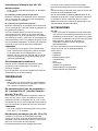
Adjusting depth of cut (Fig. 8)
CAUTION:
• After adjusting the depth of cut, always tighten the
clamping screw securely.
Loosen the clamping screw on the depth guide and move
the blade lower limit stopper to the desired depth on the
scale plate. At the desired depth of cut, tighten the
clamping screw firmly.
For cleaner, safer cuts, set cut depth so that no more than
one blade tooth projects below workpiece. Using proper
cut depth helps to reduce potential for dangerous
KICKBACKS which can cause personal injury.
NOTE:
• Setting the blade lower limit stopper to the desired
depth on the scale plate allows rough depth of cut.
For accurate depth of cut, measure the actual
protrusion of saw blade below the tool base.
Quick stop button for 2 to 3 mm depth of
cut when using guide rail (accessory)
(Fig. 9 & 10)
This tool has the quick stop button for 2 to 3 mm depth of
cut on the gear housing aside the rear handle when using
guide rail. This is used when avoiding splinter on the
workpiece in the cut. Make a pass of the 2 to 3 mm first
cut and then make another pass of usual cut.
To obtain the 2 to 3 mm depth of cut, push in the stop
button toward the saw blade. This is convenient for
avoiding splinter on the workpiece.
To release the depth of cut from this position for free depth
of cut, just pull the button back.
Bevel cutting (Fig. 11)
Tilting to the right (Fig. 12 & 13)
Turn the positive stopper so that the arrow on it points one
of two positions (vertical for 22.5°, horizontal for 45°).
Loosen the clamping screws in front and back. Then, tilt
the tool base until it stops and secure the base with the
clamping screws.
To get 48° bevel angle, move the lever to 48° marking as
far as it will go. Turn the positive stopper so that the arrow
on it points to the horizontal position. Then, tilt the tool
base until it stops and secure the base with the clamping
screws.
Tilting to the left (Fig. 14)
The tool can be tilted to the left 1° bevel angle. To get the
left 1° bevel angle, loosen the clamping screws in front
and back, tilt the tool handle slightly to the right and push
two bevel angle shifting levers at the same time in the
direction of arrow which has a marking -1. And then tilt the
tool handle to the left while pushing these two levers at
the same time. Secure the base with the clamping screws.
NOTE:
• Returning the blade to the right angle makes the
shifting lever return to 0° by itself.
Sighting (Fig. 15)
When using the tool without guide rail (accessory)
For straight cuts, align the A position on the front of the
base with your cutting line. For 45° bevel cuts, align the B
position with it.
When using the tool with guide rail (accessory)
For both straight cuts and 45° bevel cuts, always align the
A position on the front of the base with your cutting line.
Switch action (Fig. 16)
CAUTION:
• Before plugging in the tool, always check to see that
the switch trigger actuates properly and returns to the
“OFF” position when released.
To prevent the switch trigger from being accidentally
pulled, a lock-off button is provided. To start the tool, push
in the lock-off button and pull the switch trigger.
Release the switch trigger to stop.

10
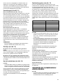
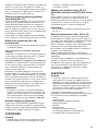
Speed adjusting dial (Fig. 17)
The tool speed can be infinitely adjusted between 2,000
and 5,200 rotations per minute by turning the adjusting
dial. Higher speed is obtained when the dial is turned in
the direction of number 6; lower speed is obtained when it
is turned in the direction of number 1.
Refer to the table to select the proper speed for the
workpiece to be cut. However, the appropriate speed may
differ with the type or thickness of the workpiece. In
general, higher speeds will allow you to cut workpieces
faster but the service life of the blade will be reduced.
CAUTION:
• The speed adjusting dial can be turned only as far as 6
and back to 1. Do not force it past 6 or 1, or the speed
adjusting function may no longer work.
• The speed adjusting dial is not for using low speed
rated saw blades but for obtaining a speed which is
suitable to material of workpiece. Use only saw blades
which are rated for at least 5,200 min
-1
.
The tools equipped with electronic function are easy to
operate because of the following features.
Overload protector
When the tool is overloaded and current flows above a
certain level, the tool automatically stops to protect motor.
Constant speed control
Electronic speed control for obtaining constant speed.
Possible to get fine finish, because the rotating speed is
kept constant even under load condition.
Soft start feature
Soft start because of suppressed starting shock.
ASSEMBLY
CAUTION:
• Always be sure that the tool is switched off and
unplugged before carrying out any work on the tool.
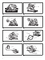
Hex wrench storage (Fig. 18)
Hex wrench is stored on the tool. To remove hex wrench,
just pull it out.
To install hex wrench, place it on the grip and insert it as
far as it will go.
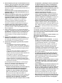
Removing or installing saw blade
CAUTION:
• Do not use saw blades which do not comply with the
characteristics specified in these instructions.
• Use only saw blades which are rated for at least
5,200 min
-1
.
• Be sure the blade is installed with teeth pointing up at
the front of the tool.
• Use only the Makita wrench to install or remove the
blade.
To remove the blade, push in the lock-off button to unlock
the upper limit stopper.
(Fig. 19)
Turn the locking lever to lock the saw head for replacing a
blade.
(Fig. 20)
With the lock-off button depressed and the locking lever
turned, lower the handle so that the lock pin fits in the
groove formed by the locking lever and the depth guide
with scale plate. Make sure that the lock pin fits in the
groove.
Press the shaft lock fully so that the blade cannot revolve
and use the wrench to loosen the hex bolt
counterclockwise. Then remove the hex bolt, outer flange
and blade.
(Fig. 21)
To install the blade, follow the removal procedure in
reverse. BE SURE TO TIGHTEN THE HEX BOLT
CLOCKWISE SECURELY.
(Fig. 22)
Connecting a vacuum cleaner (Fig. 23)
When you wish to perform clean cutting operation,
connect a Makita vacuum cleaner to your tool. Connect a
hose of the vacuum cleaner to the dust port as shown in
the figure.
OPERATION
Section cutting (ordinary sawing) (Fig. 24)
CAUTION:
• Be sure to move the tool forward in a straight line
gently. Forcing or twisting the tool will result in
overheating the motor and dangerous kickback,
possibly causing severe injury.
• Never approach any part of your body under the tool
base when section cutting, especially at starting. Doing
so may cause serious personal injuries. The blade is
exposed under the tool base.
Hold the tool firmly. The tool is provided with both a front
grip and rear handle. Use both to best grasp the tool. If
both hands are holding saw, they cannot be cut by the
blade. Set the front of base on the workpiece to be cut
without the blade making any contact. Then push in the
lock-off button and turn the tool on and wait until the blade
attains full speed. Now press down the saw head slowly to
the preset depth of cut and simply move the tool forward
over the workpiece surface, keeping it flat and advancing
smoothly until the sawing is completed.
To get clean cuts, keep your sawing line straight and your
speed of advance uniform. If the cut fails to properly follow
your intended cut line, do not attempt to turn or force the
tool back to the cut line. Doing so may bind the blade and
lead to dangerous kickback and possible serious injury.
Release switch, wait for blade to stop and then withdraw
tool. Realign tool on new cut line, and start cut again.
Attempt to avoid positioning which exposes operator to
chips and wood dust being ejected from saw. Use eye
protection to help avoid injury.
Number min
-1
12,000
22,200
33,100
44,000
54,900
65,200

11
When using with guide rail (accessory)
(Fig. 25 & 26)
Place the tool on the rear end of guide rail. Turn two
adjusting screws on the tool base so that the tool slides
smoothly without a clatter. Hold the tool firmly. The tool is
provided with both a front grip and rear handle. Use both
to best grasp the tool. Turn on the tool, press down the
tool to the preset depth of cut and cut the splinterguard
along the full length with a stroke. The edge of the
splinterguard corresponds to the cutting edge.
When bevel cutting with the guide rail, slide the slide lever
on the tool base so that the tool does not fall down on its
side.
Move the slide lever on the tool base in the direction of
arrow so that it engages the undercut groove in the guide
rail.
Rip fence (guide rule) (Accessory)
(Fig. 27)
The handy rip fence allows you to do extra-accurate
straight cuts. Simply slide the rip fence up snugly against
the side of the workpiece and secure it in position with the
screws on the front and the back of the base. It also
makes repeated cuts of uniform width possible.
Overturning the rip fence (guide rule) also works as a sub
base for the tool.
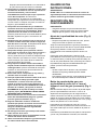
Plunge cutting (Cutting-out) (Fig. 28)
WARNING:
• To avoid a kickback, be sure to observe the following
instructions.
When using the tool without guide rail
Place the tool on the workpiece with the rear edge of tool
base against a fixed stop or equivalent which is devised
by an operator.
When using the tool with guide rail
Place the tool on the guide rail with the rear edge of tool
base against a fixed stop or equivalent which is clamped
on the guide rail.
Hold the tool firmly with one hand on the front grip and the
other on the tool handle. Then push in the lock-off button
and turn the tool on and wait until the blade attains full
speed. Now press down the saw head slowly to the preset
depth of cut and simply move the tool forward to the
desired plunge position.
NOTE:
• The markings on the side of the blade guard show the
absolute front and the absolute rear cutting points of
the saw blade (A for diameter 160 mm and B for
diameter 165 mm) at the maximum cutting depth and
using the guide rail.
(Fig. 29)
Guide device (accessories)
Use of the miter gauge (accessory) allows exact miter
cuts with angles and fitting works.
Use of the clamp (accessory) ensures firm hold of
workpiece on the table.
MAINTENANCE
CAUTION:
• Always be sure that the tool is switched off and
unplugged before attempting to perform inspection or
maintenance.
Adjusting for accuracy of 90° and 45° cut
(vertical and 45° cut) (Fig. 30 & 31)
This adjustment has been made at the factory. But if it is
off, adjust the adjusting screws with a hex wrench while
inspecting 90° or 45° the blade with the base using a
triangular rule or square rule, etc.
NOTE:
• Adjusting for accuracy of 22.5°, 48° and -1° cut cannot
be performed.
Replacing carbon brushes (Fig. 32 & 33)
Remove and check the carbon brushes regularly.
Replace when they wear down to the limit mark. Keep the
carbon brushes clean and free to slip in the holders.
Both carbon brushes should be replaced at the same
time. Use only identical carbon brushes.
Use a screwdriver to remove the brush holder caps.
Take out the worn carbon brushes, insert the new ones
and secure the brush holder caps.
To maintain product SAFETY and RELIABILITY, repairs,
any other maintenance or adjustment should be
performed by Makita Authorized Service Centers, always
using Makita replacement parts.
ACCESSORIES
CAUTION:
• These accessories or attachments are recommended
for use with your Makita tool specified in this manual.
The use of any other accessories or attachments might
present a risk of injury to persons. Only use accessory
or attachment for its stated purpose.
If you need any assistance for more details regarding
these accessories, ask your local Makita Service Center.
• Saw blades
•Guide rail
• Rip fence (Guide rule)
• Miter gauge
•Clamp
•Hex wrench
• Sheet set for guide rail
• Rubber sheet set for guide rail
• Position sheet set for guide rail
Page is loading ...
Page is loading ...
Page is loading ...
Page is loading ...
Page is loading ...
Page is loading ...
Page is loading ...
Page is loading ...
Page is loading ...
Page is loading ...
Page is loading ...
Page is loading ...
Page is loading ...
Page is loading ...
Page is loading ...
Page is loading ...
Page is loading ...
Page is loading ...
Page is loading ...
Page is loading ...
Page is loading ...
Page is loading ...
Page is loading ...
Page is loading ...
Page is loading ...
Page is loading ...
Page is loading ...
Page is loading ...
Page is loading ...
Page is loading ...
Page is loading ...
Page is loading ...
Page is loading ...
Page is loading ...
Page is loading ...
Page is loading ...
Page is loading ...
Page is loading ...
Page is loading ...
Page is loading ...
Page is loading ...
Page is loading ...
Page is loading ...
Page is loading ...
Page is loading ...
Page is loading ...
Page is loading ...
Page is loading ...

60
Tomoyasu Kato CE 2006
Director Amministratore
Directeur Directeur
Direktor Director
Responsible manufacturer: Produttore responsabile:
Fabricant responsable : Verantwoordelijke fabrikant:
Verantwortlicher Hersteller: Fabricante responsable:
Makita Corporation
3-11-8, Sumiyoshi-cho, Anjo, Aichi, JAPAN
Authorized Respresentative in Europe: Rappresentanti autorizzati in Europa:
Représentant agréé en Europe : Erkende vertegenwoordiger in Europa:
Autorisierte Vertretung in Europa: Representante autorizado en Europa:
Makita International Europe Ltd.
Michigan Drive, Tongwell, Milton Keynes,
Bucks MK15 8JD, ENGLAND
EC-DECLARATION OF CONFORMITY
We declare under our sole responsibility that this product is in
compliance with the following standards of standardized
documents;
EN60745, EN55014, EN61000 in accordance with Council
Directives, 2004/108/EC, 98/37/EC.
DÉCLARATION DE CONFORMITÉ CE
Nous déclarons, sous notre entière responsabilité, que ce
produit répond aux normes suivantes de documents
normalisés :
EN60745, EN55014, EN61000 conformément aux Directives
du Conseil, 2004/108/EC, 98/37/EC.
EG-KONFORMITÄTSERKLÄRUNG
Wir erklären unter unserer alleinigen Verantwortlichkeit, dass
sich dieses Produkt in Übereinstimmung mit den folgenden
Normen der Normdokumente
EN60745, EN55014, EN61000 befindet sowie in
Übereinstimmung mit den Ratsverordnungen 2004/108/EC,
98/37/EC.
DICHIARAZIONE DI CONFORMITÀ CE
Dichiariamo sotto nostra esclusiva responsabilità che il
presente prodotto è conforme alle seguenti norme o
documenti normativi:
EN60745, EN55014, EN61000 secondo le disposizioni delle
direttive del Consiglio, 2004/108/CE, 98/37/CE.
EU-VERKLARING VAN CONFORMITEIT
Wij verklaren onder eigen verantwoordelijkheid dat dit product
voldoet aan de normen in de volgende genormaliseerde
documenten:
EN60745, EN55014, EN61000 in overeenstemming met de
richtlijnen van de Raad, 2004/108/EC, 98/37/EC.
DECLARACIÓN DE CONFORMIDAD DE LA CE
Declaramos bajo nuestra exclusiva responsabilidad que este
producto cumple con los siguientes estándares de
documentos estandarizados;
EN60745, EN55014, EN61000 de acuerdo con las directivas
del Consejo, 2004/108/EC, 98/37/EC.
ENGLISH
FRANÇAIS
DEUTSCH
ITALIANO
NEDERLANDS
ESPAÑOL
Page is loading ...

62
Tomoyasu Kato CE 2006
Director Amministratore
Directeur Directeur
Direktor Director
Responsible manufacturer: Produttore responsabile:
Fabricant responsable : Verantwoordelijke fabrikant:
Verantwortlicher Hersteller: Fabricante responsable:
Makita Corporation
3-11-8, Sumiyoshi-cho, Anjo, Aichi, JAPAN
Authorized Respresentative in Europe: Rappresentanti autorizzati in Europa:
Représentant agréé en Europe : Erkende vertegenwoordiger in Europa:
Autorisierte Vertretung in Europa: Representante autorizado en Europa:
Makita International Europe Ltd.
Michigan Drive, Tongwell, Milton Keynes,
Bucks MK15 8JD, ENGLAND
For European countries only
Noise and Vibration
The typical A-weighted noise levels are
sound pressure level: 89 dB (A)
sound power level: 100 dB (A)
Uncertainty: 3 dB (A)
- Wear ear protection. -
The typical weighted root mean square acceleration value is
not more than 2.5 m/s
2
.
These values have been obtained according to EN60745.
Pour l'Europe uniquement
Bruit et vibrations
Les niveaux de bruit pondéré A typiques sont les suivants :
niveau de pression sonore = 89 dB (A)
niveau de puissance sonore = 100 dB (A)
Incertitude : 3 dB (A)
- Portez des protections auditives. -
La valeur d’accélération quadratique pondérée typique ne
dépasse pas 2,5 m/s
2
.
Ces valeurs ont été obtenues selon l’EN60745.
Nur für europäische Länder
Geräusche und Vibrationen
Die typischen effektiven Geräuschpegel betragen für
Schalldruck: 89 dB (A)
Schallleistungspegel: 100 dB (A)
Die Abweichung beträgt 3 dB (A)
- Tragen Sie Gehörschutz. -
Der typische effektive Beschleunigungswert beträgt höchstens
2,5 m/s
2
.
Diese Werte wurden entsprechend der Norm EN60745
gewonnen.
Solo per i paesi europei
Rumore e vibrazione
I tipici livelli di rumore ponderati "A" sono
livello di pressione sonora: 89 dB (A)
livello di potenza sonora: 100 dB (A)
Variazione: 3 dB (A)
- Indossare una protezione acustica. -
In genere, il valore efficace ponderato dell'accelerazione non
supera i 2,5 m/s
2
.
Questi valori sono stati ottenuti in conformità con la norma
EN60745.
Alleen voor Europese landen
Geluid en trillingen
De typischa, A-gewogen geluidsniveaus zijn
geluidsdrukniveau: 89 dB (A)
geluidsvermogenniveau: 100 dB (A)
Afwijking: 3 dB (A)
- Draag gehoorbescherming. -
De typisch, gewogen, kwadratisch-gemiddelde
versnellingswaarde is niet hoger dan 2,5 m/s
2
.
Deze waarden zijn verkregen volgens EN60745.
Sólo para los países europeos
Ruido y vibración
Los niveles típicos de ruido ponderado A son
nivel de presión sonora: 89 dB (A)
nivel de potencia sonora: 100 dB (A)
Incertidumbre: 3 dB (A)
- Utilice protección para los oídos. -
El valor ponderado de aceleración no es superior a 2,5 m/s
2
.
Estos valores se han obtenido conforme a EN60745.
ENGLISH
FRANÇAIS
DEUTSCH
ITALIANO
NEDERLANDS
ESPAÑOL
Page is loading ...

Makita Corporation
Anjo, Aichi, Japan
884683C999
-
 1
1
-
 2
2
-
 3
3
-
 4
4
-
 5
5
-
 6
6
-
 7
7
-
 8
8
-
 9
9
-
 10
10
-
 11
11
-
 12
12
-
 13
13
-
 14
14
-
 15
15
-
 16
16
-
 17
17
-
 18
18
-
 19
19
-
 20
20
-
 21
21
-
 22
22
-
 23
23
-
 24
24
-
 25
25
-
 26
26
-
 27
27
-
 28
28
-
 29
29
-
 30
30
-
 31
31
-
 32
32
-
 33
33
-
 34
34
-
 35
35
-
 36
36
-
 37
37
-
 38
38
-
 39
39
-
 40
40
-
 41
41
-
 42
42
-
 43
43
-
 44
44
-
 45
45
-
 46
46
-
 47
47
-
 48
48
-
 49
49
-
 50
50
-
 51
51
-
 52
52
-
 53
53
-
 54
54
-
 55
55
-
 56
56
-
 57
57
-
 58
58
-
 59
59
-
 60
60
-
 61
61
-
 62
62
-
 63
63
-
 64
64


Ask a question and I''ll find the answer in the document
Finding information in a document is now easier with AI
in other languages
- italiano: Makita SP 6000 Manuale utente
- français: Makita SP 6000 Manuel utilisateur
- español: Makita SP 6000 Manual de usuario
- Deutsch: Makita SP 6000 Benutzerhandbuch
- Nederlands: Makita SP 6000 Handleiding
- português: Makita SP 6000 Manual do usuário
- dansk: Makita SP 6000 Brugermanual