Page is loading ...

Introduction
Adding a RainSensor or RainSensor + Freeze
to your automatic sprinkler system is an
effective means of conserving water and
lowering your monthly water bill, while
promoting a healthier lawn and garden.
Designed for ease of installation, your sensor-
controlled irrigation system will be up and
running in minutes.
Prior to installing the RainSensor, take a few
moments to read through the instructions in
their entirety. Since the RainSensor is designed
to work with most makes and models of
automatic sprinkler timers, you should also refer
to the instructions provided with your timer for
specific information regarding the connection
and use of a rain sensor or rain switch.
Important:
The RainSensor is rated for 24 VAC power only. Connecting to a higher
voltage may result in severe equipment damage.
Installation methods must comply with all applicable national and local
electrical codes. If you are unsure about proper wiring practices, have a
qualified contractor perform the installation for you.
The RainSensor must not be submerged. Do not install the sensor inside a
rain gutter or any location where water can accumulate.
RainSensor Components
1 - Test Spindle - Pressed to manually test
RainSensor operation.
2 - Rainfall Adjustment Cap - Adjusts
RainSensor sensitivity from 3mm to 25mm
of detected rainfall.
3 - Quick-Clip
TM
- Universal mounting bracket
for easy installation.
4 - Connection Cable - 25ft (7.6m) of connec-
tion cable included.
5 - Access Cover - Easily removed for access
to internal components.
Wired RainSensor
TM
- Model 53769
RainSensor
TM
+ Freeze - Model 53853
Installation Guide
1
2
3
4
Figure 1
5

Installation Procedure
v Adjust Rain Sensitivity: The sensitivity setting determines the amount of
rainfall required to trigger the RainSensor and suspend automatic watering.
The RainSensor is factory-set at 6mm. Prior to installing the RainSensor, adjust
the rainfall sensitivity as preferred to one of four optional settings as indicated in
Figure 2.
To adjust, turn the cap slightly to disengage the pins
from the current setting. Adjust the cap up or down to
the preferred slot position, then re-engage the pins.
Note: Make sure the slot is correctly aligned with the pin
when making an adjustment. Do not force the cap into
position.
Note: The 3mm setting is not recommended for loca-
tions where high-humidity is common.
v Set Sensor Operation Mode (Applies to Model 53769, RainSensor Only):
The RainSensor is preset for normally-closed sensor operation, but can be
easily converted to normally-open if needed. Prior to installation, determine
whether your automatic timer requires a normally-closed or normally-open sen-
sor by referring to the timer user’s guide. If a normally-open sensor is required
(for example, when used with a Toro ECx
TM
or GreenKeeper
®
timer), configure
the RainSensor as shown in Figure 3.
Model 53853 only: If using the Freeze version, model 53853, and your
controller requires Normally Open Sensor operation, the sensor connection can
not be used. Instead, refer to the wiring configuration B and C under “Connect
RainSensor Wiring” section.
1. Using a small screwdriver, release and
remove the access cover by depressing
the two retaining tabs. Slide the control
board assembly out of the housing.
See Figure 3.
2. Carefully remove the wire connector from
the left pin of the microswitch and attach it
to the center pin. Leave the right wire
connected.
3. Slide the control board back into the
housing making sure it is properly aligned.
Install the access cover with the connection
wire knot on the inside the housing.
6mm
13mm
25mm
19mm
3mm
Figure 2
Normally Open
Normally Closed
Figure 3

v Select the Installation Site:
To operate properly, the RainSensor must be installed in an outdoor location
that provides the following conditions:
• As close to the timer as possible. If the connection wire will not reach the timer, it
can be extended to 100ft (30m) using 18 AWG (1.0mm
2
) insulated wire.
• Exposed to unobstructed sunlight and rainfall.
• Shielded from irrigation spray and rainwater runoff.
• Model 53853 only – Locate the RainSensor + Freeze model in the coolest por-
tion of the watered area. A northeast to northwest exposure is preferable. Avoid
installation near a heat source, such as a chimney or dryer vent.
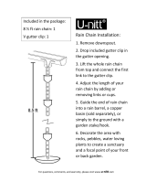
v Install the RainSensor
A rain gutter is an ideal location for the RainSensor. Simply position the bracket
with the thumbscrew under the top lip of the rain gutter and tighten to secure (do
not over-tighten). See Figure 4.
The RainSensor can also be mounted on any suitable solid structure such as
the side of the roof, a shed, or fence using the two supplied stainless steel
screws. See Figure 5 below.
Once securely fastened, adjust the RainSensor on the mounting bracket to align
the housing vertically.
Rain Gutter
Connection Wire
To Controller
Figure 4
Thumbscrew
Figure 5
Stainless Steel
Screws
Connection Wire
To Controller

v Connect RainSensor Wiring:
Route the RainSensor connection wire into the timer through the access hole in
the base of the timer cabinet.
Note: Avoid routing the wire over any sharp edges where damage to the wire
insulation may occur. For best results, hide the wire as much as possible by
tucking it under shingles and/or moldings. Seal any holes made by passing the
wire through structure walls.
Caution: To prevent severe equipment damage, never connect the
RainSensor to any power source greater than 24 VAC. If you are in doubt,
contact a qualified installer or electrician.
1. Disconnect power to the timer.
2. Use one of the following connection methods A, B or C, that best suits the
timer model configuration.
• Find the controller sensor terminals (generally marked “SENSOR”, “SEN”
or “S”) and attach the RainSensor control wires directly to these terminals
(in either order).
Note: There may be a jumper wire connecting the two Sensor wire terminals
that must be removed when connecting the RainSensor. Also, place the Sensor
Bypass switch in the Active position for sensor-controlled operation.
• Remove the valve common wire(s) from the valve common wire terminal and
join to one RainSensor wire lead using a twist-on wire connector. Attach the
remaining RainSensor wire lead to the valve common terminal.
Common Wire From Valves
Timer with Sensor terminals, with or without pump start/
master valve:
A
Sensor Bypass Switch
Common Wire From Valves
To Valves
Twist-on Wire Connector
Irrigation System Timer
Timer without Sensor terminals or pump start/ master
valve:
B
To Valves

• Remove all common wires from the common terminal(s) and join to one
RainSensor wire lead using a twist-on wire connector. (Be sure to include the
common wire from the pump start relay or master valve in this connection).
Attach the remaining RainSensor wire lead to the valve common terminal.
Testing the RainSensor Installation
To test the RainSensor operation, turn on a watering zone visible from the
RainSensor location. Press and hold down the Test Spindle; watering should
stop within a short time. If watering does not stop, recheck the wiring connec-
tions at the timer. If the timer has a Sensor Bypass switch, make sure the switch
is set to Active.
Note: The installation and operation of a freeze sensor should be used
in conjunction with frequent visual checks of your sprinkler system. While
freeze sensors are designed to prevent inadvertent watering during near
or below freezing conditions, there are instances in which manual interven-
tion is required. Air temperatures may be above freezing while ground and
vegetation temperatures remain below freezing. Operation of your sprinkler
system during these conditions may cause icing. Very rapid air tempera-
ture changes may also result in inadvertent watering, should the timing of
sprinkling coincide with rapid temperature changes. The Sensor should be
inspected for damage and manually tested regularly to ensure proper
operation.
Caution: Visual checks and prudent manual watering suspension
must be used in conjunction with any freeze sensor.
A freeze sensor should only be relied upon as an aid along with good
watering practices including frequent visual checks. This device is not
intended for farm/crop protection.
Common Wire From Valves
To Valves
Pump Start
Relay/Master
Valve
Irrigation System Timer
Timer without Sensor terminals, with pump start/master
valve:
C
Twist-on Wire Connector

RainSensor Operation
v Automatic Operation
When the RainSensor activates due to sufficient rainfall (or freezing conditions
- model 53853 only), watering will be terminated until the RainSensor automati-
cally resets. The reset rate will vary depending on temperature, solar radiation,
humidity and wind—the same conditions exposed to your landscape.
v Bypass Operation
To bypass RainSensor operation, place the timer’s sensor switch in the Bypass
position, or temporarily remove the RainSensor from the valve common wire cir-
cuit.
Model 53853 only: The freeze sensor is designed to terminate auto-
matic watering when air temperature reaches approximately 3°C (37°F)
+/- 2°C. Once freezing has occurred, the air temperature can increase
above the sensor trigger point, while the ground temperature remains at
or below freezing – resulting in icing conditions. Additionally, watering
can occur if the automatic watering schedule coincides with a very rapid
decrease in temperature.
Specifications
Mounting: Quick-Clip
TM
rain gutter bracket or screws (2 provided)
Connection Wire: 25ft (7.6m) –1.0mm
2
insulated 2-lead cable, UL-approved
Sensor Type: Industry-standard hygroscopic disc stack with adjustable
rainfall sensitivity
Switch Rating: 3A, 24 VAC, Normally Open/Normally Closed
Operating Temperature Range: -29°C to 60°C
Model 53853 Rain+Freeze only: Freeze set point of 3°C (37°F) +/- 2°C.
Material: Stainless steel and UV-resistant engineered polymer
The Toro Promise — Limited One-Year Warranty
The Toro Company and its affiliate, Toro Warranty Company, pursuant to an agreement between
them, jointly warrants, to the owner against defects in material and workmanship for a period of one
year from the date of purchase.
Neither The Toro Company nor Toro Warranty Company is liable for failure of products not manu-
factured by them even though such products may be sold or used in conjunction with Toro products.
During such warranty period, we will repair or replace, at our option, any part found to be defective.
Return the defective part to the place of purchase.
Our liability is limited solely to the replacement or repair of defective parts. There are no other
express warranties.
This warranty does not apply where equipment is used, or installation is performed, in any manner
contrary to Toro’s specifications and instructions, nor where equipment is altered or modified.
NEITHER THE TORO COMPANY NOR TORO WARRANTY COMPANY IS LIABLE FOR INDI-
RECT, INCIDENTAL OR CONSEQUENTIAL DAMAGES IN CONNECTION WITH THE USE OF
EQUIPMENT, INCLUDING BUT NOT LIMITED TO: VEGETATION LOSS, THE COST OF SUB-
STITUTE EQUIPMENT OR SERVICES REQUIRED DURING PERIODS OF MALFUNCTION OR
RESULTING NON-USE, PROPERTY DAMAGE OR PERSONAL INJURY RESULTING FROM
INSTALLER’S NEGLIGENCE.
Some states do not allow the exclusion or limitation of incidental or consequential damages, so the
above limitation or exclusion may not apply to you.
ALL IMPLIED WARRANTIES, INCLUDING THOSE OF MERCHANTABILITY AND FITNESS FOR
USE, ARE LIMITED TO THE DURATION OF THIS EXPRESS WARRANTY.
Some states do not allow limitations of how long an implied warranty lasts, so the above limitation
may not apply to you.
This warranty gives you specific legal rights and you may have other rights which vary from state to
state.
© 2009 The Toro Company • www.toro.com • 1-800-367-8676 373-0542 Rev. B
/