
WHITE-RODGERS DIVISION
EMERSON ELECTRIC CO.
9797 REAVIS RD., ST. LOUIS, MO. 63123
(314) 577-1300, FAX (314) 577-1517
9999 HWY. 48, MARKHAM, ONT. L3P 3J3
(905) 475-4653, FAX (905) 475-4625
To remove the well from the control, loosen the set screw in the
large nut, then slide the well off to expose the bulb. Screw the
well into the proper tapping. Slide the bulb back into the well,
making sure that the bulb enters the well as far as it will go and
tighten the set screw.
Do not dent or bend the bulb as this will prevent it from
fitting into the well properly.
Printed in U.S.A.
FAILURE TO READ AND FOLLOW ALL INSTRUCTIONS CAREFULLY BEFORE
INSTALLING OR OPERATING THIS CONTROL COULD CAUSE PERSONAL
INJURY AND/OR PROPERTY DAMAGE.
11D06, 11D37, 11D82
REMOTE BULB
HOT WATER CONTROL
INSTALLATION INSTRUCTIONS
CAUTION
INSTALLATION
PRECAUTIONS
CAUTION
WARNING
These controls are designed for use on hot water heating
installations. They have; open on rise, close on rise, or S.P.D.T.
switch action and are available with either fixed or adjustable
differential.
These controls are equipped with remote bulb feature for ease
of installation in hard to reach locations.
DESCRIPTION
WHITE-RODGERS
Operator: Save these instructions for future use!
THESE CONTROLS MUST BE INSTALLED BY A QUALIFIED
INSTALLER.
Do not exceed the specification ratings.
All wiring must conform to local and national electrical codes
and ordinances.
This control is a precision instrument, and should be handled
carefully. Rough handling or distorting components could cause
the control to malfunction.
This control has been accurately calibrated at the factory. Any
attempt to calibrate this control will void the White-Rodgers
warranty.
To prevent electrical shock and/or equipment dam-
age, disconnect electric power to system, at main fuse
or circuit breaker box, until installation is complete.
Do not use on circuits exceeding specified voltages.
Higher voltages will damage control and could cause
shock or fire hazard.
If the boiler manufacturer recommends a control location, follow
such recommendations. If none is offered, the following informa-
tion gives suggested locations.
When used for high limit service, the control should be in-
stalled in the riser close to the boiler, or in a boiler tapping that
is near the top or hottest section of the boiler. If the boiler is also
used to heat domestic hot water, make sure that the high limit
control is not located in the section of the boiler that contains the
heat exchanger or piping for domestic hot water.
When used for low limit or operator service, the control should
be located near that section of the boiler that contains the heat
exchanger or piping for domestic hot water.
PART NO. 37-2562B
Replaces 37-2562 & 37-9460
9548

2
All wiring should be done in accordance with local and national electrical codes and ordinances.
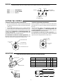
WIRING
11D06 .................... OPEN ON RISE
11D37 .................... CLOSE ON RISE
11D82 .................... S.P.D.T.
RED
WHITE
BLUE
COMMON
CLOSE ON RISE
OF TEMPERATURE
OPEN ON RISE
OF TEMPERATURE
SETTING THE CONTROL
CONTROLS WITH ADJUSTABLE DIFFERENTIAL
1. Insert a screwdriver in the centre slot and turn the dial until
the right hand indicator “B” points to the lowest temperature
of the cycle.
2. Turn the differential adjusting screw “C” until the left hand
indicator “D” points to the highest temperature of the cycle.
The left-hand indicator points to the temperature at which the
contacts open on high limit and low limit applications. On
circulator applications, the left-hand indicator points to the
temperature at which the circulator will start.
On combination low limit and circulator applications, the
left-hand indicator points to the temperature at which the low
limit stops the burner and permits the circulator to run.
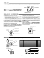
CONTROLS WITH FIXED DIFFERENTIAL
Insert a screwdriver in centre slot “A” and turn the dial until the
fixed indicator “B” points to the highest desired temperature of
the cycle.
The fixed indicator points to the temperature at which the
contacts open on high limit and low limit applications. On
circulator applications, the fixed indicator points to the tem-
perature at which the circulator will start.
On combination low limit and circulator applications, the
fixed indicator points to the temperature at which the low limit
stops the burner and permits the circulator to run.
“B” FIXED
INDICATOR
“A” ADJUSTING
SLOT
“B” FIXED INDICATOR
“C” DIFFERENTIAL
ADJUSTING SCREW
“D” MOVABLE INDICATOR
“A” ADJUSTING
SLOT
Well No. Description A B C
89-0211 1/2" Std. Shank 1-13/16" 3" 3-5/16"
89-0212 1/2" Std. Ext. Shank 3-5/16" 3" 3-5/16"
89-0213 3/4" Std. Shank 1-13/16" 3" 3-5/16"
89-0214 3/4" Std. Ext. Shank 3-5/16" 3" 3-5/16"
89-0215 3/4" Extra Ext. Shank 4-13/16" 3" 3-5/16"
A
B
C
Order wells and heat conductive grease No. 145-0163 separately.
SERVICING
RETAINER CLIP
IMMERSION WELL
CAPILLARY
RETAINER CLIP
Page is loading ...
Page is loading ...
-
 1
1
-
 2
2
-
 3
3
-
 4
4


White Rodgers 11D37 User manual
- Type
- User manual
Ask a question and I''ll find the answer in the document
Finding information in a document is now easier with AI
in other languages
- français: White Rodgers 11D37 Manuel utilisateur
Related papers
-
White Rodgers 11A79-2 User manual
-
-
-
White Rodgers 1127-2 User manual
-
-
-
-
-
-
Other documents
-
Emerson 5C06 User manual
-
resideo L7224U1002 Installation guide
-
Honeywell L7224A,C User manual
-
Baxi Luna 310 Fi Installation And Servicing Instructions
-
-
-
-
Beretta CONNECT AT LE Installer And User Manual
-
Riello Caldariello Condens 25 KIS User manual
-
Breville The Hydro Pro Plus User manual