Riva RS12050-340FP-07 Operating instructions
- Type
- Operating instructions

Word doc. Part # RS12050-340FP-07 © H1 2/27/13 1
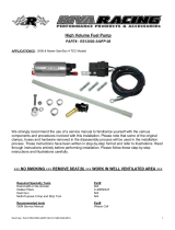
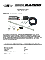
High Volume Fuel Pump
PART# - RS12050-340FP-07
APPLICATION(S): 2007-04 Sea•Doo 4-TEC Models
We strongly recommend the use of a service manual to familiarize yourself with the various
components and procedures involved with this installation. Please note that some of the original
clamps, hoses and hardware removed in the disassembly process will be used in the installation
process. These instructions have been written in step-by-step format and refer to illustrations. Read
through instructions entirely before performing installation. Please follow these step-by-step
instructions and illustrations carefully.
NO SMOKING REMOVE SEAT(S) WORK IN WELL VENTILATED AREA
Required Specialty Tools
Part#
Dremmel® or Die Grinder N/A
Oetiker Pliers C-48550347
Heat Gun N/A
Multi-Purpose Crimp and Strip Tool N/A
Recommended tools
Part#
OEM Service Manual Please Call

Word doc. Part # RS12050-340FP-07 © H1 2/27/13 2
- INSTALLATION INSTRUCTIONS -
Disconnect battery cables. Black first. Red second.
REMOVE FUEL PUMP MODULE
Remove glove box by unsnapping clips (2) at edge
closest to seat.
Access fuel pump module.
Disconnect vent hose
1
from top of fuel pump module.
Remove clip
2
securing fuel supply/return fitting. Remove
fitting from top of fuel pump module.
Cover top of fuel pump module with a shop rag to prevent fuel
spill.
Remove nuts (9) securing fuel pump module in tank.
Raise fuel pump out of fuel in tank. DO NOT REMOVE
COMPLETELY. Tilt forward to drain excess fuel.
Remove fuel pump from tank by lifting and tilting
forward. As end of fuel pump clears tank continue tilting
to allow fuel level sensor to clear opening.
Place a shop rag over top of fuel pump to prevent fuel spill.
Drain fuel pump module thoroughly. Work in clean and
well-ventilated area.
REMOVE STOCK FUEL PUMP
Remove fuel level indicator by lifting straight out of
retaining clip.
1
2

Word doc. Part # RS12050-340FP-07 © H1 2/27/13 3
Disconnect electrical connector from underside of fuel
pump module top. (One clip each side.)
Remove top of fuel pump module by carefully squeezing
each arm (3) inward to release from locking tabs inside
top of metal housing. Note orientation of top prior to
removing.
You may or may not be able to remove the stock fuel
pump from the metal housing. Try pulling up on the
supply tube. If tube comes off of pump or pump cannot
be removed proceed to next step. If fuel pump can be
removed skip next step.
At base of metal housing drill out rivets (2 – 1 per side).
Pull metal base plate out of metal housing enough to
access fuel pump filter. Carefully separate filter from
base plate. NOTE: There will be one gasket and
washer in base plate for fuel filter. Do not lose or
discard.
Pull fuel pump out of top of metal housing. Remove
supply tube and disconnect electrical wires. Note
orientation of fuel supply tube before removing.

Word doc. Part # RS12050-340FP-07 © H1 2/27/13 4
Carefully separate fuel pump filter from rubber spacer at
bottom of stock fuel pump.
Carefully separate rubber spacer from bottom of stock
fuel pump.
INSTALL SUPPLIED FUEL PUMP
Remove used self-locking retaining ring from inside of
rubber spacer. Install supplied new self-locking retaining
ring into rubber spacer.
NOTE: DO NOT REUSE ORIGINAL SELF-LOCKING
RETAINING RING.
Install rubber spacer onto bottom of supplied High
Volume Fuel Pump. TIP: Use a small socket to press
self-locking retaining ring onto fuel pump.

Word doc. Part # RS12050-340FP-07 © H1 2/27/13 5
Install fuel pump filter onto rubber spacer. TIP: Apply
engine oil to flange on rubber spacer to ease installation
of filter.
Connect electrical wires and install fuel supply tube.
NOTE: Be sure fuel supply tube is facing proper
direction and plastic support is in place.
Replace metal base plate and secure to metal housing
using supplied rivets. NOTE: Be sure filter gasket, metal
washer and outer base plate gasket are in place in
metal base plate.
GASKET FIRST WASHER SECOND
Carefully lower fuel pump assembly into metal housing.
NOTE: Fuel pump filter fits one direction only. Be sure
filter is seated squarely in metal base plate and plastic
support is facing proper direction.
Place spring over top of fuel supply tube. Replace fuel
pump module top. Reconnect electrical wire. NOTE: Be
sure that top moves up and down freely.
Carefully replace fuel level indicator. NOTE: Be sure
arm locks in place.

Word doc. Part # RS12050-340FP-07 © H1 2/27/13 6
INSTALL SUPPLIED RELAY MODULE
A wiring diagram reference is provided on the last page
of these instructions.
The supplied relay should be installed in a location
away from direct water spray or water intrusion.
Using supplied hardware secure relay to inside of hull
so that wires hang downward.
MODIFY FUEL PUMP WIRING
Measure sheathing on fuel pump electrical connector 3”
from end. Carefully trim and discard 3” from end of
sheathing. Isolate ‘D’ wire (brown with pink stripe).
NOTE: Wires are identified on connector.
Cut ‘D’ wire 2~3” from connector. Pull ‘D’ wire back out
of sheathing. Feed black wire from relay into sheathing
towards electrical connector. Allow for some slack back
at split in sheathing and trim excess black wire at
connector.
Connect black wire to ‘D’ wire at electrical connector
using supplied heat shrink butt connector. NOTE: DO
NOT USE OPEN FLAME to shrink connector. Use a
heat gun. Direct heat away from fuel tank and
battery.
FRONT
3”
2~3” long
Black Wire
from Relay
Example of ideal
location for relay.
Example of ideal
location for relay.

Word doc. Part # RS12050-340FP-07 © H1 2/27/13 7
Pull sheathing down over butt connector. Reconnect to
fuel pump module.
Direct blue wire from relay to open end of ‘D’ wire (main
wiring harness side). Allow for some slack and trim
excess blue and ‘D’ wires. Connect using supplied heat
shrink butt connector. NOTE: DO NOT USE OPEN
FLAME to shrink connector. Use a heat gun. Direct
heat away from fuel tank.
At division in main wire harness for fuel pump module
connection isolate and splice ‘A’ wire (purple wire with
red stripe). Reconnect using supplied heat shrink butt
connector including red wire from relay. NOTE: DO
NOT USE OPEN FLAME to shrink connector. Use a
heat gun. Direct heat away from fuel tank.
Route relay ground wire (black with eyelet connector)
towards engine and secure to any one of the three
grounding points on front of crankcase. NOTE: Apply
blue Loctite to bolt. Do not over tighten bolt.
Cover relay wires with supplied sheathing. Secure wires
using supplied zip ties and zip tie mounting tabs.
Replace 10amp Fuel Pump fuse with supplied 15amp
fuse.
2007-04 Prior Models
:
Reconnect battery cables. Red first. Black second.
Replace glove box.
Check bilge for tools, rags, etc. Run craft on a flush kit
to check for proper operation.
Fuel Pump
Module Side
Red Relay
Wire
Main Harness
Side
Main
Harness
Side

Word doc. Part # RS12050-340FP-07 © H1 2/27/13 8
RELAY WIRING DIAGRAM REFERENCE
Remember, the water belongs to everyone.
Please ride responsibly and respect the environment!
Technical Support
For answers to questions regarding installation or trouble shooting RIVA Performance Products contact:
RIVA Technical Support directly at (954) 247-0705 or by e-mail at [email protected].
Limited Warranty
RIVA High Volume Fuel Pump Kits carry a 90-day limited warranty to the original purchaser. They are warranted to be free of defects in materials and workmanship under
normal use and service. Customer modified components will be void of warranty. This warranty is limited to defects in the primary components only. Finish and/or wear
marks in or on primary components are not covered under this warranty.
RIVA Racing’s liability is expressly limited to the repair or replacement of the components contained within or associated with this kit. RIVA Racing agrees to repair or at
RIVA’s option, replace any defective unit without charge, if product is returned to RIVA Racing freight prepaid within the warranty period. Any equipment returned which, in
RIVA’s opinion, has been subjected to misuse, abuse, overheating or accident shall not be covered by this warranty.
RIVA Racing shall have no liability for special, incidental or consequential damages or injury to persons or property from any cause arising from the sale, installation or use
of this product.
No other warranty, express or implied, including, but not limited to the implied warranties of merchantability and fitness for a particular purpose, applies. Various states do
not allow for the limitation of incidental or consequential damages and therefore the above exclusion or limitation may not apply to you.
Warranty does not include the expenses related to freight or transportation of parts or compensation for any inconvenience or loss of use while being repaired. A copy of
the original invoice and a Return Authorization Number (RA#) must accompany all warranty claims.
Warranted replacement parts will be returned freight collect.
-
 1
1
-
 2
2
-
 3
3
-
 4
4
-
 5
5
-
 6
6
-
 7
7
-
 8
8
Riva RS12050-340FP-07 Operating instructions
- Type
- Operating instructions
Ask a question and I''ll find the answer in the document
Finding information in a document is now easier with AI
Related papers
-
 Riva RS12050-340FP-08 Operating instructions
-
 Riva RS12050-340FP-08 Operating instructions
-
 Riva RY21060 Operating instructions
-
 Riva RY5-FZ-MB Operating instructions
-
 Riva RY21050 Operating instructions
-
 Riva RY11841-LD-MB Operating instructions
-
Riva Jettrim Seat Cover Operating instructions
-
 Riva RS24130-BES Operating instructions
-
 Riva Pro-Series Operating instructions
-
 Riva RS12050-BFR Operating instructions
Other documents
-
Donaldson X220138 User manual
-
 Mi-T-M Electrode Assy Kit Large Owner's manual
-
CURT 56229 Installation guide
-
Jackson SUPERCHARGER with PowerCard User manual
-
Verona WALL HUNG GAS BOILER User manual
-
 Factory Five Racing Mk3 Roadster Assembly Manual
-
Ford D-213-20 User manual
-
Edelbrock Edelbrock Stg 2 Complete Supercharger #153880, 18-21 Ford Mustang 5.0L W/O Tune Installation guide
-
Chevrolet Impala SS User manual
-
Factory Five Racing Mk4 Roadster Assembly Manual


