CAME DBC 01 Installation guide

Type
Installation guide

This manual is also suitable for

INSTALLATION MANUAL
CORDLESS PHOTOCELL
This symbol indicates sections to be read with particular care.
This symbol indicates sections concerning safety
This symbol indicates notes to communicate to users.
with the following standards:
EN 12978, UNI EN 954-1, CEI EN 60335-1, UNI EN 12453.
“IMPORTANT SAFETY INSTRUCTIONS FOR INSTALLATION”
“CAUTION: IMPROPER INSTALLATION MAY CAUSE SERIOUS DA-
MAGE, FOLLOW ALL INSTALLATION INSTRUCTIONS CAREFULLY”
“THIS MANUAL IS ONLY FOR PROFESSIONAL INSTALLERS OR
QUALIFIED PERSONS”
Legend of symbols
Reference Standards
Description of devices
Designed and manufactured by CAME CANCELLI AUTOMATICI S.p.A. in
compliance with the safety regulations in force.S.p.A.
DBC 01
Protection deviceMade up of two units:
-12/24v AC/DC Infrared receiver.
1 led to signal that battery is run down (when the led on the receiver
ashes, this means that the batteries’ charge will completely run
down in about a month)
-Battery powered infrared transmitter (works on four 1.5V AAA
batteries)
DBC 04
- Infrared repeater, made up of a central photodiode receiver and two
lateral, transmitting photodiodes, with dip switches for selecting the
emitting side.
Battery powered (works on four 1.5V AAA batteries)
DBC 03
- Infrared repeater, made up of a central transmitter photodiode and
two lateral receiver photodiodes, with dip switches for selecting
receiving side.
Battery powered (works on four 1.5 AAA batteries)
TX
TX
RX
RX
RX
TX
GB
DBC 01
DBC 03 - DBC 04
DBC 01 (TX)
Description/Electrical connections and DIP switch
functions
1-Signal present warning led
2-Dip Switch
Dip Switch function
Dip switch 1 in ON position=
12V AC/DC power supply
Dip switch 1 in OFF position=
24V AC/DC power supply
Dip switch 2 in OFF position=
Excludes testing of service
function
(to be used when
TS?? Is not connected)
3- Low battery/open contact
warning led
4-Terminal board for con-
nections
DBC 01 (RX)
Contatto N.O.
C1/C2/C3/C4
10
2
TS
2
1 2 3 4 5 6 7 8 9 10 11 12
1 2 3 4 5 6 7 8 9 10 11 12
05 06 07 08 09 V1 V2 V3
1,5V AAA
1,5V AAA
+
+
-
-
+
+
-
-
-
-
+
+
-
-
+
+
1,5V AAA
1,5V AAA
K
K
K
K
K
K
R13
R13
R15
R15
R22
R22
R23
R23
1
2
1-Battery housing
(four 1.5V AAA batteries)
2-Infrared led
-+
-+
NO
NC
C
1
2
3
4
Before installing you must:
• Make sure that the line voltage is disconnected.
• See that the point, to which the equipment will be mounted, is
in an area protected from any impacts, that the mounting surfa-
ce is solid, and that the mounting on to the surface is carried out
with the proper hardware (bolts, pins, etc).
•Provide for proper electrical cable conduits making sure that
they are free from any mechanical damage.
InstallationTechnical data
Receiver/Transmitter/Repeater





Dimensions and holes pitch
DBC 01 (TX)
Power supply: (4 1.5V AAA batteries)
Draw: 70 µA
Degree of protection: IP 54
Material: PC-ABS UL94V0 / Policarbonato / Marpram mar TPA1 65 NT
Working temperature:
#
#
DBC 01 (RX)
Power supply: 12/ 24 V A.C. - D.C.
Draw: 48 mA
Degree of protection: IP 54
Material: PC-ABS UL94V0 / Policarbonato / Marpram mar TPA1 65 NT
Working temperature:
#
#
Ripetitore DBC 04
Power supply: (4 1.5V AAA batteries)
Draw: 70 µA
Degree of protection: IP 54
Material: PC-ABS UL94V0 / Policarbonato / Marpram mar TPA1 65 NT
Working temperature:
#
#
RipetitoreDBC 03
Power supply: (4 1.5V AAA batteries)
Draw: 70 µA
Degree of protection: IP 54
Material: PC-ABS UL94V0 / Policarbonato / Marpram mar TPA1 65 NT
Working temperature:
#
#
Fig.B
Fig.A
Example of a standard installation and relative
Dip Switch configuration
DBC 01(TX)
Does NOT
require
confi guration
DBC 04 Repeater
DBC 03 Repeater
1-Battery housing
(Four 1.5V AAA batteries)
2-Infrared led,
selectable through the DIP
switch
3-Low battery warning led
4-Dip switch for selecting tran-
smission led
When Dip switch 1 ON, left-hand
led is active
When Dip switch 2 ON, right-
hand led is active
1-Battery housing
(Four 1.5V AAA batteries)
2-Infrared led,
selectable through the DIP
switch
3-Low battery warning led
4-Dip switch for selecting tran-
smission led
When Dip switch 1 ON, left-hand
led is active
When Dipswitch 2 ON, right-hand
led is active
+
+
-
-
+
+
-
-
-
-
+
+
-
-
+
+
K
K
K
K
K
K
2
1
1
4
2
3
+
+
-
-
+
+
-
-
-
-
+
+
-
-
+
+
K
K
K
K
K
K
2
1
1
2
4
3
DBC 01(RX)
Does NOT
require
confi guration
DBC 04
Dip 1 set to ON
Dip 2 set to OFF
DBC 03
Dip 1 set to OFF
Dip 2 set to ON
DBC 01(RX)
DBC 01(TX)
DBC 01(TX)*
DBC 01(RX)**
DBC 04*
DBC 03*
Note: When using DBC 01, DBC 03 and DBC 04, as explained
in the two preceding confi gurations, remember to remove
the bridge on DBC 01 (TX)
*With DB-L/DB-LN columns
**With G02802 photocell support
DBC 04*
DBC 03*
*With DB-L/DB-LN columns
DBC 01(TX)
Does NOT
require
confi guration
DBC 01(RX)
Does NOT
require
confi guration
DBC 04
Dip 1 set to ON
Dip 2 set to OFF
DBC 03
Dip 1 set to OFF
Dip 2 set to ON
• Verifi care Make sure that the distance between the two
photocells is not greater than 10 metres, and that they are
perfectly aligned, before installing.
• Fix the bottoms of the photocells as follows:
- for the DB-L posts, use the UNI 6954 3.9x3 stainless
steel screws (found in the DB-L kit);
- for fi xing on the wall or on steel, use the UNI 6954
3.9x32 screws with the supplied nogs .
• Insert the batteries (you will need four 1.5V AAAs) into
the transmitter and the repeaters making sure the polarity
matches that shown on the card.
• Set the leds to (ON/OFF) depending on the make up of the
system. Connect the DBC01 (RX) as shown in the fi gure on
page 2.
• Close the
devices by
hooking the cover
at the top and
xing it in place
with the supplied
screws .
Assembly
Problems
- The led on the receiver is fl ashing: the transmitter battery is run
down
- The led on the receiver stays on: signal is interrupted due to
transmitter malfunction.
Demolition and disposal
Manufacturer’s declaration
Declaration of conformity
la CAME Cancelli Automatici S.p.A.
via Martiri della Libertà, 15
31030 Dosson di Casier - Treviso - ITALY
tel (+39) 0422 4940 - fax (+39) 0422 4941
internet: www.came.it - e-mail: [email protected]
Declare under their own responsibility that the following
products for gate and garage door automation called:
Are compliant with essential requirements and with pertinent
regulations established by the following directives and to the
applicable parts of the standards listed below:
Electromagnetic compatibility directive 2004/108/CE
Electrical equipment designed for use within certain voltage
limits directive 2006/95/CE
Machinery directive 98/37/EC
EN 61000-6-1
EN 61000-6-2
EN 61000-6-3
EN 60335-1
EN 13241-1
DBC 01- DBC 03-DBC 04
L’amministratore delegato
Sig. Gianni Michielan
Product disposal
Our products are made up of various types of materials. Most of
them (aluminium, plastics, iron,
electrical wires, etc.) may be disposed of in normal garbage
collection bins and can be recycled by disposing of in specifi c
recyclable material collection bins and disposal in authorized
centres.
Other components (electrical boards, remote control batteries,
etc.), however, may contain polluting substances.
They should therefore be removed and given to qualifi ed service
companies for proper disposal.
Prior to disposal, it is always advisable to check specifi c regulations
in force in the place of disposal.
PLEASE DISPOSE OF PROPERLY!
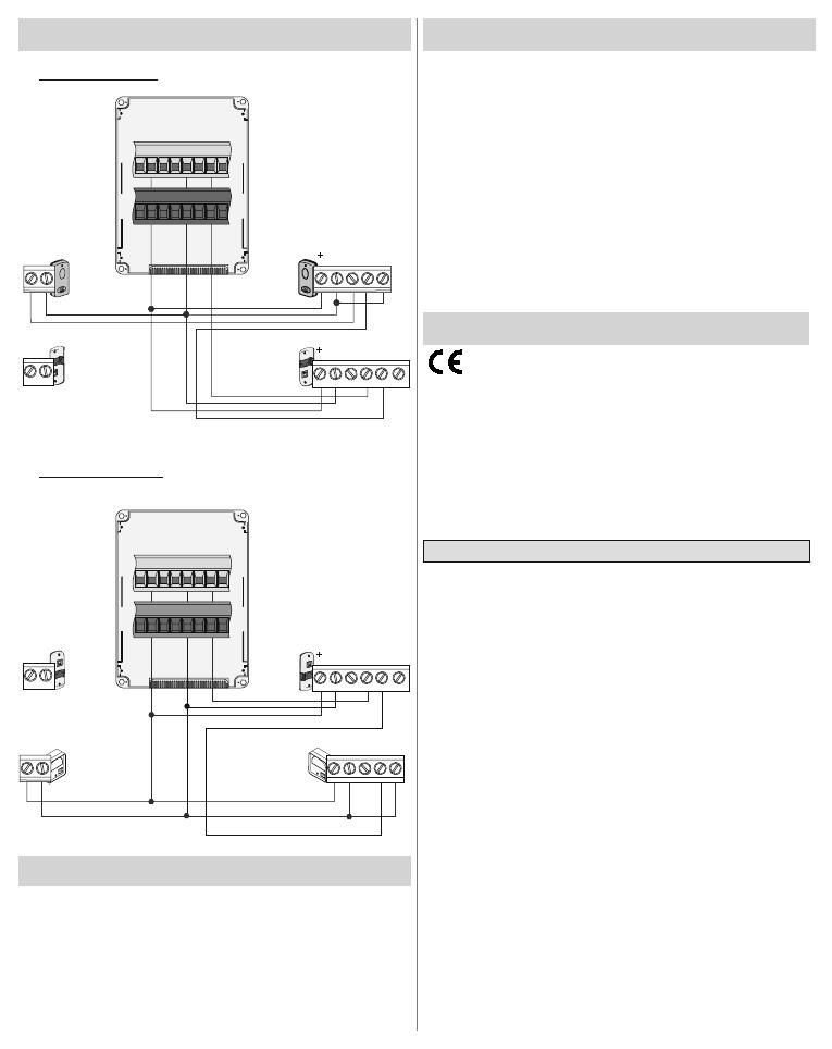
Connecting DBC 01 with DIR/DOC
Rx
TX
2
10 2 TX
C
NC
-
0
2
C1
10
2C1
Tx
Rx
Tx
DIR DIR
24 0 TS
C
NC
-
DIW
NO
DIW
24
0
0
2
C1
10
2C1
Tx
Rx
Tx
DOC
24 0 TS
C
NC
-
DIW
NO
DIW
24 0 N0
C
NC
Rx
DBC 01 with DIR
DBC 01 with DOC
119RU82 ver 0.1 - 09/2008
  • Page 1 1
  • Page 2 2
  • Page 3 3
  • Page 4 4
  • Page 5 5
  • Page 6 6
  • Page 7 7
  • Page 8 8
  • Page 9 9
  • Page 10 10
  • Page 11 11
  • Page 12 12
  • Page 13 13
  • Page 14 14
  • Page 15 15
  • Page 16 16
  • Page 17 17
  • Page 18 18
  • Page 19 19
  • Page 20 20
  • Page 21 21
  • Page 22 22
  • Page 23 23
  • Page 24 24

CAME DBC 01 Installation guide

Type
Installation guide
This manual is also suitable for

Ask a question and I''ll find the answer in the document

Finding information in a document is now easier with AI