Page is loading ...

FS-97E
Full-size PICMG CPU Card
User’s Manual
Edition 1.2
2009/7/14

FS-97E User’s Manual
-1-
Copyright
Copyright 2009, all rights reserved. This document is copyrighted and all rights are
reserved. The information in this document is subject to change without prior notice
to make improvements to the products.
This document contains proprietary information and protected by copyright. No part
of this document may be reproduced, copied, or translated in any form or any means
without prior written permission of the manufacturer.
All trademarks and/or registered trademarks contains in this document are property
of their respective owners.
Disclaimer
The company shall not be liable for any incidental or consequential damages
resulting from the performance or use of this product.
The company does not issue a warranty of any kind, express or implied, including
without limitation implied warranties of merchantability or fitness for a particular
purpose.
The company has the right to revise the manual or include changes in the
specifications of the product described within it at any time without notice and
without obligation to notify any person of such revision or changes.
Trademark
All trademarks are the property of their respective holders.
Any questions please visit our website at TUhttp://www.commell.com.twUT

FS-97E User’s Manual
-2-
Packing List:
Please check the package content before you starting using the board.
Hardware:
FS-97E Full-size PICMG CPU Card x 1
Cable Kit:
SATA Cable x 2
DVI module with DVI Cable x 1
(FS-97EXDG & FS-97EXDG2)
FDD cable x 1
PS/2 Keyboard & Mouse Cable x 1
HD Audio Port Cable x 1
USB Cable x 2
40-pin ATA100 IDE cable x 1
ATX cable x 1
CPU Cooler x 1

FS-97E User’s Manual
-3-
COM & Printer cable x 1
(FS-97EXG & FS-97EXDG)
Com Cable x 1
(FS-97EXG2 & FS-97EXDG2)
Printer cable x 1
(FS-97EXG2 & FS-97EXDG2)
HDTV Port Cable x 1 (Optional)
Printed Matters:
Driver CD x 1 (including User’s Manual)
VT-6421_RAID & ICH9M_AHCI disk driver x1

FS-97E User’s Manual
-4-
Index
Chapter 1 <Introduction>.......................................................................................7
1.1 <Product Overview>..................................................................................7
1.2 <Product Specification>.............................................................................8
1.3 <Mechanical Drawing>............................................................................10
1.4 <Block Diagram>.....................................................................................11
Chapter 2 <Hardware Setup>...............................................................................12
2.1 <Connector Location>.............................................................................12
2.2 <Connector Reference>..........................................................................13
2.2.1 <Internal Connectors> ................................................................13
2.2.2 <External Connectors>...............................................................13
2.3 <Jumper Location & Reference>.............................................................14
2.4 <CPU and Memory Setup>.....................................................................15
2.4.1 <CPU Setup>..............................................................................15
2.4.2 <Memory Setup> ........................................................................16
2.5 <CMOS Setup>.......................................................................................17
2.6 <Serial ATA Interface>.............................................................................18
2.7 <Ethernet Interface>................................................................................19
2.8 <Onboard Display Interface> ..................................................................20
2.8.1 <Analog VGA Interface>.............................................................20
2.8.2 <Digital Display>.........................................................................21
2.8.3 <HDTV Interface>.......................................................................25
2.8.4 <DVI Interface >..........................................................................26
2.9 <Integrated Audio Interface>...................................................................27
2.10 <GPIO Interface>..................................................................................29
2.11 <Power and Fan Installation>................................................................30
2.11.1 <Power connectors>.................................................................30
2.11.2 <Fan Connectors> ....................................................................30
2.11.3 <ATX Power Mode>..................................................................32
2.12 <Switch and Indicator>..........................................................................33

FS-97E User’s Manual
-5-
Chapter 3 <System Setup> ..................................................................................34
3.1 <OS installation Guide> ..........................................................................34
3.2 <Audio Configuration>.............................................................................35
3.3 <Video Memory Setup>...........................................................................36
3.4 <Display Properties Setting>...................................................................37
Chapter 4 <BIOS Setup> ......................................................................................39
Appendix A <I/O Port Pin Assignment>..............................................................41
A.1 <Serial ATA Port>....................................................................................41
A.2 <IrDA Port>.............................................................................................41
A.3 <SMBUS Port> .......................................................................................42
A.4 <Serial Port 2>........................................................................................42
A.5 < RS-232, RS-422, RS-485 & IrDA >......................................................43
A.6 <Parallel Port>........................................................................................44
A.7 <LAN Port>.............................................................................................44
A.8 <USB Interface> .....................................................................................44
A.9 <DVI Port>..............................................................................................45
A.10 <PS/2 Keyboard & Mouse Port>...........................................................45
Appendix B <Flash BIOS>....................................................................................46
B.1 <Flash Tool> ...........................................................................................46
B.2 <Flash BIOS Procedure>........................................................................46
Appendix C <System Resources>.......................................................................47
C.1 <Direct Memory Access (DMA)> ............................................................47
C.2 <Direct Memory Access (IRQ)>..............................................................47
C.3 <Input /Output (IO)>................................................................................48
C.4 <Memory Address Map> ........................................................................50
Appendix D <Programming GPIO’s>...................................................................51
Appendix E <Programming Watchdog Timer>...................................................52
Contact Information..............................................................................................53

FS-97E User’s Manual
-6-
(This page is left for blank)

FS-97E User’s Manual
-
7-
Chapter 1 <Introduction>
1.1 <Product Overview>
FS-97E the new generation of the Full-size PICMG CPU Card, supports Intel Penryn
Processor for 667/800/1066 MHz front side bus and features Intel GM45 and ICH9M
chipset, integrated GMA 4500MHD graphics, DDR3 memory, REALTEK ALC888
High Definition Audio, Serial ATA and two Intel Gigabit LAN.
Intel Penryn Processor
The board supports Intel Penryn processor with 667/800/1066 MHz front side bus,
L2 Cache: All specification depends on the CPU(1M/2M/3M/4M/6M). To provides
more powerful performance than before.
New features for Intel GM45 chipset
The board integrates Intel GM45 and ICH9M chipset, to provide new generation of
the mobile solution, supports Intel GMA 4500MHD graphics, DDR3 800/1066MHz
memory, built-in high-speed mass storage interface of serial ATA, High Definition
Audio with 2 channels surrounding sound.
All in One multimedia solution
Based on Intel GM45 and ICH9M chipset, the board provides high performance
onboard graphics, 24-bit dual channel LVDS interface, HDTV and 2 channels High
Definition Audio, to meet the very requirement of the multimedia application.
Flexible Extension Interface
The board provides one PCI Express mini card (FS-97EXDG & FS-97EXDG2 only),
two PCI Express mini card (FS-97EXG & FS-97EXG2 only) one mini-PCI socket
and one CF socket.

FS-97E User’s Manual
-
8-
1.2 <Product Specification>
General Specification
Form Factor Full-size PICMG CPU Card
PICMG version 1.0 (Rev. 2.0), PCI version 2.0 compliant
CPU Support Intel Penryn Processor
Package type: Micro-FCPGA478 (Socket-P)
L2 Cache: All specification depends on the CPU (1M/2M/3M/4M/6M)
Front side bus: 667/800/1066 MHz
Memory 2 x 800/1066MHz DDRIII 204-pin SO-DIMM up to 8GB
Chipset Intel® GM45 and ICH9M (82801IBM)
BIOS Phoenix-Award v6.00PG 8Mb SPI flash BIOS
Green
Function
Power saving mode includes doze, standby and suspend modes.
ACPI version 2.0 and APM version 1.2 compliant
Watchdog
Timer
System reset programmable watchdog timer with 1 ~ 255
sec./min. of timeout value
Real Time
Clock
Chipset integrated RTC with onboard lithium battery
IDE UltraATA133 IDE interface supports up to 2 ATAPI devices
One 40-pin IDE port onboard with VT-6421
Serial ATA Intel® ICH9M built-in 3 x SATAII interface up to 300MB/s
VIA VT-6421 built-in 2 x SATAI interface up to 150MB/s
(support RAID 0,1)
Multi-I/O Port
Chipset Intel® ICH9M with Winbond® W83627DHG controller
Serial Port Two RS232 and one jumper selectable RS232/422/485
Parallel Port One internal bi-direction parallel port with SPP/ECP/EPP mode
Floppy Port One internal Floppy port
USB Port 8 x Hi-Speed USB 2.0 ports with 480Mbps of transfer rate
IrDA Port One IrDA compliant Infrared interface supports SIR
K/B & Mouse PS/2 keyboard and mouse port on bracket
GPIO One 12-pin Digital I/O connector with 8-bit programmable
VGA Display Interface
Chipset Intel® GM45 & ICH9M
Memory Up to 1024MB shared with system memory
Display Type CRT, LCD monitor with analog display, DVI, HDTV
Connector External DB15 female connector
Onboard 40-Pin LVDS connector
Onboard 26-Pin DVI connector (FS-97EXDG/XDG2)
Onboard 9-Pin TV-out connector

FS-97E User’s Manual
-
9-
Ethernet Interface
Chipset Intel 82574L Gigabit Ethernet controller
Type Triple speed 10/100/1000Base-T
auto-switching Fast Ethernet
Full duplex, IEEE802.3U compliant
Connector External two RJ45 connector with LED on rear I/O panel
Audio Interface
Chipset Intel® ICH9M with Realtek ALC888 HD Audio
Intel High Definition Audio compliance
Interface 2 channels sound output
Connector Internal 10-pin header for line-in/-out, MIC-in, 4-pin for CD-IN
Solid State Disk Interface
Flash Type Compact Flash TypeII for Compact Flash Card with VT-6421
ISA Interface
ISA Bridge Winbond W83628G & W83629G
Function I/O & IRQ supported only, no support DMA & bus mastering
Expansive Interface
Mini PCI Up to 2 x Mini PCI socket (optional)
1 x Mini PCI (standard)
PCI express
Mini card
Up to 3 x PCI express mini card socket (optional)
1 x PCI express mini card socket (FS-97EXDG/FS-97EXDG2)
2 x PCI express mini card socket (FS-97EXG/FS-97EXG2)
Power and Environment
Power
Requirement
+5V, +12 DC input & 5V
SB
Requirement
Dimension 338 (L) x 122 (W) mm
Temperature Operating within 0 ~ 60 P
o
P
C (32 ~ 140P
o
P
F)
Storage within -20 ~ 85
P
o
P
C (-4 ~ 185P
o
P
F)
Ordering Code
FS-97EXG Onboard VGA, LVDS, HDTV, IDE, CF, SATA, COM, USB2.0,
Mini PCI, HD Audio, 2 x PCI Express mini card, 1 x Gigabit
LAN.
FS-97EXG2 Onboard VGA, LVDS, HDTV, IDE, CF, SATA, COM, USB2.0,
Mini PCI, HD Audio, 2 x PCI Express mini card, 2 x Gigabit
LAN.
FS-97EXDG Onboard VGA, LVDS, HDTV, IDE, CF, SATA, COM, USB2.0,
Mini PCI, HD Audio, DVI, 1 x PCI Express mini card, 1 x
Gigabit LAN.
FS-97EXDG2 Onboard VGA, LVDS, HDTV, IDE, CF, SATA, COM, USB2.0,
Mini PCI, HD Audio, DVI, 1 x PCI Express mini card, 2 x
Gigabit LAN.

FS-97E User’s Manual
-
10-
1.3 <Mechanical Drawing>

FS-97E User’s Manual
-
11-
1.4 <Block Diagram>
ICH9M
8 x USB2.0 ports
1 x Mini PCI
3 x SATAII
300MB/S
2 x LAN Intel 82574L
BIOS
SPI
1 x CF
1 x LVDS
Intel GMA X4500MHD
1 x PCI express mini card
Intel Penryn Processor
2 x 204-pin DDR3 SO-DIMM
800/1066MHz up to 8GB
GM45
1 x PCI ex
p
ress mini card
ALC888 HD Audio
1 x RS422/485/232/IR
1 x com, FDD, LPT & GPIO
W83627DHG
1 x HDTV
1 x DVI (FS-97EXDG/G2)
1 x IDE
2 x SATAI
150MB/S
VT
-6421
ISA Bridge
(FS-97EXG/G2)
(second optional)
(second optional)

FS-97E User’s Manual
-
12-
JFRNT
CN_DVI
CN_USB1/2/3/4
IDE
CN_HDTV
CN_DIO
DC_IN
CPUFAN
CN_INV
Chapter 2 <Hardware Setup>
2.1 <Connector Location>
MINIPCI1
MINI_CARD2
CN_AUDIO
CD_IN
CN_COM1/2
CN_LVDS
FDD
CN_ATKB
CN_PS
SYSFAN
MINIPCI2
CF
CN_LPT
MINI_CARD1
SATA1/2/3/4/5
SO-DIMM2
CN_IR
CN_SMBUS
MINI_CARD3
(optional)
(optional)
PS2 LAN2 LAN1 CRT
FS-97EXG2 & FS-97EXDG2
PS2 COM LAN1 CRT
FS-97EXG & FS-97EXDG

FS-97E User’s Manual
-
13-
2.2 <Connector Reference>
2.2.1 <Internal Connectors>
Connector Function Remark
CPU Socket 478 for socket-P CPU
SO-DIMM1/2 204-pin DDR3 SO-DIMM socket
IDE 40-pin primary IDE connector
CN_LPT 26-pin LPT port connector
FDD 34-pin floppy connector
SATA1/2/3/4/5 7-pin Serial ATA connector
DC_IN 4-pin AT power supply connector
CN_PS 3-pin power input connector
CN_AUDIO 5 x 2-pin audio connector
CD_IN 4-pin CD-ROM audio input connector
CN_DIO 6 x 2-pin digital I/O connector
CN_USB 5 x 2-pin USB connector
CPUFAN 4-pin CPU cooler fan connector
SYSFAN 3-pin system cooler fan connector
CN_DVI 13 x 2-pin DVI interface (FS-97EXDG/G2)
CN_HDTV 5 x 2-pin HDTV interface
CN_LVDS 20 x 2-pin LVDS connector
CN_INV 5-pin LCD inverter connector
CN_IR 5-pin IrDA connector
CN_ATKB 5-pin AT keyboard connector
JFRNT 14-pin front panel switch/indicator
connector
MiniPCI 124-pin Mini-PCI socket Type IIIA
PCI express
mini card
52-pin PCI express mini card socket
COM 1/2 Serial port 1/2 connector (FS-97EXG2/XDG2)
COM 2 Serial port 2 connector (FS-97EXG/XDG)
2.2.2 <External Connectors>
Connector Function Remark
CRT DB15 VGA connector
PS2 PS2 keyboard & mouse
RJ45_1/2 RJ45 LAN 1/2 connector (FS-97EXG2/XDG2)
RJ45_1 RJ45 LAN 1 connector (FS-97EXG/XDG)
COM 1 Serial port 1 connector (FS-97EXG/XDG)

FS-97E User’s Manual
-
14-
2.3 <Jumper Location & Reference>
Jumper Function
JRTC CMOS Operating/Clear Setting
JVLCD Panel Voltage Setting
JAT Power mode select
JCSEL1/2 CN_COM2 RS-232 RS422 RS485 Setting / CN_IR IrDA Setting
Jumper: JAT
Type: onboard 3-pin header
JAT Mode
1-2 AT Mode
2-3 ATX Mode
Default setting: 2-3
JVLCD
JCSEL2
JRTC
JCSEL1
JAT
1
3

FS-97E User’s Manual
-
15-
2.4 <CPU and Memory Setup>
2.4.1 <CPU Setup>
The board comes with the socket 478 for Intel Core 2 Duo socket-P processor only
it supports new generation with 667/800/1066 MHz of front side bus. Please follow
the instruction to install the CPU properly.
1. Use the flat-type
screw drive to unlock
the CPU socket
Unlock wa
y
Check
p
oint
2. Follow the pin direction to install
the processor on the socket
3. Lock the socket
4. Socket P has 478 pins, but is not
pin-compatible with Socket P
CPU.
Socket-P CPU
Check point

FS-97E User’s Manual
-
16-
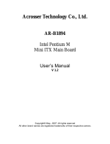
2.4.2 <Memory Setup>
The board provides two 204-pin DDR3 SO-DIMM to support 800/1066 MHz memory
module up to 8GB. Non-ECC, unbuffered memory is supported only, dual channel
technology is enabled automatically for higher performance.
SO-DIMM2

FS-97E User’s Manual
-
17-
2.5 <CMOS Setup>
The board’s data of CMOS can be setting in BIOS. If the board refuses to boot due to
inappropriate CMOS settings, here is how to proceed to clear (reset) the CMOS to its
default values.
Jumper: JRTC
Type: Onboard 3-pin jump
JRTC Mode
1-2 Clear CMOS
2-3 Normal Operation
Default setting: 2-3
JRTC
1
3

FS-97E User’s Manual
-
18-
2.6 <Serial ATA Interface>
Based on Intel ICH9M, the board provides three Serial ATAII interfaces with up to
300MB/s of transfer rate and support AHCI.
Based on VIA VT-6421, the board provides two Serial ATAI interfaces with up to
150MB/s of transfer rate and support RAID 0,1.
SATA1/2 support RAID 0,1
SATA 3/4/5 support AHCI

FS-97E User’s Manual
-
19-
2.7 <Ethernet Interface>
The board integrates with two Intel 82574L Gigabit Ethernet controllers. The Intel
Gigabit Ethernet supports triple speed of 10/100/1000Base-T, with IEEE802.3
compliance and Wake-On-LAN supported.
RJ45_1/2
/