Page is loading ...

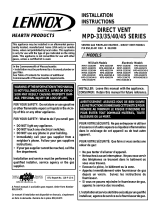
1
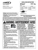
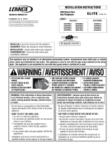
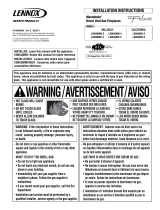
NOTE: DIAGRAMS & ILLUSTRATIONS NOT TO SCALE.
In Canada
THE CONVERSION SHALL BE CARRIED OUT
IN ACCORDANCE WITH THE REQUIREMENTS
OF THE PROVINCIAL AUTHORITIES HAVING
JURISDICTION AND IN ACCORDANCE WITH
THE REQUIREMENTS OF THE CAN1-B149.1
AND .2 INSTALLATION CODE.
LA CONVERSION DEVRA ÊTRE EFFECTUÉE
CONFORMÉMENT AUX RECOMMANDATIONS
DES AUTORITÉS PROVINCIALES AYANT
JURIDICTION ET CONFORMÉMENT AUX
EXIGENCES DU CODE D'INSTALLATION CAN1-
B149.1 ET.2.
This Gas Conversion Kit contains all of the
necessary components needed to complete the
conversion of an appliance from the use of one
type of gas to the use of another, including
labeling that must be affixed to ensure safe
operation.
ALWAYS REFER TO THE APPLIANCE INSTAL-
LATION AND HOMEOWNERS CARE AND OP-
ERATION DOCUMENTS BEFORE COMPLET-
ING A CONVERSION. ALL WARNINGS, CAU-
TIONS AND DETAILED INSTRUCTIONS CON-
TAINED THEREIN ARE APPLICABLE TO THIS
DOCUMENT.
Figure 1
GAS APPLIANCE
KITS AND ACCESSORIES
GAS CONVERSION KIT (FGCK)
Pressure
Regulator
Remove
These
Components
SIT VALVE
To complete the conversion proceed as follows:
Note: After converting the valve and gas compo-
nents, refer to the appliance installation and
homeowners care and operation instructions to
adjust the air shutter opening for the gas type used.
CAUTION: The gas supply shall be shut off
prior to disconnecting the electrical power,
before proceeding with the conversion.
Step 1. Turn off the gas supply to the appli-
ance. Remove the front glass door/frame (if
used) from the appliance. Access the control
compartment.
Step 2. Carefully remove the logs. Exercise
care as not to break the logs.
Step 3. Locate the screws securing the burner
(tray) to the appliance. Remove the burner
and retain the securing screws.
Millivolt Appliances
Step 4. SIT Systems - Refer to
Figure 1
. Using
a Torx T20, or a flat screwdriver, remove and
discard the three pressure regulator mounting
screws. Remove the pressure regulator, spring,
poppet, diaphragm and bushing.
Discard all removed components. Ensure the
rubber gasket installed on the back of the
replacement pressure regulator is properly
positioned and install the new pressure regula-
tor using the new screws supplied with this kit.
Tighten screws to 25 In. lb. torque.
WARNING: THIS CONVERSION KIT SHALL BE IN-
STALLED BY A QUALIFIED SERVICE AGENCY IN AC-
CORDANCE WITH THE MANUFACTURER'S INSTRUC-
TIONS AND ALL APPLICABLE CODES AND REQUIRE-
MENTS OF THE AUTHORIZED AGENCY HAVING JURIS-
DICTION. IF THE INFORMATION IN THESE INSTRUC-
TIONS ARE NOT FOLLOWED EXACTLY, A FIRE, EXPLO-
SION OR PRODUCTION OF CARBON MONOXIDE MAY
RESULT CAUSING PROPERTY DAMAGE, PERSONAL
INJURY OR LOSS OF LIFE. THE INSTALLATION IS NOT
PROPER AND COMPLETE UNTIL THE OPERATION OF
THE CONVERTED APPLIANCE IS CHECKED AS SPECI-
FIED IN THE OWNER INSTRUCTIONS SUPPLIED WITH
THE KIT.
AVERTISSEMENT: CET ÉQUIPEMENT DE CONVERSION SERA
INSTALLÉ PAR UNE AGENCE QUALIFIÉE DE SERVICE
CONFORMÉMENT AUX INSTRUCTIONS DU FABRICANT ET
TOUTES EXIGENCES ET CODES APPLICABLES DE L'AUTORISÉS
AVOIR LA JURIDICTION. SI L'INFORMATION DANS CETTE
INSTRUCTION N'EST PAS SUIVIE EXACTEMENT, UN FEU,
EXPLOSION OU PRODUCTION DE PROTOXYDE DE CARBONE
PEUT RÉSULTER LE DOMMAGES CAUSER DE PROPRIÉTÉ,
PERTE OU BLESSURE PERSONNELLE DE VIE. L'AGENCE
QUALIFIÉE DE SERVICE EST ESPONSABLE DE L'INSTALLATION
PROPRE DE CET ÉQUIPMENT. L'INSTALLATION N'EST PAS
PROPRE ET COMPLÉTE JUSQU'À L'OPÉRATION DE L'APPAREIL
CONVERTI EST CHÉQUE SUIVANT LES CRITÈRES ÉTABLIS
DANS LES INSTRUCTIONS DE PROPRIÉTAIRE PROVISIONNÉES
AVEC L'ÉQUIPEMENT.
750,018M
REV. D 07/2007
Step 5. Honeywell Systems - See
Figure 2
.
Remove the black thread-protecting cap. Re-
move the conversion flip cap by turning it
counterclockwise. Invert the flip cap so that the
letters associated with the desired gas type are
positioned closest to the valve body.
NG is for natural gas and LP is for propane.
Tighten the flip cap by turning it clockwise.
Replace the black thread-protecting cap.

2NOTE: DIAGRAMS & ILLUSTRATIONS NOT TO SCALE.
Electronic Appliances
Step 7. Honeywell Electronic Valves - See
Figure 7
. Remove the slotted cap screw, o-
ring, pressure-regulating adjusting screw and
spring. Retain all parts for possible later use.
Install new components from this kit. Black
cap and red spring for propane gas units.
Silver cap and stainless steel spring fro natural
gas units.
Figure 6
Figure 7
Note: If the ignitor assembly is damaged, a replacement kit is available, order Catalog Number 87L54.
Spring
Adjusting
Screw
Slotted
Cap
PSI
OFF
I
ON
CONTROL
IGNITE
Test
Port
Retaining
Clip
Ignitor
Assembly
Pilot
Assembly
Pilot
Orifice
Flare Nut
Figure 3
Pilot
Orifice
Figure 2
Flip Cap
Thread
Protector
HONEYWELL
VALVE
Figure 4
³⁄₈" Min
(9 mm)
Hood
Pilot
Nozzels
Ignitor Rod
Step 6. Refer to
Figure 3
and remove the pilot
hood assembly to access the hexed pilot ori-
fice. Using a (4mm) Allen wrench, remove and
replace the orifice with the one provided with
this kit.
Figure 4
shows the pilot reas-
sembled, with proper flame.
Figure 5
shows
a typical pilot to burner relationship.
Step 8. Refer to
Figure 6
and replace the pilot
orifice as follows: Remove the ignitor assem-
bly retainer clip, and carefully remove the
ignitor assembly. Exercise extreme care to
prevent damage to or breakage of the ignitor
assembly. Remove the screw securing the
pilot assembly to its mounting bracket. Back
off the flare nut at the end of the pilot gas line
to free the pilot assembly from the gas line.
Remove the pilot orifice and replace it with the
one provided with this conversion kit. Rein-
stall the pilot assembly by reversing the steps
detailed here.
When reinstalling the ignitor assembly, use
extreme care to prevent damage and break-
age. Do not apply any leverage to the ignitor
assembly while restoring the retainer clip to
its original position.
Pilot
Burner
Figure 5
(Millivolt LMBV 36 Shown)

3
NOTE: DIAGRAMS & ILLUSTRATIONS NOT TO SCALE.
Figure 8
ALL FIXED SETTING SIT VALVES
Millivolt Appliances
Step 9. SIT Systems - Refer to
Figure 1
. Using
a Torx T20, or a flat screwdriver, remove and
discard the three pressure regulator mounting
screws. Remove the pressure regulator, spring,
poppet, diaphragm and bushing.
Discard all removed components. Ensure the
rubber gasket installed on the back of the
replacement pressure regulator is properly
positioned and install the new pressure regula-
tor using the new screws supplied with this kit.
Tighten screws to 25 In. lb. torque.
Step 10. Refer to
Figure 3
and remove the
pilot hood assembly to access the hexed pilot
orifice. Using a (4mm) Allen wrench, remove
and replace the orifice with the one provided
with this kit.
Figure 4
shows the pilot reas-
sembled, with proper flame.
Figure 5
shows
a typical pilot to burner relationship.
Electronic Appliances
Step 11. SIT Systems - See
Figure 8
. Using a
Torx T20, or a flat screwdriver, remove and
discard the three pressure regulator mounting
screws. Remove the pressure regulator, spring,
poppet, diaphragm and bushing. Discard all
removed components.
Using a standard tin snip cutting tool, proceed
to trim shoulder off of the regulator provided
with the kit. Ensure the rubber gasket installed
on the back of the replacement pressure regu-
lator is properly positioned and install the new
modified pressure regulator using the new
screws supplied with this kit. Tighten screws to
25 In. lb. torque.
Step 12. Refer to
Figure 6
and replace the pilot
orifice as follows: Remove the ignitor assem-
bly retainer clip, and carefully remove the igni-
tor assembly. Exercise extreme care to pre-
vent damage to or breakage of the ignitor
assembly. Remove the screw securing the
pilot assembly to its mounting bracket. Back
off the flare nut at the end of the pilot gas line to
free the pilot assembly from the gas line.
Remove the pilot orifice and replace it with the
one provided with this conversion kit. Rein-
stall the pilot assembly by reversing the steps
detailed here.
When reinstalling the ignitor assembly, use
extreme care to prevent damage and break-
age. Do not apply any leverage to the ignitor
assembly while restoring the retainer clip to
its original position.
Figure 9
All Models
Step 13. Unscrew the orifice from the manifold
and replace it with the one provided with this kit
(
Figure 9
).
Step 14. Reassemble all removed compo-
nents by reversing the procedures outlined in
the preceding steps. Use pipe joint compound
or Teflon tape on all pipe fittings before install-
ing (ensure propane resistant compounds are
used in propane applications, do not use pipe
joint compounds on flare fittings). Adjust the
air shutter opening on the burner tube, refer to
Note
on page 1.
Step 15. Attach appropriate conversion kit
label (
Figure 10
) next to the rating plate on the
appliance. Attach the installer conversion
label next to the gas valve, after filling out the
information on the label. Refer to the Installa-
tion Instructions for required input rating.
Figure 10
THIS APPLIANCE HAS BEEN CONVERTED TO:
NATURAL GAS
INPUT BTU/HR – 50,000
MANIFOLD PRESSURE – 3.5"
ORIFICE SIZE – (0.130)
THIS APPLIANCE HAS BEEN CONVERTED TO:
PROPANE/LPG
INPUT BTU/HR – 50,000
MANIFOLD PRESSURE – 10"
ORIFICE SIZE – (0.080)
Step 18. For detailed Lighting Instructions,
refer to the Homeowners/Care And Operations
instructions.
Inlet Gas Supply Pressure
Fuel # Minimum Maximum
Propane
Natural
(2.74 kPa)
11.0" WC 13.0" WC
(3.23 kPa)
(1.24 kPa)
4.5" WC 10.5" WC
(2.61 kPa)
Step 16. Turn on gas supply and test for gas
leaks, using a gas leak test solution (also
referred to as bubble leak solution).
Step 17. Attach manometer to the manifold
side pressure test fitting (¹⁄₄" Allen wrench for
Electric units) and adjust screw until pressure
reads 3.5 inches water column (6.54 MmHg)
for natural gas, and 10.0 inches water column
(18.69 MmHg) for propane gas. Refer to the
Installation Instructions and the Table below.
Modified Kit
Pressure Regulator
- After Trim
Remove
These
Components
SIT VALVE
Kit Pressure
Regulator - Before
Trim

4NOTE: DIAGRAMS & ILLUSTRATIONS NOT TO SCALE.
Printed in U.S.A. © 2000 by Lennox Hearth Products
P/N 750,018M REV. D 07/2007
Lennox Hearth Products reserves the right to make changes at any time, without notice, in design, materials, specifications, prices and also to discontinue colors, styles and products.
Consult your local distributor for fireplace code information.
1110 West Taft Avenue •Orange, CA 92865
/