Masport DELUXE LE Owner's manual
- Category
- Barbecues & grills
- Type
- Owner's manual
This manual is also suitable for

559802 - Masport 4/6 Burner 210 Series - May 2015 PANTONE 648C
www.masport.com Part No: 559802.F.0
MASPORT 4/6 BURNER 210 SERIES
Barbecues
OWNER’S MANUAL
Please read these instructions carefully before assembly, to
reduce risk of fire, burn hazard or other injury.
Keep these instructions in a safe place for future use.
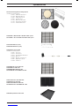
This manual covers a range of barbecues which include: Graphite,
Elite, Elite Plus, Supreme, Supreme Plus, Deluxe, Deluxe Plus,
Grande, Super Grande and Rear Burner Models.

2
559802 - Masport 4/6 Burner 210 Series - May 2015
Keep the instructions in a safe place for future use.
Do not operate this BBQ before it has been
assembled correctly and you have read and
understood these instructions.
These instructions are intended as a general
guide and do not supersede national or local
codes in any way. Contact local Authorities for
clarity of laws relating to the operation of this
appliance.
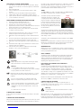
Symbols in this Owner’s Manual
Possible hazard or hazardous situation.
Not observing this instruction can lead to injuries or
cause damage to property.
Important information on proper handling.
Not observing this instruction can lead to faults in the
BBQ.
User information. This information helps you to use all
the functions correctly.
Failure to follow these instructions could result in fire or
explosion which could cause property damage, personal
injury or death.
Accessible parts may be very hot. Keep young children away
from the hot appliance at all times (even while cooling down).
Some parts of this grill may have sharp edges especially as
mentioned in this manual! Wear suitable protective gloves if
necessary.
Assembled parts sealed by the manufacturer must not be
altered by the user. Any modification of the appliance by
unauthorised persons may be dangerous.
Important Safety Information
Please read and understand this manual fully before assembly and
use.
• The Manufacturer’s Warranty may be voided by the incorrect use
of this product.
• The Manufacturer or their Agents can accept no liability for the
unsuitability of, or any damage to, food that is cooked on this
appliance.
• Use the correctly specified fuel with this barbecue. Check with
your dealer for the specific fuel for which this barbecue has been
designed.
Owner’s Manual
• The operator must understand all the safety requirements detailed
in this manual before using the barbecue.
• If you have any queries regarding these instructions, contact your
local dealer for clarification before you use your barbecue.
• The unit must be correctly assembled before use. Failure to follow
the manual’s instructions could result in serious damage or injury.
Personal Safety
• The use of alcohol, prescription or non-prescription drugs may
impair the consumer’s ability to properly assemble or safely
operate this barbecue.
• The barbecue should be carefully checked for operational use
every time before use.
• Never try to move the barbecue when it is on, or before it has had
time to cool down.
• The person operating this barbecue should pay constant attention
to the food being cooked.
• Do not leave the barbecue unattended when it is alight. The
person should remain at the barbecue at all times when it is
alight/cooking.
Third party safety
• The operator is responsible for the safety of all third parties while
the barbecue is in use.
• Onlookers should be kept a safe distance away from the
barbecue when it is in use.
• Keep children and animals well away while the barbecue is in use
and while it is cooling down.
Safety and Warranty Information 2-3
Assembly instructions 5-15
Leak Testing 16
Location Information 16-17
Lighting Instructions (Operation) 17-18
Rear Burner, Timer, and Accessories 18-20
Troubleshooting 20
Parts 21-23
Optional Extras 24
Care & Maintenance 25-27
Technical Data 28-30
Contents

3
559802 - Masport 4/6 Burner 210 Series - May 2015
Location
• Do not use indoors. Barbecue units are designed for OUTDOOR
USE ONLY.
• Use in a weather-protected area, preferably under shelter.
• Ensure that the barbecue is on an even and secure surface before
operating. Use the castor locks if fitted to lock the wheels in
place.
• Do not use within one metre of any flammable surface of
structure.
Burn awareness
• Parts of the barbecue do get extremely hot and could cause
serious burns – touch test the surface before applying a firm grip.
• The hood handle can become hot! The use of cooking gloves and
long sleeves are advised.
• If cooking with the hood closed, be very careful opening the hood,
a sudden rush of hot air could burn an unprotected arm.
Gas awareness
• Ensure all gas couplings and hoses are in good condition and
have been correctly fitted.
• Leak test all gas lines and connections before use.
• Do not store flammable materials near this barbecue.
• Do not place the gas bottle underneath the barbecue directly.
• Do not store spare LPG cylinders under or near this barbecue.
• Do not place or use aerosols near this barbecue.
• Do not store or use gasoline or other flammable vapours or liquids
in the vicinity of this barbecue.
• Ensure that the gas is turned OFF at the cylinder after use and
while the barbecue is unattended.
• When turning off the barbecue, shut off the gas at the supply
source before turning off all the burner controls.
• Do not store gas cylinders below ground level. ULPG is heavier
than air. Should a leak occur, the gas will collect and could ignite
due to presence of a flame or electric spark.
For your safety and others
If you smell gas:
Shut off the gas supply to the barbecue.
Extinguish any open flame (candles, cigarettes, etc.)
Clear the area to allow the unburned gas to dissipate.
Be aware of the reason for the gas smell, address this before
continuing. Should the gas odour come from the LPG cylinder,
immediately contact the fire department from an elevated safe
distance.
Connecting the gas cylinder to the barbecue, refer to that section in
the manual.
Leak testing, refer to that section in the manual.
Safety Equipment
When cooking with oil/grease, fire extinguishing materials should be
readily accessible.
In the event of an oil/grease fire do not attempt to extinguish with
water or alcohol. Use type BC dry chemical fire extinguisher or
smother the fire with dirt, sand or baking soda.
Rain Hazard
In the event of rain while cooking with oil/grease, turn off the gas
supply and all burners, cover the barbecue as soon as possible.
Move people/animals away from around the barbecue. Do not
attempt to move the barbecue until it has cooled and can safely be
moved.
Installation
This Cooking Appliance is For Outdoor Use Only and
shall not be used in a building, garage or any other enclosed
area.
Note!
Read carefully the pages containing the parts and
assembly before assembling your gas grill.
The location for your grill
Do not use your gas grill in garages, porches, breezeways, sheds
or other enclosed areas. Your gas grill is to be used outdoor only, at
least 43cm from the back and side to any combustible surface. The
grill should not be placed under any surface that will burn. Do not
obstruct the flow of combustion and ventilation air around the grill
housing. Keep this barbecue away from any flammable materials!
(Refer to page 16)
Gas and Regulator Information
Gas grills are used safely by millions of people when following
simple safety precautions. This barbecue is designed for ULPG
use only. Bottle size of 4.5kg or greater is recommended for use
with this barbecue. The regulator must have an outlet pressure of
2.75kPa. You must have the correct regulator and bottle for the
barbecue to operate safely and efficiently. The items used in the fuel
system are designed for operation with the grill. (See parts list for
replacement items).
Natural Gas conversion option - refer to page 15
Warranty
Refer to the warranty supplied with this BBQ. Should any part fail
due to defective workmanship or faulty materials within the specified
period from the date of purchase, Masport will replace or repair the
defective part free of charge. Refer to the warranty for details. Do
not use a BBQ that is unsafe.
LPG cylinder
The cylinder manufacturer/distributor is responsible for the safety
and performance of the LPG cylinder. This is not included in the
Masport BBQ warranty. Do not use a cylinder that is unsafe.
Disposal of Packaging
Remove all protective packaging including any protective film from
stainless steel surfaces.
Make sure you properly dispose of, or recycle the packaging
material where possible to comply with applicable waste disposal
laws in your area.


5
559802 - Masport 4/6 Burner 210 Series - May 2015
Assembly Instructions
Product Description
Carton Identification
Product Part Number
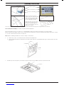
Open the carton by removing the
shipping straps then slitting along both
ends. Cut the tape only by a small
amount in the middle, finish by lifting
the carton flaps with your hand.
Unpack the entire carton, this carton
will be used as a surface protector as
the cabinet is being built. Open the
carton as shown and place where the
BBQ will be assembled
Note: Letters in the bracket after every screw, helps you identify the item number from the parts list on page 6, from the fastener kit.
Tools needed for assembly: Crosshead screwdriver, 10mm A/F Spanner
Open the fastener kit, place to one side, 4 pcs screw (SS) M6x12 (item b) & 4pcs fibre washer (item c) for Hood Assembly.
Before commencing assembly, open the cartons and lay all of the components on the floor. Familarise them against the parts list on page
21, as some of these instructions refer to this parts list.
Note: When assembling the barbecue, ensure it is sitting on a flat surface.
1. 1) Remove the screws , nuts and the washers fastened to the Weight Plate.
2) Fix the weight Plate (item 32) under the base tray (item 1) with these 2pcs Screw M6*40 (item g) 2pcs washer, (item h) 2pcs Nut
M6 (item f).
1
Screw M6*40
32
Washer
Nut M6
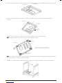
2. Assemble 1pc Front skirt (item 2) to the Base tray (item 1) using 2pcs Screw M6×12 (item a) from the fastener kit.
2
Screw M6*12

6
559802 - Masport 4/6 Burner 210 Series - May 2015
3. Assemble 1pc Left skirt (item 3) to the Base tray using 3pcs Screw M6×12 (item a) and 1pc Screw M5*10 (item d) from the fastener kit.
3
Screw M6*12 Screw M5*10
4. Assemble 1pc Right skirt (item 4) to the Base tray using 3pcs Screw M6×12 (item a) and 1pc Screw M5*10 (item d) from the
fastener kit.
Screw M5*10 4
Screw M6*12
Rear of the
barbecue
5. Assemble 4pcs Castors (item 5) to the Base tray using 16pcs Screw M6×12 (item a) from the fastener kit.
Assemble the casters and lock the rear castors before assembling the cabinet
Screw M6*12
5
Lock this castor
Locking the rear castors will steady the base.
Position the base with the locks facing outwards.
Lock this
castor
Front of the
barbecue
Here on going forward keep the screws loose until the cabinet structure is complete. This will greatly assist with positioning the
panels. Tighten all screws when cabinet is assembled.
6. Assemble the Left panel (item 6) and Right panel (item 7) to the Base tray using 4pcs Screw M6×12 (item a) from the fastener kit.
M6*12
7
6
Screw M6*12

7
559802 - Masport 4/6 Burner 210 Series - May 2015
7. Assemble the Back panel (item 8) using 5pcs Screw M6×12 (item a) from the fastener kit.
M6*12 8
Screw M6*12
Front of the barbecue
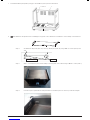
8. Assemble the side panels before assembling the top panel on the cabinet then assemble this sub-assembly on the barbecue.
Step 1. Assemble the side panels (item 37) to the top cabinet panel (item 36) using 3 xM6 x12 screws (item a) each
side.
Side
Panels
Top Cabinet
Panel
Top Cabinet Panel Side Panel
Step 2. Step 2 – Assemble this panel sub assembly to the rear panel of the cabinet using 3 xM6 x12 screws (item a).
Step 3. Insert the top front panel with the side panel extension inside the panel as shown to provide the strength.

8
559802 - Masport 4/6 Burner 210 Series - May 2015
Step 4. Assemble the door panel to the side panels of the cabinet using 2 xM6 x12 (item a) screws each side. Keep
the screws loose.
Door Panel
Side Panel
Cabinent
Step 5. Assemble the door panel and the top cabinet panel using 4 xM6 x12 screws (item a). Keep the screws loose.
Step 6. Once all the parts mentioned above are assembled tighten all the screws.
9. Assemble Left door (item 10) and Right door (item 11) using 4pcs Screw M6×12 (item a), 4 Handle brackets (item 12) and 2 Handles
(item 13), then assemble the door assemblies as the picture.
Note!
Once the cabinet has been fully assembled, and
the doors open and close correctly with even
clearances top and bottom, and side to side, the
screws can now be fully tightened.
Note!
To keep screw slot against screwdriver pass screw
through ribbon of plastic, hold both together,
assemble screw to handle, remove plastic, and re-
use for other three screws.
M6*12
Screw M6*12
11
13
12
10

9
559802 - Masport 4/6 Burner 210 Series - May 2015
PREPARING THE HOOD / GRILL ASSEMBLY
Open the hood carton and remove the warming rack (item 23)
Lift up and out the polystyrene corner packing.
Remove the protective layer from the hood.
Cut open all sides with a knife taking care not to damage the hood or grill in the process.
Open the carton walls outwards and flatten. Remove the polystyrene packing from beneath the grill.
Open the hood and remove in order:
• Packed cartons (some are empty and used as a gap filler) and any polystyrene packaging
• Grill first, then hotplate
• Remove the layer of cardboard
• Remove extra feature options if any. Some specific barbecue models include some extra feature items.
• At the rear you will locate the drip tray (item 18) remove this, (it is packed in the reverse). This may require the removal of the 2x step
Screws (item e)
• The Hood / Grill is now ready to be lifted onto the cabinet. This is a large and heavy assembly which requires two persons to lift it
safely into position.
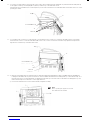
10. 1) Assemble the hood and grill assembly (item 14) to the cabinet trolley with 4pcs Screw (SS) M6*12 (item b) and 4pcs fibre washer
(item c) from the fastener kit.
2) In some barbecue models the knobs are not fitted to the grill then assemble 6 pcs knob (item 15) to the valve shaft on the body
assembly, as per the illusration below.
3) If the rear burner knob is not fitted to the grill assemble 1 x knob - Rear burner (item 34) to the Rear burner valve shaft.
When the Timer is OFF the flat on the
shaft faces the Bottom / 6 o’clock
position and the Flat on the knob
insert should match this position.
When the Timer is OFF the rounded shaft contour faces the
Top/ 12 o’clock position and the flat spring metal insert grips
the round face of the shaft of valve.
Screw SS M6*12
Big fibre washer
14
Screw SS M6*12
Big fibre washer
14
15

10
559802 - Masport 4/6 Burner 210 Series - May 2015
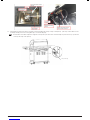
11. Loosen the 3 Screws (item b), remove the 4th & 5th screws, then assemble the heat shield (item 33) and left hand side shelf (item 16)
to the appliance with 5pcs Screw (SS) M6*12 (item b). Level the top of the table and secure.
If the timer knob is not fitted then, fit one knob (item 15) on the shaft of the timer on the side table. Refer to the timer section for correct
operating procedure.
15
Screw SS M6*12 (b)
16 (b)
33
4th & 5th
12. Loosen fully but do not remove 4 screws (item b) as shown. Remove two screws 5 & 6, lower the side table over the screw heads.
Fasten the four screws to secure the side table. Refit screws 5 & 6, screw 6 secures the facia which may require frontal pressure to
align this hole. Level the top of the table and secure.
15
Screw SS M6*12 (b)
16 (b)
33
4th & 5th
13. 1) Remove all packaging from the side burner prior to fitting the Right Hand (side Burner) table to the BBQ. Prepare the BBQ prior
to fitting the side table, refer to previous instructions. Then assemble the Side burner assembly (item 17) as described in step 13. If
the knob (item 15) has not been fitted then assemble the knob (item 15) to the valve shaft on side burner assembly (item 17), and
make sure the red point on the knob is on the upper direction.
2) Connect the side burner hose to the main manifold, and tighten carefully.
Note!
Before operating this appliance for the first
time LEAK TEST ALL JOINTS.

11
559802 - Masport 4/6 Burner 210 Series - May 2015
14. Put the Drip tray (item 18), Grease cup (item 19) into the grill body and 2pcs Step screw (item e) - (the step screws will be on the
assembly already) to the rear of the grill body to secure the drip tray.
Some barbecue models require the stepped screws (item e) are removed to insert the drip tray. Once the tray is positioned
correctly, refit step screw (item e).
18
19
Step screw (e)

12
559802 - Masport 4/6 Burner 210 Series - May 2015
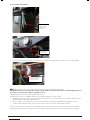
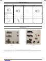
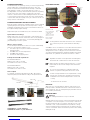
15. Connecting the ignition wire/ wires to the electronic module
Note:
1) The rear burner valves operate with the electronic ignition.
2) All the side burner valves operate with the integrated ignition.
Check the diagram of module to determine the BBQ ignition type
1) If the module has only one pin i.e. connecting single wire then Rear burner operates with electronic ignition
2) If the module has multiple pins for connecting the wires then Rear burner and Main burners operate with electronic
ignition.
Single Pin Electronic module 4 Pin Electronic module 6 Pin Electronic module 7 Pin Electronic module
Ignition module attached on
the Right side Table
Follow the diagram to connect the wires between the electronic module and the electrode.
Connect the lead wire with the electronic ignition as shown below. Make sure that the wire is clipped tight.
Single Pin Electronic Module:
Connect the lead wire with
the electronic ignition, no
sequence is required,
Connect the lead wire with
the electronic ignition, no
sequence is required,

13
559802 - Masport 4/6 Burner 210 Series - May 2015
4 / 6 / 7 Pin Electronic Module:
1.
Total 7 pcs of the
lead wire for all
main burners and
rear burner.
2.
The assembled
position of the
electronic ignition
The assembled
position of the
electronic ignition
3. Connect the lead wire with the ignition as shown below, no sequence is required, make sure that the wire is securely clipped.
Connect the lead wire with
the electronic ignition, no
sequence is required,
Make sure that the wires are securely positioned on each end and routed through the wire clips.
The BBQ body works as an earth for the electronic module. Make sure that the side table is assembled tightly and forms
the complete circuit. If not, the ignition spark will not occur.
CAUTION: All wires must be properly routed through wire clips.
Verify the ignition system of your BBQ model before connecting the regulator to the gas cylinder
1) Integrated ignition valve - Push in then turn the knob anticlockwise to HI. Test each burner to hear a clicking sound with spark. It
indicates the valve is fitted with integrated ignition.
2) Electronic ignition - Install the battery in the electronic module fitted on the RH side table. Make sure the battery is in good
condition and the battery polarity is correct. Push the button to hear a continuous clicking sound with spark.
Listen & look for the sparks at all the burners’ individually and make sure that all the valves are functioning smooth by turning them
“ON” (by pushing the control knob in and turning anticlockwise) and “OFF” (by pushing the control knob in and turning clockwise).
Connect the lead wire with
the electronic module, no
sequence is required.

14
559802 - Masport 4/6 Burner 210 Series - May 2015
Inserting/Changing the Battery
Unscrew the pulse cap assembly. Insert the battery as shown. Replace the pulse cap assembly. For single pin modules 1 X AAA battery is
required for the replacement, and for 4 / 6 / 7 pin modules 1 X AA battery is required for the replacement.
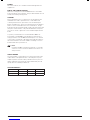
16. Place the Flame tamer (20) to the positions as in the pictures.
4 BURNER BBQS
20
6 BURNER BBQS
20
RB BURNER BBQS
20
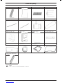
17. Place the Cooking grill (21), Cooking plate (22), Deep dish (35 - only if applicable) and Warming rack (23) to the frame body as in the
diagrams.
Note! The cooking plate and deep dish must not be used at the same time. The barbecue is designed to operate safely
with approx 34% of the cooking surface being on an open grill.
21 22
23
21 22
23
21
23
35

15
559802 - Masport 4/6 Burner 210 Series - May 2015
Inserting/Changing the Battery
Unscrew the pulse cap assembly. Insert the battery as shown. Replace the pulse cap assembly. For single pin modules 1 X AAA battery is
required for the replacement, and for 4 / 6 / 7 pin modules 1 X AA battery is required for the replacement.
16. Place the Flame tamer (20) to the positions as in the pictures.
4 BURNER BBQS
20
6 BURNER BBQS
20
RB BURNER BBQS
20
17. Place the Cooking grill (21), Cooking plate (22), Deep dish (35 - only if applicable) and Warming rack (23) to the frame body as in the
diagrams.
Note! The cooking plate and deep dish must not be used at the same time. The barbecue is designed to operate safely
with approx 34% of the cooking surface being on an open grill.
21 22
23
21 22
23
21
23
35
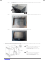
For Models With Rotisserie - Assembly Instructions
Tools needed for assembly
Crosshead screwdriver, 10mm A/F spanner, 2x 8mm A/F Spanners.
18. Assemble the Prong (24), the Rod-A (25), the Rod-B (26) and the Guide (27), the Rotisserie handle (28) together as in the diagram.
Note!
Rotisserie Rod 26 is threaded LH, assemble by turning rod anti-clockwise. Tighten with 8mm A/F Spanners. This connection must
remain spanner tight.
25 24 26
27 28
Place inside of grill
Assemble the Motor holder (29) to the appliance with 2pcs Screw M6*10 (a), 2 fibre washer (c) and 2pcs Nut M6 (f) as the
diagram. Place the battery (31) into the Motor (30). Assemble the Motor and Rotisserie to the appliance as the picture.
Note!
Take note of the battery + - positions prior to fitting the batteries.
Note! There is an option to use a mains adaptor (not stocked). Requires:
Mains adaptor 240 volt > 3 volt DC 3 milliamps or greater.
Rotisserie
Nut M6
Fibre washer Screw M6*12
29
30
Note!
For 210 models without a Rotisserie, there is an option to purchase 559218 Rotisserie Set-210.
Natural Gas Conversion
The 210 Series of BBQ has the option of being converted to natural gas. This conversion must be actioned by a certified agent using a
Masport NG conversion kit.
The certifying agent (usually a gas fitter or gas plumber) will update the information on the data plate to keep the barbecue compliant with
local regulations.

16
559802 - Masport 4/6 Burner 210 Series - May 2015
Leak Testing
When to Test: The BBQ gas bottle, regulator & hose assembly
should be checked for leaks, using the soapy water leak test, every
time you reconnect your regulator to the BBQ gas bottle. You
should also test after any long period of non-use, such as at the
beginning of BBQ season.
What to use: You will need a soapy water solution to check for any
leaks. Mixing liquid hand soap with water will work fine (do not use
any other household cleaning products).
How to Test: Put some soapy water in a spray bottle or a dish.
Turn on the gas bottle but do not turn on the BBQ. Next, spray
the entire valve, regulator and hose assembly with the soapy water
including where the hose connects to the BBQ. Alternatively, you
can apply the soapy water with a paint brush, basting brush.
Bubbles will form if there is a gas leak and you may also smell the
gas. If you find a leak, turn off the gas bottle immediately!
Do not turn back on or attempt to use the BBQ if a gas leak has
been detected, contact your local BBQ Dealer for repair.
Installation
This barbecue is for outdoor use only and should be placed in
a well-ventilated area. Take care to ensure that the minimum
clearances guidelines are followed:
Minimum clearances:
From sides: 430mm; From back: 430mm
From above (vertical): 1000mm
Keep this barbecue away from any flammable materials! This
appliance shall only be used in an above ground open-air situation
with natural ventilation, without stagnant areas, where gas leakage
and products of combustion are rapidly dispersed by wind and
natural convection. This barbecue is not designed for marine use.
Any enclosure in which the appliance is used shall comply with one
of the following:
1. An enclosure with walls on all sides, but at least one permanent
opening at ground level and no overhead cover.
2. Within a partial enclosure that includes an overhead cover and
no more than two walls.
3. Within a partial enclosure that includes an overhead cover and
more than two walls, the following shall apply:
a) at least 25% of the total wall area is completely
open and unrestricted
b) at least 30% of the remaining wall area is open
and unrestricted
4. In the case of balconies, at least 20% of the total of the side,
back and front wall areas shall be and remain open and
unrestricted.
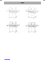
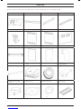
See following diagrams for further illustration:
FIGURE F1-OUTDOOR AREA-EXAMPLE 1
FIGURE F2-OUTDOOR AREA-EXAMPLE 2
Both ends open
FIGURE F5-OUTDOOR AREA-EXAMPLE 5
FIGURE F3-OUTDOOR AREA-EXAMPLE 3
FIGURE F4-OUTDOOR AREA-EXAMPLE 4
Open side at
least 25% of total
wall area
30 percent or more in total
of the remaining wall area is
open and unrestricted
Open side at
least 25% of total
wall area 30 percent or more in total
of the remaining wall area is
open and unrestricted

17
559802 - Masport 4/6 Burner 210 Series - May 2015
OTHER PRECAUTIONS
Do not obstruct any of the ventilation openings in the barbecue
body. Also, position the gas supply cylinder inside the cabinet, in
the cylinder base positioning hole. Should you need to change
the gas cylinder, confirm that the cylinder is off, and that there are
no sources of ignition (cigarettes, open flame, sparks, etc.) near
before proceeding. Be sure to inspect the gas hose and ensure it
is free of any twisting or tension. The hose should hang freely with
no bends, folds, or kinks, which could obstruct free flow of gas.
Apart from the connection point, no part of the hose should touch
any hot barbecue parts. Inspect the hose before use. If the hose
is damaged, it must be replaced with a hose suitable for use with
ULPG and meet the national standards for the country of use. The
length shall not exceed 1.5m. Should minimum clearances not
be adhered to severe flare up may be experienced due to lack of
airflow around the barbecue, thus voiding manufacturer’s warranty.
GAS AND REGULATOR INFORMATION
This barbecue is designed for LP gas use only. Bottle sizes of 4.5kg
or greater are recommended for use with this barbecue. Suitable
LPG regulators must have an outlet pressure of 2.75 kPa. You must
have the proper regulator and bottle in order for the barbecue to
operate safely and efficiently. Please consult your local gas dealer
for the most suitable gas cylinders. Please note the regulator
supplied with this barbecue is of an approved type.
The manifold thread type is 5/8” x 18.
For more information on pipe sizing, please refer to AS/NZS 5601 /
AG601 for details.
The gas cylinder must always be stored or used in an upright
position.
Gas Cylinder
Bleeder Valve Screw
Gas Shutoff Valve
Tighten in this direction
POL regulator
and hose
Protector Cap
FIXING THE POL GAS REGULATOR TO THE CYLINDER
Confirm all barbecue control knobs are in the off position.
Hand-tighten the regulator supplied with this barbecue to the gas
cylinder by screwing in an anti-clockwise direction.
DO NOT OVERTIGHTEN!
As the regulator is fitted with a soft nose, it should only be tightened
a further 1/4 turn after resistance is first felt.
Operation
Warning!
Before proceeding, be certain you understand the safety
information contained in this manual.
This barbecue is not designed to be used with more
than 66% of the cooking area as a solid plate. Full
coverage of plates will cause excessive build-up of
heat and damage the barbecue.
Note!
Before using the barbecue for the first time, the barbecue
must be lit and burning for 30 minutes on the “low” setting.
Important!
The regulator supplied with this BBQ may incorporate
an Excess Flow Control Safety Device. The Excess Flow
Control will activate to prevent gas flow should a regulator
malfunction occur. It is important that the BBQ operator
understands that all gas valves on the BBQ are closed in
the OFF position prior to opening the gas cylinder valve.
If the BBQ valves are open prior to opening the cylinder
valve, the Excess Flow Control will be activated and
prevent the BBQ from being lit. To reset, close the BBQ
valves and gas cylinder valve, wait for 1 minute and use
correct lighting procedure as detailed below.
MAIN BURNER AND SIDE BURNER LIGHTING
(INTEGRATED IGNITION)
1. Open the lid before igniting the barbecue
2. Check all the knobs are in the “OFF” position
3. Open the gas control valve at the gas cylinder
4. The valves fitted to this BBQ include a safety feature. The
valve must be depressed before turning. This feature prevents
accidental activation of the knob
5. From the “OFF” position, push in then turn control knob anti-
clockwise to the “HI” position until hear a “click” sound
6. Repeat step 4, 3-4 times until the burner is lit
7. If the burner fails to light, turn off and wait for 5 minutes, then
begin from step 4
8. Once a burner is lit, similarly light the remaining burners.
9. Turn the knob anticlockwise to adjust the heat from High –
medium – Low to your heat requirement.
MAIN BURNER LIGHTING (ELECTRONIC IGNITION)
1. Open the lid before igniting the barbecue
2. Check all the knobs are in the “OFF” position
3. Open the gas control valve at the gas cylinder
4. Operate each valve in combination with the electronic ignition
push button on the side burner table
5. From the “OFF” position, push in then turn control knob anti-
clockwise to the “HI” position
6. Keep the knob pushed-in at the “HI” position for 4 seconds
whilst pressing the electronic ignition push button
7. Repeat step 4, 3-4 times until the burner is lit
8. If the burner fails to light, turn off and wait for 5 minutes, then
begin from step 4
9. Turn the knob anticlockwise to adjust the heat from High –
medium – Low to your heat requirement.
FOR MANUAL IGNITION (MAIN BURNER)
1. Light a 90mm barbecue match and hold adjacent to the lighter
hole at the right end of the barbecue. (Fig.1)
2. Turn the right hand gas control knob to the high position. The
burner will light from the match.
3. Once the right burner is lit, the burner next to it can be turned
on and will light off the lit burner. Repeat until all burners are
alight.
4. Each burner can be adjusted. Turn the knob anticlockwise
to adjust the heat from High - medium - Low to your heat
requirement.
MANUAL IGNITION:
Light here with a
90mm match or
lighting gun

18
559802 - Masport 4/6 Burner 210 Series - May 2015
FOR MANUAL LIGHTING (SIDE BURNER)
1. Turn all knobs to “OFF” then open the LP tank valve. Always
keep your face and body as far from the grill as possible when
lighting.
2. Raise side burner lid.
3. Push in and then turn control knob anticlockwise to high
position.
4. Place a lit match near the burner until the burner ignites.
5. If burner fails to light, turn off and wait 5 minutes, then try
6. again. If burner still does not light after repeated attempts, call
7. your local dealer for assistance.
REAR BURNER LIGHTING (ELECTRONIC IGNITION)
1. Open the lid before igniting the barbecue
2. Check all the knobs are in the “OFF” position
3. Open the gas control valve at the gas cylinder
4. Operate the rear burner valve in combination with the electronic
ignition push button on the side burner table
5. From the “OFF” position, push in then turn control knob anti-
clockwise to the “HI” position
6. Keep the knob pushed-in at the “HI” position for 4 seconds
whilst pressing the electronic ignition push button
7. Repeat the steps from beginning, 3-4 times until the burner is
lit
8. Once the rear burner has ignited keep the knob pushed-in at
the “HI” position until the rear burner ceramic glows red
9. Repeat the steps from beginning, 3-4 times until the burner is
lit
10. If the burner fails to light, turn off and wait for 5 minutes, then
repeat the steps from beginning
11. Turn the knob anticlockwise to adjust the heat from High –
medium – Low to your heat requirement.
Important!
Keep a spray bottle of soapy water near the gas supply
valve and check the connections before each use.
Warning!
1. Do not light the grill if odour of gas is present.
2. It is important to ensure that all control valves, including
the gas cylinder, are turned off after use.
When using the rear burner and rotisserie use 1 or 2 of the
main burners at the low heat setting if a little extra heat is
required.
Do not use the rear burner in combination with main
burners on high heat setting when the hood is closed.
Caution / Danger: Extreme care is required when cooking
with hood in closed position. Frequent checks must be
undertaken for the heat and temperature to ensure safe
cooking.
Too much heat can cause fire.
TURNING OFF A BURNER
Push in then turn each burner control knob clockwise to the “OFF”
position.
TURNING OFF YOUR BARBECUE
When you have finished using your barbecue, turn off the gas at the
bottle. Push in and then turn all the control valves fully clockwise to
the “OFF” position. Wait until the barbecue is sufficiently cool before
replacing the barbecue lid or closing its hood. Once cooled, a
protective cover should always be fitted to the barbecue to protect
your investment from the ailments when not in use.
TIMER
The BBQ TIMER is located on the Side Table. The TIMER will give
an audible sound when a pre-set time is activated.
The Timer is purely a mechanical device
worked by an internal coil spring. The
coil spring works both the timer and the
ringer and requires adequate winding up
to work correctly. If setting for a period of
less than sixty minutes the timer should
first be wound clockwise half a turn to
the sixty minute graduation, then back to
the desired time.
The timer has a maximum setting of 120 minutes with graduation
markings at 5 minutes intervals. The timer is purely a time indicator
and should not be used for accurate time measurement. DO NOT
leave the BBQ unattended when cooking, plus frequently check the
items being cooked.
The below actions will damage the internal workings of the TIMER
beyond repair.
DO NOT force the timer knob clockwise more than one full turn and
DO NOT force the timer knob anti-clockwise past the 120 minute
“top” graduation mark as this will damage the timer.
WARMING RACK
Warming racks are a convenient way to keep cooked food warm or
to warm items such as bread rolls. Always check that your warming
rack is properly fitted before use.
GRILL COOKING
The burners heat up the flame tamers underneath the grill, which
in turn heats the food on the grill. The natural juices produced
during cooking fall onto the flame tamers below and vaporise. The
subsequent rising smoke bastes the food, as it travels upwards,
imparting that unique barbecue flavour.
FLAT PLATE / FLAT-RIBBED PLATE / DEEP DISH
(where supplied)
The burners heat the griddle plate directly, which then cooks the
food on contact. These allow for the cooking of smaller items, such
as seafood, which could fall through the spaces of a grill. They
are also suitable for cooking items that require high-temperature/
short-duration cooking, such as vegetables and smaller cuts of fish.
Similarly, these can be used in exactly the same way as a griddle in
the kitchen, for searing steaks, cooking eggs, etc.
DO NOT use both the plate and deep dish at the same time. This
will cause your BBQ to overheat and could cause a fire.
COOKING AND USE OF HOOD
Barbecues equipped with a roasting hood give the option of
cooking with hood closed to form an ‘oven’ for roasting food, such
as joints of meat, whole chickens, etc.
Warning!
Cooking with the hood closed and the burners on high
creates a fire risk.
When the hood is closed, a large amount of heat is trapped inside
the barbecue. Thus, it is IMPORTANT to make sure that all the
burners are turned to the low position to prevent burning of the food
and damaging the barbecue. Avoid lifting the hood unnecessarily
Clockwise

19
559802 - Masport 4/6 Burner 210 Series - May 2015
as heat is lost every time the hood is opened. Use the temperature
gauge to check the heat of the barbecue. DO NOT ALLOW YOUR
BARBECUE TO OVERHEAT. A BARBECUE SHOULD NEVER BE
LEFT UNATTENDED WHILE COOKING!
For safety reasons, barbecue plates and grills will not cook as hot
towards the front of the barbecue.
FRONT
The slightly lower temperature at the front can easily be overcome
by rotating the food being cooked around the barbecue plate or
grill.
FLARE-UP CONTROL
Flare-ups occur when meat is barbecued, and its fats and juices
fall upon the flame tamers. The smoke from some flare-up helps
give cooked meat its barbecued flavour, but excessive flare-up will
result in meat being burned. To control flare-up, it is advisable to
trim away excess fat from meat and poultry before grilling. Also, the
burners should always be placed on the low setting during cooking.
Finally, extinguish flare-ups by applying baking soda or salt directly
onto the flame tamers. Always protect your hands when handling
anything near the cooking surface of the barbecue.
If a fat fire should occur in the drip tray, turn all knobs to the off
position, turn off the gas at the bottle, and wait for the fire to go out.
Do not pull out the drip tray or douse with water.
COOKING USING OPTIONAL ACCESSORIES
Rotisserie Cooking (Optional)
1. Carefully remove the cast iron cooking surfaces and the
warming rack from the barbecue.
2. Place the flame tamers to the centre of the barbecue body. It is
over this area that the meat will be cooked.
3. Slide one of the spit forks onto the spit rod and tighten its
thumb screw to secure it into place. Insert the pointed end of
the spit rod into the meat being cooked and slide the meat
towards the centre of the rod. Make sure the fork is fully into
the meat. Slide the other fork onto the rod, into the meat, and
tighten the thumb screw once in place. For optimal rotisserie
cooking, food must be placed securely onto the middle of the
spit rod and balanced so that the rotisserie can rotate freely
without interference from any barbecue surfaces. Any loose
sections of meat should be secured so they do not hang down
and interfere with the rotation of the spit rod.
4. Insert the pointed end of the spit rod into the motor. Lay the
other end of the spit rod onto the opposite bracket.
5. Light the barbecue.
6. Turn on the rotisserie motor to begin rotisserie cooking. The
hood has been designed so that it may be closed during
rotisserie cooking.
7. Always cook foods on the lowest flame setting to avoid burning
or overcooking.
8. DO NOT ALLOW YOUR BARBECUE TO OVERHEAT. A
BARBECUE SHOULD NEVER BE LEFT UNATTENDED WHILE
COOKING!
9. If cooking with rotisserie using indirect heat (not using burners
directly under meat - oven style cooking), a baking dish (not
supplied on some models) can be placed under the food to
catch fats and drippings.
Infrared Rear Burner & Rotisserie (Optional)
Preparing your barbecue:
You will need to remove both grill plate and solid plate, also
the
flame tamers and warming rack. Place these in a safe place
for later
re-assembly. Place a baking dish (not supplied) onto the burners,
the dish should be large and deep enough to capture the excess
grease as it falls from the food.
Centrally secure the food with the rotisserie prongs, turning the
rotisserie rod by hand to test for balance, adjust the food position
if required. Insert pointed end of rod into the motor, test that
everything is running correctly.
Using the Rear Burner for roasting on a barbecue can be different
depending on our preferences. A suggestion might be to use 1-3
of the main burners to cook the roast and then use the Rear Burner
towards the end of the cooking to “brown up” the roast. Using
the Rear Burner by itself to do the cooking can take a long time
depending on the size of the roast.
Do not use the rear burner in combination with main
burners on high heat setting when the hood is closed.
Caution / Danger: Extreme care is required when cooking
with hood in closed position. Frequent checks must be
undertaken for the heat and temperature to ensure safe
cooking.
Too much heat can cause fire.
Interchangeable Cooking System (Optional)
Preparing your barbecue for pizza cooking:
Remove the round grill or plate insert.
Season the pizza stone with olive oil. Place the stone into a cold
oven or cold BBQ and slowly raise the temperature to 180°C for 20
minutes.
Do not place a cold pizza stone into a hot environment. This
could cause the stone to break due to uneven
temperatures.
Do not wash the pizza stone with any cleaning agent. Brush
any crumbs off the surface, do not gouge or cut into the
surface during cleaning.
Do not remove the flame tamers from the BBQ. These
should be positioned under the pizza stone.
Do not use the pizza stone as a cutting table.
Do pre-heat the BBQ to around 200°C - 245°C prior to
cooking the pizza.
Do sprinkle a little flour or cornmeal to stop the pizza
sticking to the stone.
Do keep fillings away from the pizza edge, food spills may
spoil the pizza stone.
Do transfer your pizzas to the stone with a pizza paddle (not
supplied). Remove the pizza from the stone to the table/
board for cutting.
Do lower the burners directly under the stone, this will allow
the pizza to cook more evenly.
Do check after 10 minutes by raising the hood slightly, be
aware of a possible heat rush coming from within as you lift
the hood.
Do not remove the pizza stone from the BBQ with oven
mitts directly after cooking. The pizza stone reaches a very
high temperature, wait for the pizza stone to cool naturally.
Do lightly oil the pizza stone after each cooking session.

20
559802 - Masport 4/6 Burner 210 Series - May 2015
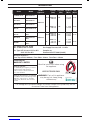
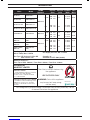
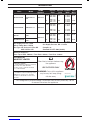
Checklist
Problems Possible Cause Solutions
Burner won’t light after pushing and turning the
knobs
Electrode deposited with cooking residue Use clean swab and alcohol to clean
Electrode damaged Replace
Electrode wires are loose or discounted Reconnect or replace with new Electrode assembly
with wires
Orifice blocked Check the orifice for blockage
Wire is shorting Ensure connections are tight
Replace with new Electrode assembly with wires
Burner can’t light by match No gas Open the LP tank valve
Gas flow is not smooth Clear burner tubes
Incorrect assembly between burner and valve Re-assemble
Yellow or orange flames, with gas odour Incomplete combustion 1. Check the burner inlet for obstruction such as
spiders
2. Check air shutter for correct adjustment
3. Check for the source
Low heat with knob in “high” position Gas hose bent or kinked Straighten
Burner or orifice blocked Clear
Low gas pressure Check Cylinder/ Regulator (refer to pg. 15)
Grill not preheated Preheat the grill for 15 minutes
Flare up Excessive meat fat Cut off fat before grilling
Over high temperature Adjust
Grease deposit Clean
Flame out Over high winds Find a less windy place
Flame lifting Over high gas pressure Call the gas dealer
Flashback Burner port blocked Clean
Grease fire Grease accumulated in food Turn off knobs, LP tank valve, leave lid open, let fire
burn out. Clean the grill when cool.
Before calling for service
If the grill does not function properly, use the following checklist
before contacting your dealer for service.
Appliance approved outdoor use only
USE ONLY THE 5/8” x 18 GAS CONNECTION HOSE AND
REGULATOR PROVIDED!
If a replacement is necessary, please contact either our Masport
Customer Service Department or your local dealer.
The use of unauthorised parts can create unsafe conditions and
environment.
Refer to your Masport warranty card for warranty information.
Storage of the grill
1. Clean the BBQ.
2. Store the BBQ outdoors in a dry, well ventilated area and out of
reach of children when LP tank is connected to the grill.
3. Store the BBQ indoors ONLY after the LP tank is turned off and
removed, the LP tank must be stored outdoors, out of reach
of children, NEVER store the tank in a building, garage or any
other enclosed area.
4. If using a cover for your barbecue, check your BBQ every few
weeks.
Troubleshooting
FOR BBQ’S WITH THE KEBAB COOKING OPTION
Preparing your barbecue for Kebab cooking (Optional)
Insert the kebab racks into the holes provided in the grill plate.
Keep meat chunky to grip the kebab skewers.
Loosely pack the meat for even cooking, some foods will
turn better if two skewers are used.
Wash hands frequently if arranging raw meats between
cooking sessions.
Page is loading ...
Page is loading ...
Page is loading ...
Page is loading ...
Page is loading ...
Page is loading ...
Page is loading ...
Page is loading ...
Page is loading ...
Page is loading ...
Page is loading ...
Page is loading ...
-
 1
1
-
 2
2
-
 3
3
-
 4
4
-
 5
5
-
 6
6
-
 7
7
-
 8
8
-
 9
9
-
 10
10
-
 11
11
-
 12
12
-
 13
13
-
 14
14
-
 15
15
-
 16
16
-
 17
17
-
 18
18
-
 19
19
-
 20
20
-
 21
21
-
 22
22
-
 23
23
-
 24
24
-
 25
25
-
 26
26
-
 27
27
-
 28
28
-
 29
29
-
 30
30
-
 31
31
-
 32
32


Masport DELUXE LE Owner's manual
- Category
- Barbecues & grills
- Type
- Owner's manual
- This manual is also suitable for
Ask a question and I''ll find the answer in the document
Finding information in a document is now easier with AI
Related papers
Other documents
-
Kmart 42986140 User manual
-
Kmart 42619697 User manual
-
Winners Only BTB150 Assembly Instructions
-
ROOMS TO GO 21293446 Assembly Instructions
-
Kmart 42986195 User manual
-
-
IKEA 594.003.98 User manual
-
-
-