

Because Kenwood Electronics,Inc.,takesgreat pride in the long tradition of quality
components the name Kenwood represents, your purchase of a Kenwood two-four receiver
places you in a distinguished family of connoisseurs of superb high-fidelity sound reproduc-
tion.
The purpose of this manualis toacquaint you with the operating features ofyournew
receiver.You will notice that in every detail of planning, engineering,styling, operating
convenience,and adaptability,we have soughtto anticipate your needs and desires.
We suggest that you read this manual carefully. Knowing how to set up your receiver
to best advantage willenhance your listening pleasure right from the start.You will also
become aware of the ease with which youcanadjust your receiver to meet yourspecial
requirements.
Turn the pages and become acquaintedwith theexciting features of your new receiver,
featuresthat will remain new forendless hours of listening pleasure.
KR-6340 FEATURES3
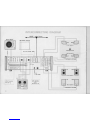
INTERCONNECTING DIAGRAM 4
CONNECTING YOUR KR-6340 5
CONTROLS AND THEIR FUNCTIONS 8
OPERATING INSTRUCTIONS 10
RM/SQ/CD-4 INTRODUCTION 12
MAINTENANCE 13
TROUBLE SHOOTING 14
KR-6340 SPECIFICATIONS 16
brought to you by www.stephsrecordsale.com

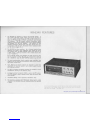
KR.6340 FEATURES
1. The KR-6340 can function as a two or four channel receiver. It
has a built-in RM type (regular matrix),and SQ type decoders so
that it is capable of reproducing both RM and SQ encoded discs,
tapes and FM broadcasts in brilliant quadraphonic sound through
four speakers. The RM decoder enhances conventional stereo
programs by decoding the ambience found in most stereo programs
and applying it to the rearspeakers. This receivercan also
reproduce discrete 4-channel tapes,and CD-4 discrete discs too,
in conjunction with the CD-4 demodulator KCD-2 (optional) which
can be simply plugged into it.
2. The KR-6340 has four amplifiers. As a 4-channel receiverthese
amplifiers are made to work separately,each drivingone of the
four speakerswhen the AMP CONTROL switch (rear panel) is set
to 4CH position. Powerper channel is then 15 watts into 8 ohms
at 20 - 20,000 Hz.
As a 2-channel receiver, the amplifiersare made to work in pairs
and are capableof driving 40 watts per channel into 8ohms at
20- 20,000 Hz, when the AMP CONTROL switch is set to 2CH.
3. The semi·complementary directly coupled power amplifiers have
widebandand low distortion characteristics which ensure smooth,
high fidelity amplification.
4.Tone,Balanceand Volume controls are designed to permit fine
adjustments of 4-channel sound to suit various programsources
and listening conditions.
5.Two pairsofspeakers connectingterminals are availabletopermit
simultaneous listening at two different places.
6.A DoubleSwitchingDemodulator (DSD) is usedin the MPX section.
This DSD method is used to prevent carrierleaks and ensure best
sound quality.
8. This receiver is equipped with FM Detector Output jack to enable
reception of FM discrete 4-channel broadcasts when this becomes
areality.
Do not connect the power cord to the AC outlet, before ascertaining that
the position of AC Voltage Selector Switch on the rear panel corresponds
with your line voltage. (see page 13.)
brought to you by www.stephsrecordsale.com


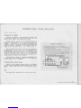
CONNECTING YOUR KR·6340
Connecting The "A" Speakers
Place the four speakersin yourlistening room as shown in the
interconnectingdiagram.Your listeningposition shouldbe atthe
center of thefour speakers,and facing the front speakers.
Speaker connections are made to the "A"SPEAKERS terminals as
follows. Theleft-front speaker's (-) side should be connected to the
L-FRONT (-) amp terminal.Its
(+)
side should be connected tothe
L-FRONT
(+)
terminal. Theright-front,left-rear and right-rear speakers
should be connected, respectively, to the R-FRONT, L-REAR and
R-REAR terminals in the same manner,
(+)
to
(+)
and (-) to (-).
Any two-conductor wiresuchas an AC cord can be usedas a
speaker cord, but a "zip-cord"which is colorcoded ismost convenient
for makingproper
(+)
to
(+)
and(-)to (-) connections. Itis
recommendedthatspade lugs aresoldered to the tipsof the speaker
cord leads. Whenspade lugsarenot used,be sureto twist together the
strandsof each individual lead to eliminate any possibility ofshort-
circuits formingin thespeaker connecting network.
Speaker phasing canbe determinedin the followingmanner:
1.Set the SELECTOR switch to FMand presstheA SPEAKERS button.
2.Setthe MODE switchto MONO.
3.Tunein thedesiredstation withtheTUN ING knob and adjust the
VOLUME control tothedesiredlistening level.
4.If the sound is comingdirectly from thefront,thespeakers arein
phase. If the soundcomes from bothsides and thereisanoticeable
loss in lowfrequencies,the speakersareout of phase. Inthis case
reverse theleads on onespeaker.
If
you intend to use only the "A"speakers for conventional2-chan-
nel stereo,theyshould bepositioned at the front. Be sure make proper
(+)
to
(+)
and (-) to(-) connections.
Connecting Additional Speaker Systems
When you connect additional speakersystems to theKR-6340,
connections to the "B"SPEAKERS terminals should be made as describ-
ed above.Observe polarity at all times when makingspeaker connec-
tions.
Reverseconnections of either
theLEFT or RIGHT speaker.
brought to you by www.stephsrecordsale.com

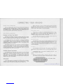
CONNECTING YOUR KR·6340
Since FM broadcast signals travel along a straight,direct-line path,
they 'becomerather weak behind hills and buildings even in the vicinity
of a broadcasting station.FM signals also become weak in areas distant
from a station even though there may not be any obstruction to the direct
stalledin the most effective manner for best possible FM reception.
In areas nearthe FM station,where signals are strong, stretch the
T·typeindoor antenna that is supplied, to its maximum, and connect it
to theFM 300 nANTENNA terminals. This antenna should be carefully
hung in thedirection that provides best reception and clarity.
Inareas subjectto FM multipath interference such as locations be·
hind hillsorin the shadow of buildings,an outdoor FM antenna should
be used.An outdoor FM antenna is also recommended for the reception
of weak anddistant FM stations.Connections should be made as
/
~Locate the mostsensitiveposi-
tion withinthese points.
follows:300 ohm twin leads should beconnected to the FM 300 n
terminals,and 75 ohm coaxial cable to the FM 75 nterminals.
Connecting The AMAntenna
The AM ferrite loopstick antenna built into your KR-6340 assures
satisfactory reception of all local AM stations.Since the ferrite loopstick
antenna has directional properties,you should adjust the antenna to the
position which brings in the strongest signal.
In fringe areas or in locations surrounded by steel frame buildings
where satisfactory reception cannot be obtained with the ferrite loopstick
antenna,an AM outdoor antenna should be connected to the AM terminal.
AC cords,speaker leads, etc. which run adjacent to antenna may
interfere with reception. Keep them away as far as possible from the
AM ferriteloopstick antenna.
brought to you by www.stephsrecordsale.com

CONNECTING YOUR KR·6340
The two shieldedaudio cables from your stereo record player are
normally terminated with phono plugs. Connect the left channel of the
record player to the "L" PHONO input jack, and the right channel to the
"R" PHONO input jack. If the record player has a groundingwire,con-
nect it to this receiver's GND terminal to avoid hum.
Connecting Four-Channel Tape Recorder
Recordingand playback of discrete 4-channel tapes can be made
with this receiver by connectingshielded audio cables with phono plugs
from a four·channel tape deck to the TAPE jacks of this receiver.
A 4-channel deck can be connected as followsfor recording;
front-left channel input of the deck connects to the FRONT-L REC jack
of the KR-6340. Similarly,make the front-right,rear-left and rear-right
connections between the correspondinginputs of the deck to the
respective REC jack of thereceiver.
A 4-channel taperecorder can be connected as follows for playback;
front-left channel output of thetape recorder connects fo the FRONT-L
PLAY jack of the KR-6340.Similarly, make the front·right,rear-left and
rear-right connections between the corresponding outputs of thedeck
to the respectivePLAY jacks of the receiver.
If conventional 2-channel stereo tape recorders are used for both
recording and playback, connections should be made to the TAPE
FRONT jacks. The recording inputs of the tape recorder connect to the
FRONT REC jacks of the KR-6340. Use shielded audio cables with
phono plugs. The playback outputs of the tape recorder connect to the
FRONT PLAY jacks of the KR-6340.
If your tape recorder is equipped with a DIN type 5-pin connector.
connect it to the DIN connector with a DIN connecting cord.A DIN
connector enables recording and playback with this single cord.
When aDIN cord isused toconnect the tape recorder,the PLAY
and REC jacks should not be used.Forhighest fidelity recording and
playback it is recommended that thetaperecorder be connected to the
PLAY and REC jacks instead of the DIN connector.
These inputs aresuitable for connectinghighlevel discrete 4-chan-
nel sources such as another 4-channel tape recorder,or a CD-4
demodulatorotherthan theplug-in type CD-4 demodulator that is
availableas optional equipment withthe KR-6340.
Use the FRONT AUXjackswhen connecting 2-channel high level
sources such as a tuner or anothertaperecorder.
The FM detector circuit output ismade availablehere so that this
receiverwill be ready for 4-channel broadcasting developments in the
future.When FM discrete4-channel broadcastingbecomes areality,
asimple demodulator connectedhere will enableyouto fully enjoy this
comingdevelopment.
TheAC outlet onthe rear panelof the receiver may be used to
supply power to other components suchas a record player,tape recorder,
etc.
UNSWITCHED outlet - Thisoutlet is available at alltimes.(The
maximum capacity is 200 watts.)
NOTE:
When AC convenienceoutlet is covered on your set as shownin
this diagram, consultyour dealer orserviceman when itisneeded.
brought to you by www.stephsrecordsale.com

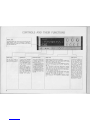
CONTROLS AND THEIR FUNCTIONS
Themeter indicatesthe intensityof theincoming FM or AM
signal. Pinpoint tuning for any broadcastis indicated by
maximum deflection.Siml'lly tunefor highest meterreading
withthe TUNING knob.
PushthePOWER switchto
turnthereceiver on.Pushit
againto turn the receiver off.
2-Channelstereo: Plug stereo
headphones into the FRONT
jackfor privatelistening and
turn off the speakersby leav-
ing theSPEAKERS buttons
Aand B in the extended
"out"positions.
4-Channel Stereo: Insert 4-
channelstereo headphone
plugs into theFRONT jack
forfrontside and REAR jack
for rearsidereproductions.
TheAand B SPEAKERS
buttons shou Id be setto
extended"out" positions.
Pressing these buttonsturns
the speakers on. Whenthey
are pushed again, all the
speakerswill turn off.
A:Pressing this button turns
onthe speakers connected to
theA SPEAKERS terminals.
Releasing thisbutton (press-
ingit again) turnsthem off.
B: Pressing thisbutton turns
onthe speakers connected to
theB SPEAKERS terminals.
Releasingthis button turns
themoff.
000
Switch positions and functions are as follows:
MONO-Sound will beheard in monophonicmode and the
signals becomemixed as one andthe same sound isheard
from all fourfront and rearspeakers.
2-CH-Conventional 2-channelstereo reproduction isobtain-
ed from thefront speakers only.The "2CH"indicator will
lightup.
RM-Thisposition isused to play"regular matrix" encoded
sources through theregular matrix decoder in 4-channel
sound.Also, itcan beused to enhance conventional 2-
channelsources by applying ambience to therearspeakers.
The"RM" indicator will lightup.
SO-This position is used toplay SO encoded records. tapes
or FM broadcaststhrough the SOdecoder in 4-channel
sound.The"SO"indicator will light up.
DISCRETE -This position isused fordiscrete 4-channel
stereo reproduction.The "DISCRETE"indicator will light
up.
The BASS and TREBLE con-
trols are foradjusting the
bass and trebletone.These
aredualconcentric friction
type controls. Theouter
knob controlsfront sideand
theknobadjacent to the
panelcontrols the rear side.
By holding one knob firmly,
the other may berotated
separately, thus providing in-
dependent tonelevel adjust-
mentof the front or rear
sides.Each knob controls
both left and right channels
equally.Turning the knobs
clockwise inreases bassor
treble tone and counterclock-
wise decreases them.Toneis
flat at center "0" position.
brought to you by www.stephsrecordsale.com

CONTROLS AND THEIR FUNCTIONS
AMPLI FI ER MODE
indica-
tor lamp
Either the4CH or 2CH lamp
lights up to indicate the set-
ting of the
AMP
CONTROL
switch on the rear panel
which determines the mode
of the amplifiers. The switch
is preset at the factory for 4-
channel amp operation so
the 4CH pilot lamp should
light up unless the switch has
been reset for 2-chan nel amp
operation.
This switch silences interesta-
tion noise on the
FM
band,
but it may also eliminate the
signal of a weak and distant
station along with the inter-
station noise. Therefore, set
this switch to off(by press-
ing button release) when re-
ceiving a weak or distant
station.
The LOU DN ESS control
boosts bass and treble tones
at low listening levels. Our
ears haveless sensitivity to
low and high frequencies at
low Iis.tening l-evels, and the
LOUDNESS control com-
pensates for this deficiency.
This control should be
switched off when listening
at normal and high levels.
The TAPE MON(lTOR)
switch is used when operat-
ing a tape recorder for moni-
toring a recording or fo'r tape
reproduction.With the but-
ton pushed in, sound re-
corded on the tape is heard.
When the button is released,
the source signal is heard.
The tape monitor switch
should be kept switched off
(by button release) unless
monitoring or tapeplayback
isperformed.
The TUNING knob selects
the desired
AM or FM
station
signal. Adjust it for maxi-
mum deflection of the SI G-
NAL meter as you listen to
the sound output from the
speakers.
VOLUME control
This is a dual concentric friction type knob which permits
all four channel levels (front left and right, rear left and
right) to be adjusted simultaneously. However, by holding
one knob firmly, the other may be rotated separately. The
large outer knob adjusts the volume levels of both rear-left
and rear-right speakers simultaneously. The smaller center
knob adjusts the levels of both front-left and front-right
speakers simultaneously. Volume is minimum at full counter-
clockwise position. Rotation clockwise increases volume
level.
Switch positions and func-
tions are as follows:
AM -
For AM reception.
FM -
For FM monaural and
stereo reception.Automatic
switching is performed for
FM monaural and stereo
sources. When an FM stereo
broadcast is tuned in, the
"FM STER EO" indicator
lights up.
PHONO - In this position
the record p'layer is available
if one is connected to the
PHONO input jacks on the
rear panel.
CD-4 -Use this position for
reproducing CD-4 discrete
disc records, in conjunction
with a CD-4 demodulator
"KCD-2" (optional equip-
ment - see under "Operating
Instructions"). The "CD-4"
indicator will light up.
"RADAR" lights up to
indicate actual CD-4 discrete
disc reproduction in progress.
AUX - Selects source con-
nected to the AUX input
jacks.
This is adual concentric
friction type control. By
holding one knob firmly, the
other may be rotated sepa-
rately,thus providing in-
dependent balance level ad-
justment of the front or rear
sides.
When BALANCE is set at
"0" position, both left and
right speakers operate at the
same power. When it is turn-
ed to the left, the left chan-
nel is accentuated.When
turned to the right, the right
channel is accentuated.
brought to you by www.stephsrecordsale.com

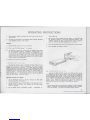
OPERATING INSTRUCTIONS
The KR-6340 is equipped with an AMP CONTROL switch located on
its rear panel to control the operation of its four independent amplifiers.
This switch is preset at the factory to the 4CH position for four channel
operation with all four amplifiers operating independently to feed the
front left, front right, rear left and rear right speakers. This is indicated
by the illumination of the "4CH" lamp on the front panel when the
receiver is turned on.
The followinginstructions indicated by asterisks
(*)
refer to
operation when the Amp Control Switch is set to 4CH position.
*
FM RECEPTION
2. Push the SPEAKERS buttons in accordance with system arrange-
ment.
3. Set the MODE switch to 2CH (12CH"indicator lights up) and the
TAPE MON switch to off (by button release).Use Mutingswitch
only when it is necessary or desired to suppress interstation noise.
In such a case, push it in. This Muting switch,however,should
be left off in ex~ended position if the incoming signal is weak.
4. Tune in the desired station with the TUNING knob.Tunefor
maximum deflection of the SIGNAL meter. This indicates proper
tuning.
5.The "FM STEREO" lamp lights up automatically when an FM stereo
station is tuned in.Set the MODE switch to MONO if the received
FM stereo signal is weak in relation to noise level.
7.Set the MODE switch to RM for regular matrix encoded incoming
FM broadcasts ("RM" indicator lights up), and to SQ for SQ
encoded FM broadcasts. ("SQ" indicator lights up).
1.
Set the SELECTOR switchto AM.
2. t th MOD witchto 2CH("2CH"indicator lights up) and the
3. Tune in the desired station withtheTUNING knob. Finetune for
maximum deflection of the SIGNAL meter.
4. Adjust the VOLUME control as desired.
5. Adjust the BASS,TREBLE andBALANCE controls as desired.
2.Set the TAPE MON switch to off (by buttonrelease). If you wishto
use a conventional stereophonic disc, set the MODE switchto 2CH
("2CH" indicator lights up).You canget quadraphonic sound from
a conventional stereo disc throughtheregularmatrix circuit, by
setting the MODE switch to RM. Set theMODE switch to SQ for
reproduction of SQ discs and to RM forplayback of regular matrix
encoded discs.
3. Adjust the VOLUME,BASS,TREBLE,LOUDNESS and BALANCE
controls as desired.
If you wish to use the KR-6340 with 3-head type tape recorders,
you can check the sound quality of the recording that is being made by
momentarily comparing the original sound with recorded signals as
follows.
Push in the TAPE MaN switch ("in"position) to monitor the
recorded signal. Release the TAPE MON switch ("out"position) to
reproduce the source signal before it is recorded.
2. Commence recording.To monitor the recording,push in the TAPE
MON switch ("in"position).
brought to you by www.stephsrecordsale.com

OPERATING INSTRUCTIONS
3. Recording level should be adjusted with the volume control of your
tape recorder.
4. Recording is not affected by the VOLUME, BASS, TREBLE, BALANCE
and LOUDNESS controls of the receiver.
2. Push in the TAPE MON button ("in" position).
3. For playback of discrete 4 channel tapes, the MODE switch should
be set to DISCRETE position ("DISCRETE" indicator lights up).
For conventional 2 channel tape playback, set the MODE to 2 CH.
If you wish to get 4 channel sound from conventional 2 channel
stereo sources,set the MODE switch to RM position. Set the MODE
switch to SQ for SQ encoded tape playbacks and to RM for regular
matrix encoded tape reproductions.
Reproduction of CD-4 discs is possible with this receiver in con·
junction with the KCD-2 (optional equipment) which can be easily
plugged into the receiver's rear panel. The plug-in connector is located
under a covering lid at the lower left corner of the receiver's rear which
can be taken off by removing two screws. Position the KCD-2 with the
arrowhead mark on the front panel pointing up when making the
plug·in connection.Remember that the player must have a suitable
CD-4 cartridge, and it is recommended that low capacity connecting
cables be used between it and the receiver.
1. Set the SPEAKERS buttons as desired. Release the TAPE MON
switch to extended "out" position.
2. Set the SELECTOR switch of the KR-6340 to CD-4 position ("CD-4"
indicator lights up however,this indicator will not light unless
KCD-2 is inserted).
3. Set the MODE switch to DISCRETE position. ("DISCRETE" in·
dicator lights up).
4. Play the test record supplied with the KCD-2 in accordance with
the directions outlined in the KCD-2 Operating Manual. The
"RADAR" indicator will light up when the test record is played to
show that CD-4 discrete disc reproduction is in progress.
AMP CONTROL SWITCH SET TO 2CH
Switching the AMP CONTROL switch to the 2CH side lines up the
two amplifiers on the left side to work as one,and the two amplifiers
on the right side also to work as one. This more than doubles the
stereo two-channel power output. (15 watts per channel into 8 ohms at
20 - 20,000 Hz in 4-channel mode;40 watts per channel in 2-channel
mode). This is indicated by the illumination of the 2CH indicator on
the front panel. When the amplifiers are worked in this manner, the
MODE switch should.be set to either 2CH or MONO as desired.
NOTE:
Always leave the power switch off when resetting the AMP CONTROL
switch. Otherwise it will activate the protection circuit to momen·
tarily cut off sound.This does not indicate damage, however.
brought to you by www.stephsrecordsale.com

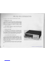
RM/SQ/CD-4 INTRODUCTION
TheRM regular matrix system produces four-channel sound in
twoways;ie, from conventional 2-channel sources through a synthesizing
actionasin the so-called 2-2-4 system, and from 2-channel material
(originally encoded from 4 channel discrete sources) through a decoding
action back to 4-channels as in a so-called 4-2-4 system. In both,
4-channel sound is produced from 2-channel Land R signals by adding
to,orsubtracting from them.
Sansui, Scheiber, E-V, Dynaco,etc. utilize the RM system. They
have some respective differences, but they can all be reproduced
practically in the same manner.
In principle this is a4-2-4 system which is a fundamental improve-
ment over the RM system with better Front-Rear and Left Right separa-
tion. Also there is none of the unnaturalness sometimes encountered
with conventional RM methods when reproduction is made in stereo or
monaural modes.This is a superior method also for reproducing 4CH
discs when only ordinary, conventional stereo cartridges are used.
CD-4 discs contain the main stereo signals includingthe Land R
channels to which are added the Front-Rear characteristics. This is
mixed with a difference signal that is FM modulated on a 30 kHz carrier
when the stereo record is cut. Therefore, a special CD-4 cartridge
capable of reproducinghigh frequencv ranges up to 45 kHzbecomes
necessary for CD-4 reproduction of CD-4 discs. Moreover, a special
CD-4 low capacity cable is necessary for connection between the
cartridge and the demodulator.
Thus, special attention must be given to the use of a CD-4 cartridge
and cable,but this will enable a perfect, discrete 4-channel reproduc-
tion.
brought to you by www.stephsrecordsale.com

MAINTENANCE
Transistorsdiffer fundamentally from radiovacuum tubes and
require special attention to ensure their full performance capabilities.
Given proper care,transistors will provide years of practically trouble-
free performance.
(a) Avoid locations subject to direct sunlight.
(b) Avoid high or low temperature extremes.
(c)Keep the receiveraway from heatradiating sources.
The newly developed protection circuit is completely effective and
prevents damage which may be caused by short-circuiting at the speaker
outputs or the electrical overloading point.When ashort-circuit occurs,
this protection circuit will function automatically to protect the power
output transistors.Theprogram sound will be heard off andoninter-
mittently about every fourseconds.If this occurs,there isnofear of
damage to the power output transistors.Just switch off the supply
line and check the speakerconnections.
ACOUSTIC FEEDBACK
Occasionally adisturbing howling sound caused by acoustic feed-
back,may be heard. This isgenerally caused by the relativepositions
of the turntable and speaker enclosures. The sound pressure radiated
from·the speaker box surrounds and vibrates the turntable. This
vibration is picked up by the cartridge,sent to the amplifier asan
electrical signal,and returned to the speaker.This again causesthe
speakers to radiate vibration which induces sympathetic vibrationsin
the turntable and cartridge.Sympathetic vibrations are reinforced with
each repeatingcycleand result in an undesirable sound called oscil-·
lation or "howling". To prevent it,keep your turntable away from
your speakers. Also mounting your turntable on shock-absorbing pads
may help.
Do notusealcohol,thinner or gasoline whencleaningthereceiver
surface. Useasilicon cloth or a soft dry cloth.
The KR-6340 operates on 110-120 volt AC or 220- 240 volt AC.
The AC Voltage SelectorSwitch on the rear panel is set to the voltage
that prevails in the area to which thereceivers are shipped.Before
operating this receiver, makesure that theposition of the AC Voltage
Selector Switch matchesyour linevoltage.If not,it must be changed
to the proper setti ng.
To change,first turnthe receiver off,then removethestopper·
plate and slide the AC Voltage Switch to theopposite side. Thenre-
attach the stopper plate tothe other side.
When theposition of theACVoltage Selector Switch is changed,
it isalso necessary to change thepower fuse.For 110 -120 volt opera-
tion a4 ampere fuse should be used. For 220- 240 volt operation a 2
ampere fuse should be used.
If the power fusefails,removeblown fuse and replace with the
same type fuse of the same capacity. Any troublein the powersupply
circuit will cause the fuseto blowagain.In such acase, consulta
quaIifi ed serviceman.
When you replace the fuse,turn the fuse holder in the direction
of the arrow usinga Phillips screw driver. In some districts,the set
will be provided with another type offuse holder,which allows easy
replacement of thefuse without usingthePhillips screw driver.
1. Always disconnect powersupply before replacing a fuse.
2. Ourwarranty doesnotcover damage caused by excessive line
voltage due to improper settingof theAC Voltage SelectorSwitch.
II 0-120V" ~!220 -240V II 0-120V" ~ 220-240V
(ACI20V"~ AC220V)(AC120V •• ~ AC220V)
@~@
Stopper plate
I.Removescrew andstopper plate.
2.Switch leverto opposite side.
3.Locklever
by
attaching stopper
plate to opposite side screw.
brought to you by www.stephsrecordsale.com

Continuouslow frequency buzz.Most notice-
able at night on weak signal stations.
Continuous highfrequency whine which in-
creases at night.
Continuoushiss or buzzing interference with
broadcast. Becomes louderduringstereo.
Weak right channel responsewhen listening
to LEFT only test FM Stereo broadcast.
FM Automatic Circuit fails to respond to stereo
broadcast.
TROUBLE SHOOTING
In initially installingthis receiver, improperconnections may resultin one of
the following indicationsof trouble.Theirpossible causes and correctivemeasures
are listed below to facilitate installation.
Interference from electrical appliances or at·
mospherics.
TV interference.
10 kHz beat interference from adjacent AM
station.
Lightninginterference.
Interferencefrom fluorescent lamps.
AC PlugConnection.
CalledBCI,this interference results from
neighboring amateur stations.
(Also occurs on FM)
Automobile ignition noise.More noticeable on
weak signals.
Called crosstalk, avery slight response is
normal.
Erecting a 10meter outdoor antenna andsecuring
good ground conditions should reduce interference
considerably.Complete elimination is difficult.
Turn TV off. (Neighboring TV set mayalso be cause.)
Impossible toeliminate from receiver side.This is
one disadvantage of the AM broadcast system. Use
High Filter to cut off high frequency interference.
Occurswhen lamps are onand cannot be helped.
TryreversingAC plug connections.
Occurs only oncertain stations dueto high voltage
powerline and cannot be helped in many areas.
Consult interferingstationoperator or authorities
concerned.
Erectoutdoor FM antenna if only indoor T-type is
used.A 5 or 7 element antennais necessaryif you
are located ata considerable distancefrom the
broadcastingstation.
Erect outdoor FM antenna as far away from roads as
practicable.
If leakage is less than one tenth,it is notasignof
trouble.
It cannot be reducedto zero.
brought to you by www.stephsrecordsale.com

TROUBLE SHOOTING
Nopilot lamp Incllcation,no sound although AC
is switchclN.Poor AC plug connection.
Blown fuse.Check plug contact.
Replace fuse.If it blows again, trouble must be
corrected.
No sound can beheard from the FRONT side
lor 4-channel reproduction.
The rear sound level is loweredwhen the MODE
witch isset to RM.
Noise when AC is switched ON orwhen volume
is adjusted immediately after.
Unbalance resultswhen volume is lowered.
Intermittentspeaker response at4seconds
intervals.
Difference in volume level of radio and phono.
Check connections from amp. output to speakers.
Push IN the speaker button whichactivates the
speaker systems desired.
Set to appropriate volumelevel.
Always set to OFF exceptwhen using tape recorder.
Checkamp.output and speaker connections.
Adjust BALANCE control.
Change the connection to the FRONT terminals of
the AUX or TAPE.
For 4-channel stereo reproduction through the regular
matrix circuit,use the 2-channel program source.
Allow 5 -6 seconds interval after switchingAC ON,
before manipulating volume control.
Adjust BALANCE control.
Check speaker cord connections.
Nunci from LEFT and RIGHT, FRONT and
Hll\lt
Speaker cords disconnected.
SPEAKERS buttonsOFF (button release).
VOLUME Control at 0 (extremeleft).
TAPE MON switch at ON position (button push).
Poor speakercord connections.
BALANCE control set to oneextreme or other.
The 2CH source is connected to the REAR
terminals of theAUX or TAPE.
The program source is monaural.
LEFTRIGHT resistorvalues unbalanced.
Protection Circuitindication of short circuit in
theoutput.
Difference in received signal and phono output
levels.
See thatplayer output cord is firmly plugged into
Amp. input.
See that player output cord is firmly plugged into
Amp.input.
-----------------------------------------------------------------
Keep player output cordaway from AC cords.
Choose cordpaths whichkeep hum ataminimum.
Twist LEFT RIGHT player outputcords together.
Reverse player AC plug connections.
Connect playerground wire to GND terminal.
Route player cord so that buzz isminimized.
No sound from LEFT andRIGHT,or sound only
from one side.
Loud hum drowns out sound.
Player output cord picking up hum from AC
cord.
Howling noiseoccurs when volume is raised or
bass response is increased.
Player not grounded.
TV signal picked up by Player output cord.
Frequently occurs near TV transmitting antenna.
Speaker vibration induce feedback in pickup.Increase distance between player and speakers.
Choose speakerlocations carefully.Remember, loose
flooring induceshowling.
Soundaudible butcontinuous background buzz
interferes.
brought to you by www.stephsrecordsale.com

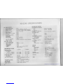
FMTUNER SECTION
UsableSenItlvlty (IHF)
Frequency Response
HarmonicDistortion
SI nalto Noise Ratio
ImageRejection
Selectivity (IHFALT. channel)
IF Rejection
Spurious Signal Rejection
AM Suppression
capture Ratio
Stereo Separation
Sub Carrier Suppression
Antenna Impedance
Usable Sensitivity (IHF)
Signal To Noise Ratio
Image Rejection
Selectivity (IHF)
IF Rejection
Antenna
RMS Power Output
Full channel driven
into 8 ohms
at 20 Hz -20,000 Hz
into 8 ohms at 1,000 Hz
into 4ohms at 1,000 Hz
Dynamic Power Output
into 8 ohms
into 4 ohms
Total Harmonic Distortion
Intermodulation Distortion
(60 Hz:7kHz
=
4: 1)
Power Bandwidth
Damping Factor
Speaker Impedance
KR.6340 SPECIFICATIONS
2.0
J.'
V.
20 Hz - 15,000 Hz
±
1.2 dB.
0.5% Mono (at 400 Hz 100%modulation).
0.8% Stereo (at 400 Hz 100%modulation).
63 dB at 1 mV input.
60 dB.
50 dB.
90 dB.
90 dB.
60 dB.
3.0 dB.
40 dB at 1,000 Hz.
20 dB at 10,000 Hz.
45 dB.
300 ohms Balanced &75 ohmsUnbalanced.
25
J.'
V.
45 dB at 1 mV input.
45 dB.
30 dB.
35 dB.
Built-in ferrite bar antenna, External
antenna terminals.
15 x 4 watts
20 x 4 watts
23 x 4 watts
40 x 2 watts
50 x 2 watts
47 x 2watts
120 watts 170 watts
152 watts
0.8% at rated powerinto 8 ohms.
0.3%at
1Iz
rated power into 8 ohms
at 1,000 Hz.
0.8%at ratedpower into 8 ohms.
0.3% at
1/2
rated power into 8 ohms.
20 Hz - 40,000 Hz.
20 at 8 ohms (4 channel operation).
Accept 4ohmsto 16 ohms.
InputSensitivity and Impedance
Phono
AUX
Tape Play
Maximum Input Voltage (rms)
Phono
Signalto Noise Ratio
Phono
AUX
Tape Play
Output Voltage and Impedance
Tape Rec. (Pin)
(Din connector)
Frequency Response
Phono
Tuner,AUX, Tape Play
Tone Controls
Bass
Treble
Loudness Control ( - 30 dB)
Switches
Speaker Selector
Input Selector
Mode
Tape Monitor
Others
AC Outlet
Power Consumption
1.5 mV,
150 mV,
150 mV,
100 k ohms.
50 K ohms.
50 K ohms.
60 dB.
75 dB.
75 dB.
150mV,100 ohms.
40 mV.
RIAA Standard curve
±
1 dB.
20 Hz- 20,000 Hz
±
1 dB.
±
10 dB at 100 Hz.
±
10 dB at 10,000 Hz.
+
10dBat100 Hz.
+
5 dB at 10,000 Hz.
A,BPush Switch.
AM, FM, PHONO, CD·4, AUX.
MONO, 2ch,RM, SQ, Discrete.
Push Switch.
Loudness,AMP Control,FM Muting,
Power.
Unswitched 1.
320 watts at full power.
35 watts at no signal.
W21·27/32"(555mm),
H 6·5/16"(160mm),
o
14·3/16"(360mm).
33 Ibs.(15 kg).
brought to you by www.stephsrecordsale.com


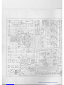
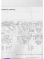
I'~
==7'.
S3~
1::-
53-If
,~
53-21
jjp.
-Q)
;)f,:2SC',345 D
;f2-5:2SA62OWL5·
:l:6,7:2SCI213A8orC
Jf8,9:2SCI212A B
or
C
~.1l:2SA
743A 8
or
C
~r2-r5:2SCI444
)f1,2
:STV-3-H
Jl3,<:IS2076
:lI,
:Wl081
4o..A II
~03
)3K
'-';;l
I
I
I
I
I
I
II
L
~---J
SPEAKERS SEL
,,~..!.4~..!.0_,
I
~'IIl'K
51
"
,
,
G
e
IIlNI IK
fr'
"
,
II~~
Oel:2SC1345 D
Oe2-5:2SA620WL5
Qes,7:2SC1213ABor C
Qes,9:
2SCI212A B
or
C
OeloJI:2SA743A8 orC
Qel2-ls
:25C144 4
Del,2:STV-3- H
De3,4: 152076
De' :Wl-081
~
PHONES
TUNER IX05-1080-14)
r---------N-------
I
q
c"!"
I
00'
ANT~lT\~~,'
I°1-'I
i ~
i
I..
UO. •.
,-~
"REAR
PHONES
Qpf,2
:25C14J6
QP3,6:2SA733
Op4,5:2SC828A
Dpl-.:IS2076
DP7,8:W06B
-;;;-+
:;:FL
~
~tR
~-
~+
~RL
~
,---(§)+
~-(§):'"
-
-
[::~
===
~-(§)+
~"
~-
~;
~+
::;:::~
~
BARih
ANT
I
W,
I..81
L·_.__._
00'
3SK30BLACK ®.©
0913
2SCI2J3~::
092~4
25C381
®
leg,
pPC555t.
09:5,6
2SC53S®
091,:5-12
OOT
2SC94S®
0914-18,20-27
IN60
OOB
2SC785@,@
093,4,13,19
IS 1555
00'
25C941
0929,30
MV-13
0010
2SA733@,@
lOI
OZ-140
09
11•12
2SC458®
brought to you by www.stephsrecordsale.com
Page is loading ...
Page is loading ...
Page is loading ...
-
 1
1
-
 2
2
-
 3
3
-
 4
4
-
 5
5
-
 6
6
-
 7
7
-
 8
8
-
 9
9
-
 10
10
-
 11
11
-
 12
12
-
 13
13
-
 14
14
-
 15
15
-
 16
16
-
 17
17
-
 18
18
-
 19
19
-
 20
20
-
 21
21
-
 22
22
-
 23
23


