Page is loading ...

77-1889-R16 (5/2021) 1 / 4 www.carlisleft.com
ITEM PART
NO. NO. DESCRIPTION
QTY.
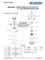
1 20-262 NUT,
1/2-13 .................................. 1
2 20-783 SCREW,
1/4-20 .............................. 6
3 20-4401 PLUG,
1/4 NPT .............................. 1
4 20-2848 ELBOW,
1/4 NPT ............................ 1
5 20-5632 NIPPLE,
1/4 NPT ........................... 1
6 83-2744* GAUGE,
200 PSI ............................ 1
7 84-328 DISC ......................................... 2
8 84-330▲ DIAPHRAGM,
NYLON ..................... 2
9 84-348* CONNECTOR ............................... 1
10 84-351 HANDLE ..................................... 1
11 84-359 BONNET ..................................... 1
12 84-362 RETAINER .................................. 1
13 84-363 ■ VALVE
(84-404, 84-504) .................... 1
14 84-365 SPRING ..................................... 1
15 84-388▲ GASKET,
VELLUMOID ...................... 1
16 84-399▲ DIAPHRAGM,
PTFE ....................... 2
17 84-454 ■ SEAT
(84-404, 84-504) ..................... 1
18 84-455 BODY,
3/4 NPT(f) (84-404) ................ 1
19 84-463▲ GASKET,
VELLUMOID ...................... 1
20 — BODY, 1-1/4 NPT(f) (84-504) .............. 1
21 85-10 BUTTON ..................................... 1
PARTS LIST
When ordering, please specify Part No.
NOTE: The following items are obsolete
(refer to Part Sheet 1889R-7):
84-530 BACK PRESSURE VALVE
84-544 BACK PRESSURE VALVE
SEE PAGE 3 FOR INSTRUCTIONS.
* Optional, not furnished. Please order separately.
▲ Also available in Soft Seal Repair Kit 6-1310.
Kit not included, please order separately.
■ Also available in Valve Repair Kit 6-1312.
Kit not included, please order separately.
MODEL INLET & OUTLET FLOW COEFFICIENT
84-404 3/4 NPT(f) CV = 2.0 MAX.
84-504 11
⁄
4 NPT(f) CV = 2.0 MAX.
6
9
4 5 18 20
17 13 7
3
15
16
8
19
2
12
14
21
11
1
10
15
8
16
8
16
19
See insets
at left for
detailed view.
Torque screws to
72 inch pounds.
MODELS 84-404 AND 84-504
STAINLESS STEEL BACK PRESSURE FLUID VALVES
EN
SERVICE MANUAL

EN
77-1889-R16 (5/2021)2 / 4www.carlisleft.com
LOCK OUT / TAG-OUT
Failure to de-energize, disconnect, lock out and tag-out all power
sources before performing equipment maintenance could cause
serious injury or death.
OPERATOR TRAINING
All personnel must be trained before operating finishing
equipment.
EQUIPMENT MISUSE HAZARD
Equipment misuse can cause the equipment to rupture,
malfunction, or start unexpectedly and result in serious injury.
PROJECTILE HAZARD
You may be injured by venting liquids or gases that are released
under pressure, or flying debris.
PINCH POINT HAZARD
Moving parts can crush and cut. Pinch points are basically any
areas where there are moving parts.
INSPECT THE EQUIPMENT DAILY
Inspect the equipment for worn or broken parts on a daily basis.
Do not operate the equipment if you are uncertain about its
condition.
In this part sheet, the words WARNING, CAUTION and NOTE are used to
emphasize important safety information as follows:
Hazards or unsafe practices which
could result in minor personal injury,
product or property damage.
!
CAUTION
Hazards or unsafe practices which
could result in severe personal
injury, death or substantial property
damage.
!
WARNING
Important installation, operation or
maintenance information.
NOTE
Read the following warnings before using this equipment.
READ THE MANUAL
Before operating finishing equipment, read and understand all
safety, operation and maintenance information provided in the
operation manual.
WEAR SAFETY GLASSES
Failure to wear safety glasses with side shields could result in
serious eye injury or blindness.
NEVER MODIFY THE EQUIPMENT
Do not modify the equipment unless the manufacturer provides
written approval.
IT IS THE RESPONSIBILITY OF THE EMPLOYER TO PROVIDE THIS INFORMATION TO THE OPERATOR OF THE EQUIPMENT.
FOR FURTHER SAFETY INFORMATION REGARDING THIS EQUIPMENT, SEE THE GENERAL EQUIPMENT SAFETY BOOKLET (77-5300).
KNOW WHERE AND HOW TO SHUT OFF THE EQUIPMENT
IN CASE OF AN EMERGENCY
PRESSURE RELIEF PROCEDURE
Always follow the pressure relief procedure in the equipment
instruction manual.
NOISE HAZARD
You may be injured by loud noise. Hearing protection may be
required when using this equipment.
STATIC CHARGE
Fluid may develop a static charge that must be dissipated through
proper grounding of the equipment, objects to be sprayed and all
other electrically conductive objects in the dispensing area. Improper
grounding or sparks can cause a hazardous condition and result in
fire, explosion or electric shock and other serious injury.
WEAR RESPIRATOR
Toxic fumes can cause serious injury or death if inhaled.
Wear a respirator as recommended by the fluid and solvent
manufacturer’s Material Safety Data Sheet.
TOXIC FLUID & FUMES
Hazardous fluid or toxic fumes can cause serious injury or death if
splashed in the eyes or on the skin, inhaled, injected or
swallowed. LEARN and KNOW the specific hazards or the fluids
you are using.
KEEP EQUIPMENT GUARDS IN PLACE
Do not operate the equipment if the safety devices have been
removed.
!
WARNING
AUTOMATIC EQUIPMENT
Automatic equipment may start suddenly without warning.
FIRE AND EXPLOSION HAZARD
Improper equipment grounding, poor ventilation, open flame or
sparks can cause a hazardous condition and result in fire or
explosion and serious injury.
MEDICAL ALERT
Any injury caused by high pressure liquid can be serious. If you
are injured or even suspect an injury:
• Go to an emergency room immediately.
• Tell the doctor you suspect an injection injury.
• Show the doctor this medical information or the medical alert
card provided with your airless spray equipment.
• Tell the doctor what kind of fluid you were spraying or
dispensing.
GET IMMEDIATE MEDICAL ATTENTION
To prevent contact with the fluid, please note the following:
• Never point the gun/valve at anyone or any part of the body.
• Never put hand or fingers over the spray tip.
• Never attempt to stop or deflect fluid leaks with your hand,
body, glove or rag.
• Always have the tip guard on the spray gun before spraying.
• Always ensure that the gun trigger safety operates before
spraying.

EN
77-1889-R16 (5/2021) 3 / 4 www.carlisleft.com
BINKS STAINLESS STEEL BACK PRESSURE FLUID VALVES, MODELS 84-404 & 84-504
INSTRUCTIONS
INSTALLATION:
1. When installing back pressure valve assembly,
make certain that ARROW underneath valve
body points toward DOWNSTREAM side of
system.
2. Make certain that inlet and outlet connections are
tight.
3. If valve is installed in other than the upright
(vertical) position, make certain that the gauge
assembly (6) is in the upright position in all
cases. The gauge assembly may be installed in
either of the 1/4 NPT outlets.
OPERATION:
1. With system in operation, turn handle (10) in a
clockwise direction until desired back pressure or
flow rate is obtained. To reduce back pressure,
reverse procedure.
2. Tighten nut (1) to maintain desired back
pressure.
NOTE
HIGHER back pressure REDUCES flow rate.
LOWER back pressure INCREASES flow rate.
3. If back pressure valve buzzes during or after
initial startup of system, the presence of air in
the system is indicated. If buzzing continues for
any duration, reduce back pressure until buzzing
ceases. Then readjust to desired back pressure.
MAINTENANCE:
1. Back pressure valve can be serviced without
removing the valve from the line.
2. To replace diaphragms, gaskets or seats:
a. Turn handle (10) in a counter-clockwise
direction until tension from spring (14) is
relieved.
b. Remove screws (2).
c.
Remove valve (13).
3. To reassemble, reverse procedure as outlined.
When reassembling, note sequence of
diaphragms and gaskets. The gasket (15)
fits between the diaphragms (8) and (16).
The diaphragms are located below the other
gasket (19). See detailed insets on diagram on
page 1.
MODEL INLET & OUTLET FLOW COEFFICIENT
84-404 3/4 NPT(f) CV = 2.0 MAX.
84-504 11
⁄
4 NPT(f) CV = 2.0 MAX.

EN
77-1889-R16 (5/2021)4 / 4www.carlisleft.com
WARRANTY POLICY
This product is covered by Carlisle Fluid Technologies’ materials and workmanship limited warranty.
The use of any parts or accessories, from a source other than Carlisle Fluid Technologies,
will void all warranties. Failure to reasonably follow any maintenance guidance provided
may invalidate any warranty.
For specic warranty information please contact Carlisle Fluid Technologies.
Carlisle Fluid Technologies is a global leader in innovative nishing technologies.
Carlisle Fluid Technologies reserves the right to modify equipment specications without prior notice.
BGK™, Binks®, DeVilbiss®, Hosco®, MS®, and Ransburg®
are all registered trademarks of Carlisle Fluid Technologies, Inc.
©2021 Carlisle Fluid Technologies, Inc.
All rights reserved.
For technical assistance or to locate an authorized distributor,
contact one of our international sales and customer support locations.
Region Industrial/Automotive Automotive Renishing
Americas Tel: 1-800-992-4657 Tel: 1-800-445-3988
Fax: 1-888-246-5732 Fax: 1-800-445-6643
Europe, Africa,
Middle East, India
Tel: +44 (0)1202 571 111
Fax: +44 (0)1202 573 488
China Tel: +8621-3373 0108
Fax: +8621-3373 0308
Japan Tel: +81 45 785 6421
Fax: +81 45 785 6517
Australia Tel: +61 (0) 2 8525 7555
Fax: +61 (0) 2 8525 7575
For the latest information about our products, visit www.carlisleft.com
/