Oventrop 1406553 Datasheet

Type
Datasheet
Subject to changes All rights reserved EN-02101-14063-DB-V2319 1
Product Data
Multidis SF
Presettable Heating Circuit Manifold
optionally with Flow Indicat
ors
Item no. 14063 Item no. 14065
Heating circuit manifold made of stainless steel for surface
heating and cooling systems with forced circulation. For
connecting two to twelve heating circuits to the heat or
cooling generator.
The heating circuit manifold consists of a flow distributor, a
return collector, wall brackets and fixing material. The
heating circuit manifolds are completely pre-assembled
with rotatable fill and drain cocks, vent plugs and end caps.
To simplify the installation of the heating circuit pipes, the
return collector (bottom) is moved forward in the wall
bracket.
The flow distributor is equipped with integrated flow
measuring and regulating devices or with simple regulating
inserts. The return collector is equipped with valve inserts
with M 30 x 1.5 connection thread to connect optional
actuators. These are factory-fitted with a protection cap,
which can also be used to temporarily shut off the heating
circuit.
The heating circuit connections with G ¾ external thread
are suitable for Oventrop compression fittings. Sound
insulation according to DIN 4109.
Functions
Regulation of the heating circuit flow rate
Flow rate check per heating circuit (item no. 14063)
Heating circuit shutoff
Filling, venting, draining
M 30 x 1.5 connection thread for actuators
Features
+Static setting of the flow rate, optionally with flow
indicators
+High-quality stainless steel version
+Complete with wall brackets for installation in a
surface-mounted or a flush-mounted cabinet or in a
niche
Product Data Multidis SF
Subject to changes All rights reserved EN-02101-14063-DB-V2319 2
Product Details
Technical Data
Item no. 14063
with flow measuring and regulating devices Item no. 14065
with regulating inserts
Heating circuits 212 212
Variant Flow distributor: flow measuring and regulating devices
Return collector: valve inserts with connection thread
M 30 x 1.5
Flow distributor: regulating inserts
Return collector: valve inserts with connection thread
M 30 x 1.5
Operating temperature -1070 °C -1090 °C
Operating pressure max. 6 bar max. 10 bar
Differential pressure max. 100 kPa (1 bar) max. 100 kPa (1 bar)
Medium Heating and cooling water according to VDI 2035 or ÖNORM 5195,
water-glycol mixtures with max. 50% glycol content
Kvs value heating circuit 0.9 1.9
Actuator connection M 30 x 1.5
Valve stroke 1.8 mm
Closing dimension 11.8 mm
Closing force actuator 90150 N
Heating circuit connection G ¾ external thread, Eurocone according to DIN EN 16313
Supply and return connection G 1 union nut
Design
Flow distributor design item no. 14063 Flow distributor design item no. 14065 Return collector design
1G 1 union nut
2Flow measuring and regulating
device
3Fill and drain cock
4Flow distributor
5Heating circuit connection
1G 1 union nut
2Regulating insert
3Fill and drain cock
4Flow distributor
5Heating circuit connection
1G 1 union nut
2Valve insert
3Protection cap
4Fill and drain cock
5Return collector
6Heating circuit connection
Product Data Multidis SF
Subject to changes All rights reserved EN-02101-14063-DB-V2319 3
Functions
Shutoff
HEATING CIRCUITS
Individual heating circuits can be shut off via the regulating inserts.
Item no. 14063: Turn the adjustment bonnet of the flow measuring and regulating device manually clockwise as far as it will
go
Item no. 14065: Turn the regulating plug of the insert clockwise as far as it will go using a 5 mm Allen key
In the return, the heating circuits can be briefly shut off with the supplied protection caps.
HEATING CIRCUIT MANIFOLD
For a complete shutoff of the heating circuit manifold to the system, ball valves must be placed between the manifold and the
system connection. These are not included in the scope of delivery. Suitable flat sealing ball valves for the manifolds are:
For the supply and return, red T-handle: item no. 1406383 (DN 20) and 1406384 (DN 25)
For the supply, red T-handle and thermometer: item no. 1406483 (DN 20) or 1406484 (DN 25)
For the return, blue T-handle and thermometer: item no. 1406583 (DN 20) or 1406584 (DN 25)
The different nominal sizes refer to the connection on the system side. The connection on the manifold side is always G 1,
matching the G 1 unions nuts of the manifolds. See also chapter “Accessories“ further on.
Flow regulation
The flow through the individual heating circuits must be throttled by means of the regulating inserts/flow measuring and
regulating devices in the supply to ensure hydronic balancing of the heating circuits connected to the manifold. The set values
are determined by a room-by-room heating load calculation, which can be carried out e.g. with the free OVplan design software.
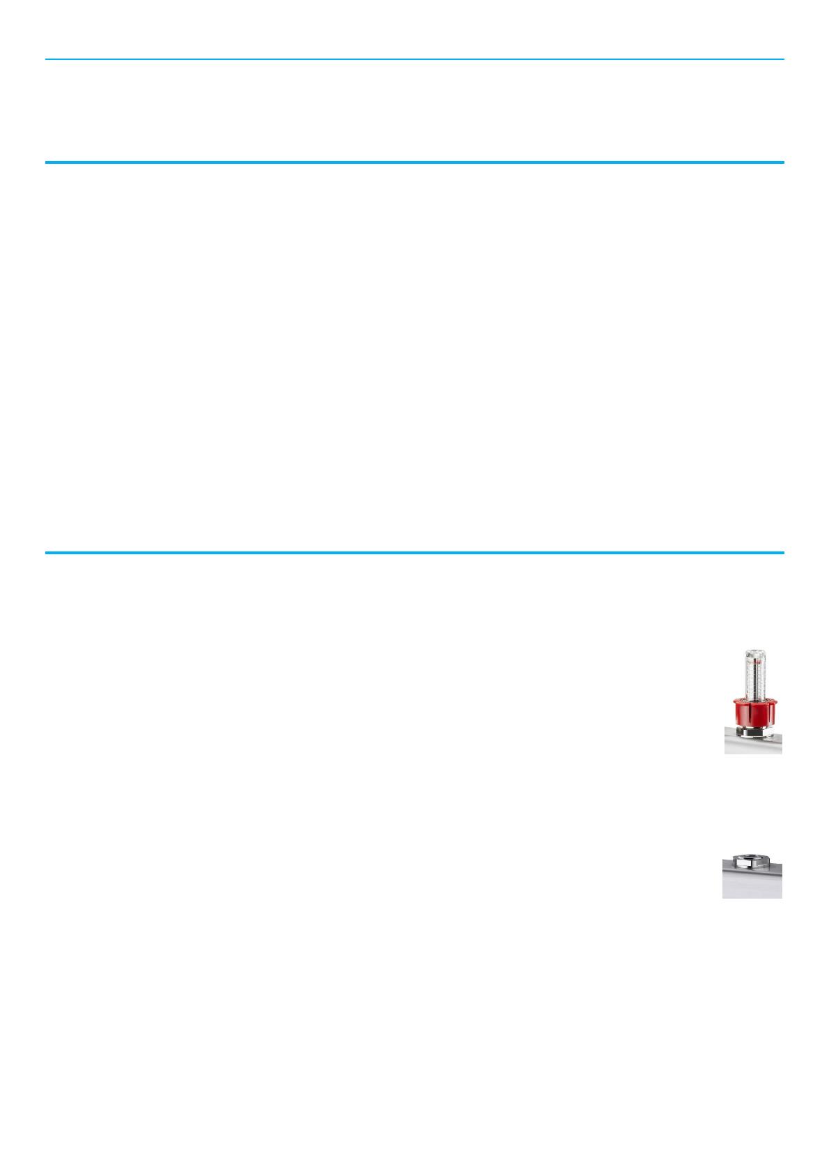
WITH FLOW MEASURING AND REGULATIN DEVICES (ITEM NO. 14063)
Each heating circuit is set by adjusting the flow measuring and regulating devices. The setting range is 0 to 5 litres
per minute. During setting, the circulation pump does not have to be in operation and, if necessary, set to constant
speed operating mode. The setting should be done before the actuators are mounted. If actuators are already
mounted, they should be removed. If this is not possible, make sure that all actuators are in the fully open position.
WITH REGULATING INSERTS (ITEM NO. 14065)
Each heating circuit is set by throttling the regulating inserts. When designing with OVplan, the set values are determined in the
calculation and can be adopted directly. The set value is given in counterclockwise turns from the closed position of the
regulating insert. Presetting 2 therefore corresponds to two full turns.
Alternatively, the set value can be determined from the pressure loss chart at the end of this data sheet. Flow rate
and pressure loss are required to determine the set value. The point of intersection of the two values in the chart
corresponds to the preset value. Setting of the regulating inserts can be carried out at any time.
Product Data Multidis SF
Subject to changes All rights reserved EN-02101-14063-DB-V2319 4
Dimensions and Item Numbers
Multidis SF with flow measuring and regulating devices (item no. 14063)
Number of heating
circuits Length (L) Item no.
2188 mm 1406352
3238 mm 1406353
4288 mm 1406354
5338 mm 1406355
6388mm 1406356
7438 mm 1406357
8488 mm 1406358
9538 mm 1406359
10 588 mm 1406360
11 638 mm 1406361
12 688 mm 1406362
Multidis SF with regulating inserts (item no. 14065)
Number of heating
circuits Length (L) Item no.
2188 mm 1406552
3238 mm 1406553
4288 mm 1406554
5338 mm 1406555
6388mm 1406556
7438 mm 1406657
8488 mm 1406658
9538 mm 1406559
10 588 mm 1406560
11 638 mm 1406561
12 688 mm 1406562
Additional lengths for shutoff ball valves
Item no. ball valve Nominal size Additional length L1
1406383 DN 20 55 mm
1406384 DN 25 80 mm
1406483 DN 20 73 mm
1406484 DN 25 85 mm
1406583 DN 20 73 mm
1406584 DN 25 85 mm
Product Data Multidis SF
Subject to changes All rights reserved EN-02101-14063-DB-V2319 5
Accessories
Ball valves
Size Suitable for Item no.
Ball valve, flat sealing, with red
T-handle DN 20: G ¾ x G 1All Multidis SF 1406383
DN 25: G 1 x G 1All Multidis SF 1406384
Ball valve, flat sealing with red
T-handle and thermometer DN 20: G ¾ x G 1All Multidis SF 1406483
DN 25: G 1 x G 1All Multidis SF 1406484
Ball valve, flat sealing, with blue
T-handle and thermometer DN 20: G ¾ x G 1All Multidis SF 1406583
DN 25: G 1 x G 1All Multidis SF 1406584
Surface
-
mounted cabinet
No. Inner width Item no
Steel, galvanised. Frame and door
white lacquered.
Depth surface-mounted element:
160 mm
Height surface-mounted element:
760870 mm
No. 1600 mm 1401171
No. 2750 mm 1401172
No. 31,000 mm 1401173
No. 41,250 mm 1401174
-
mounted cabinet
No. Inner width Item no.
Steel, galvanised. Frame and door
white lacquered. With removable
screen.
Depth flush-mounted element:
115180 mm
Height flush-mounted element:
760885 mm
No. 1560 mm 1401151
No. 2700 mm 1401152
No. 3900 mm 1401153
No. 41,200 mm 1401154
Compression fittings
For pipe Item no.
Cofit S compression fitting for Copipe multi-layer
composite pipes and plastic pipes
according to DIN EN 16313, clamping ring and union nut
made of brass, union nut nickel-plated, outlet made of
bronze, metal to metal sealing plus O-Ring
2-fold for G ¾ external thread
14 x 2 mm 1507934
16 x 2 mm 1507935
17 x 2 mm 1507937
18 x 2 mm 1507938
20 x 2 mm 1507939
20 x 2,5 mm 1507940
Ofix K compression fitting for plastic pipes
according to DIN EN 4726, PE-X according to
DIN 16892/16893, PB according to DIN16968 and PP
according to DIN 8078 A1,
metal to metal sealing plus O-Ring
2-fold, for G ¾ external thread
12 x 2 mm 1016870
14 x 2 mm 1016873
16 x 2 mm 1016874
17 x 2 mm 1016876
18 x 2 mm 1016877
20 x 2 mm 1016879
Product Data Multidis SF
Subject to changes All rights reserved EN-02101-14063-DB-V2319 6
Actuator
Type Cable length Suitable for Item no.
Aktor T thermal actuator, on/off
With fixed cable and stroke position
indicator, IP54, 230 V AC
Normally closed
1m All Multidis SF 1012415
2 m All Multidis SF 1012452
5 m All Multidis SF 1012455
10 m All Multidis SF 1012459
Electrical connecting block
Version Item no.
6 control zones, heating 230 V / 24 V 1400980
10 control zones, heating / cooling (change-over),
pump control 230 V 1400981
24 V 1400982
10 control zones, heating / cooling (change-over), pump and
boiler control and integrated time switch 230 V 1400983
Electrical connecting blocks with adaptive hydronic balancing
Version Item no.
FloorCon F 200
8 control zones / 12 heating circuit, pump control heating
and cooling (change-over), 230 V
Without channel
allocation 1400984
FloorCon F 300
8 control zones / 12 heating circuits, pump control heating
and cooling (change-over), 230 V
With channel
allocation 1400985
Return temperature sensor
Must be ordered in addition to FloorCon. The temperature
sensor is required 1x per heating circuit. Suitable for pipe
Ø1220 mm
Length 0.85 meter 1029094
Length 2.1 Meter 1029095
Product Data Multidis SF
Subject to changes All rights reserved EN-02101-14063-DB-V2319 7
Spare parts
Multidis SF with flow measuring and regulating devices (item no. 14063)
Pos. Article Item no.
2Flow measuring and regulating device,
05 l/min 1408038
3Fill and drain cock G ¾ 1408104
4Connection nipple, long 1408129
6Valve insert 1404091
8Connection nipple, short 1408126
10 Wall bracket 1408110
Multidis SF with regulating inserts (item no. 14065)
Pos. Article Item no.
2Regulating insert 1408122
3Fill and drain cock G ¾ 1408104
4Connection nipple, short 1408126
6Valve insert 1404091
9Wall bracket 1408110
Product Data Multidis SF
Subject to changes • All rights reserved © 2022 Oventrop GmbH & Co. KG
EN-02101-14063-DB-V2319 – May 2023
Oventrop GmbH & Co. KG Paul-Oventrop-Stre 1 59939 Olsberg Germany
T +49 2962 820 mail@oventrop.com www.oventrop.com
Design
Multidis SF with regulating inserts (item no. 14065)
Flow chart
Pressure loss [kPa]
Flow rate [l/h]
Kv values
Presetting 11,522,533,544,55Kvs
Kv value 0.13 0.19 0.21 0.31 0.63 0.95 1.2 1.55 1.8 1.9
1
1
1
1,5
1,5
1,5
2
2
2
2,5
2,5
2,5
3
3
3
3,5
3,5
3,5
4
4
4
4,5
4,5
4,5
5
5
5
1
10
100
10 100 1.000
  • Page 1 1
  • Page 2 2
  • Page 3 3
  • Page 4 4
  • Page 5 5
  • Page 6 6
  • Page 7 7
  • Page 8 8

Oventrop 1406553 Datasheet

Type
Datasheet

Ask a question and I''ll find the answer in the document

Finding information in a document is now easier with AI