LG LSUQ12YNYA Owner's manual

Type
Owner's manual
1
2
3
4
5
AIR CONDITIONER INSTALLATION MANUAL
TYPE: WALL MOUNTED
EN English
REFRIGERANT
MFL69733044
Rev.02_061418
SAFETY INSTRUCTIONS
The following safety guidelines are intended to prevent unforeseen risks or damage from unsafe or incorrect operation of the appliance.
The guidelines are separated into ‘WARNING’ and ‘CAUTION’ as described below.
This symbol is displayed to indicate matters and operations that can cause risk. Read the part with this symbol carefully and follow the
instructions in order to avoid risk.
WARNING
This indicates that the failure to follow the instructions can cause serious injury or death.
CAUTION
This indicates that the failure to follow the instructions can cause the minor injury or damage to the product.
IMPORTANT SAFETY INSTRUCTIONS
WARNING
To reduce the risk of explosion, fire, death, electric shock, injury or scalding to persons when using this product, follow basic precautions, including
the following:
The information contained in the manual is intended for use by a qualified service technician who is familiar with the safety procedures and equipped with the proper tools and test
instruments.
The appliance shall be installed in accordance with national wiring regulations.
Compliance with national gas regulations shall be observed.
Means for disconnection must be incorporated in the fixed wiring in accordance with the wiring rules.
If the supply cord is damaged, it must be replaced by the manufacturer, its service agent or similarly qualified person in order to avoid a hazard.
Appliance shall be disconnected from its power source during service and when replacing parts.
Failure to read and follow all instructions in this manual can result in equipment malfunction, property damage, personal injury and/or death.
Check that the appliance’s voltage level is 90 % or higher than the rated voltage. To check it, refer to the label attached to the side of the appliance.
Do not install the appliance on an unstable surface or in a place where there is danger of it falling.
This appliance must be grounded. In the event of malfunction or breakdown, grounding will reduce the risk of electric shock by providing a path of least resistance for electric current.
Improper connection of the equipment-grounding conductor can result in risk of electric shock. Check with a qualified electrician or service personnel if you are in doubt as to whether the
appliance is properly grounded.
If the power supply cable is damaged or the cable connection is loose, do not use the power supply cable and contact an authorized service center.
Do not connect the ground wire to a gas pipe, a lightning rod, or a telephone ground wire.
Do not share the power supply for this unit with other appliances or devices, it must be a dedicated power source for this appliance.
Do not modify or extend the power cable.
Ensure the power cable is secure so that it does not come out while the appliance is operating.
Do not touch the power plug or the appliance controls with wet hands.
Cut the power during a severe thunderstorm or lightening or when not in use for a long period of time.
Do not grab the power cable when removing the plug, but rather hold the power plug tightly.
Do not bend the power cable excessively or place a heavy object on it.
Do not turn on the circuit breaker or power when covers are removed or opened.
Make sure that the pipe and the power cable connecting the indoor and outdoor units are not pulled too tight when installing the appliance.
Install dedicated electric outlet and circuit breaker for the appliance.
Make sure to close the cover of the control box after connecting the wiring to the appliance.
Loose connections may cause electrical sparks, injury, and death.
Do not install the appliance in a place where flammable liquids or gases such as gasoline, propane, paint thinner, etc., are stored.
Only use the refrigerant designated on the label, do not put any foreign substances into the appliance.
Any person who is involved with working on or breaking into a refrigerant circuit should hold a current valid certificate from an industry-accredited assessment authority regard of
flammable refrigerants, which authorizes their competence to handle refrigerants safely in accordance with an industry recognized assessment specification.
Servicing shall only be performed as recommended by the equipment manufacturer. Maintenance and repair requiring the assistance of other skilled personnel shall be carried out under
the supervision of the person competent in the use of flammable refrigerants.
Keep any required ventilation openings clear of obstruction.
Refrigerant tubing shall be protected or enclosed to avoid damage.
Flexible refrigerant connectors (such as connecting lines between the indoor and outdoor unit) that may be displaced during normal operations shall be protected against mechanical
damage.
Mechanical connections (mechanical connectors or flared joints) shall be accessible for maintenance purposes.
A brazed, welded, or mechanical connection shall be made before opening the valves to permit refrigerant to flow between the refrigerating system parts.
Use non-flammable gas (nitrogen) to check for leak and to purge air.
Use only refrigerant grade pipe specific for R32 refrigerant. Do Not Use R22 products, which have lower pressure ratings and can result in excessive pressure, explosion and injury.
Inert gas (oxygen free nitrogen) should be used when you checking for leaks, cleaning or repairs of pipes etc. If you are using combustible gases including oxygen, appliance may have
the risk of fires and explosions.
Do not use copper pipes which are deformed. Otherwise, the expansion valve or capillary tube may become blocked with contaminants.
Ducts connected to an appliance shall not contain an ignition source.
The installation of pipe-work shall be kept to a minimum.
When installing or relocating the appliance, consult with a qualified technician to set up the appliance. The appliance should not be installed by someone without proper qualifications.
Operating the appliance while it is disconnected to the pipe could result in explosion and damage. Use the appliance after connecting it to the pipe once the appliance has been
relocated and the refrigerant circuit repaired.
Do not place a heater or other heating appliances near the power cable.
CAUTION
To reduce the risk of minor injury to persons, malfunction, or damage to the product or property when using this product, follow basic precautions,
including the following:
Install at places where it can endure the weight and vibration/noise of the outdoor unit.
Install the appliance in a place where the noise from the outdoor unit or the exhaust air will not inconvenience the neighbors. Failure to do so may result in conflict with the neighbors.
Ensure the appliance is installed level. Otherwise, it may cause vibration or water leakage.
Install the drain hose properly for the smooth drainage of water condensation.
Do not touch the leaking refrigerant during installation or repair.
Do not discharge the refrigerant into the atmosphere.
If refrigerant leaks, ventilate the room.
Always check for gas (refrigerant) leakage after installation or repair of appliance.
Be cautious not to get injured by the sharp edges while installing the appliance or taking it out of its packaging.
Ensure that you carry by the chassis when you lift the unit.
This appliance should only be transported by two or more people holding the appliance securely.
Safely dispose of packing materials such as screws, nails or batteries using proper packaging after installation or repair.
To avoid nitrogen entering the refrigerant system in a liquid state, the top of the cylinder must be higher than its bottom when you pressurize the system.
The tubing shall be protected to the extent that it will not be handled or used for carrying during moving of the appliance.
Ventilation system have to be installed in the space when appliance with R32 is using for cooling of electric equipment.
Do not use the appliance for special purposes, such as preserving foods, works of art, and etc. It is an appliance for consumer purposes, not a precision refrigerant system. There is risk
of damage or loss of property.
Installation Tools
Phillips Screwdriver Standard Screwdriver Electrical Drill Hole Core Drill
Adjustable Wrench Torque Wrench Spirit Level Tape Measure
Tube Cutter Tube Expander Reamer Cutting Knife
Hexagon Wrench Thermometer Gas Leak Detector
(R32)
Current Meter
Lo Hi
Manifold Gauge
(R32)
Vacuum Pump
(R32)
Reclaim Unit
(R32)
Ventilation Equipment
(R32)
NOTE
Leakage detector which is confirmed rated for use with R32, should be used when you are
checking for leaks.
Under no circumstances shall potential sources of ignition be used in the searching for or
detection of refrigerant leaks. A halide torch (or any other detector using a naked flame) shall not
be used.
Ventilation Equipment: For AC system using R32 (A2L gases) a ventilation equipment with “Ex”
mark only should be used when a system design exceeds the Lower Flammable Limit if the gas
was to escape from a system.
INSTALLATION PLACE
Indoor Unit
Install the indoor unit on a strong and hard
wall.
Install the indoor unit in a spot with good
drainage and good accessibility to the pipe
connected to the outdoor unit.
Maintain a clearance of at least 100 mm
from the right and left sides of the indoor
unit.
Maintain a clearance of at least 200 mm
between the top of the indoor unit and the
ceiling.
200
100
100
Unit: mm
NOTE
Do not install the indoor unit near heaters or
heating apparatuses.
Do not install the indoor unit near an
obstacle that hinders airflow.
Do not install the indoor unit near an exit.
Do not install the indoor unit where it can be
exposed to direct sunlight.
Outdoor Unit
Install the outdoor unit in a location where
the floor is firm and even.
Install the outdoor unit where hot wind or
noise will not disturb neighbor.
Install the outdoor unit somewhere the
technician can easily access it for repairs or
maintenance.
Maintain a clearance of 300 mm from the
left and the back(air inlet) sides and 600 mm
from the right sides of the outdoor unit.
If there is an obstacle in front of the air vent,
keep the outdoor unit at a distance of at
least 700 mm from the obstacle.
300
700
300
600
Unit: mm
NOTE
Do not install the outdoor unit where a
location is unstable or may vibrate.
Do not install the outdoor unit in a location
exposed to saline conditions, such as
coastal areas, or sulfuric steam, such as
near a hot spring.
Do not install the outdoor unit in a location
exposed to high winds.
Do not install the outdoor unit somewhere
exposed to direct sunlight. (Otherwise, make
sure to put up a protective awning.)
Do not keep any animals or plants near the
air vent.
Precautions for Installation in
Coastal Areas
Do not install the appliance in an area
where it is directly exposed to sea air (salt
spray).
Saline conditions are a cause of corrosion.
(Particularly, corrosion of the condenser
and evaporator can damage the appliance
or impair its performance.)
Set up windbreak in front of the outdoor unit
if installing it in coastal areas.
Avoid direct exposure to salt winds.
Install a firm and stiff concrete-wind shield
that can withstand salt winds.
NOTE
If you have to set up the outdoor unit in a
coastal area, unless the installation
conditions are able to satisfy the above
precautions, call an LG Electronics
Customer Service Center to find out about
alternatives.
Precautions for Installation in
Special Regions (Snowfall,
Strong Winds, Area with
Severely Cold or Humid
Weather)
Install the outdoor unit where the airflow
fans are protected from being buried under
snow. Accumulated snow could cause the
device to malfunction by clogging the airflow.
Install the outdoor unit on a platform at least
500 mm above the ground where a location
has heavier snowfall than the annual
average. (The size of the platform should
correspond with the size of the outdoor unit.
If the platform is wider or longer than the
outdoor unit, snow may accumulate.)
Put a snow-protective cover on the outdoor
unit.
Place the inlet and outlet for the outdoor unit
in opposite directions to direct airflow and to
prevent snow and rain from flowing into the
equipment.
Install the outdoor unit in a spot that is well
lit and well ventilated in highly humid areas
(near sea or fresh water bodies).
Refrigerant (for R32 Only)
WARNING
The appliance shall be stored in a
well-ventilated area where the room size
corresponds to the room area as specified
for operation.
The appliance shall be stored in a room
without continuously operating open flames
(for example an operating gas appliance)
and ignition sources (for example an
operating electric heater).
The appliance shall be stored so as to
prevent mechanical damage from occurring.
Do not use means to accelerate the
defrosting process or to clean, other than
those recommended by the manufacturer.
Do not pierce or burn.
Be aware that refrigerants may not contain
an odour.
Pipe-work shall be protected from physical
damage and shall not be installed in an
unventilated space, if that space is smaller
than the minimum floor area.
Minimum Floor Area
Refer the minimum floor area depending on
the installation height. If outdoor units are
installed indoors, outdoor units also meet the
minimum floor area.
m (kg)
Minimum Floor Area (m
2
)
Floor
Standing
Wall
Mounted
Ceiling
Mounted
< 1.224 - - -
1.224 12.90 1.43 0.956
1.2 12.36 1.37 0.92
1.4 16.82 1.87 1.25
1.6 21.97 2.44 1.63
1.8 27.80 3.09 2.07
2.0 34.32 3.81 2.55
2.2 41.53 4.61 3.09
2.4 49.42 5.49 3.68
m: Total refrigerant amount in the system
Total refrigerant amount: Factory refrigerant
charge + Additional refrigerant amount
NOTE
The actual refrigerant charge is in
accordance with the room size within which
the refrigerant containing parts are installed.
The ventilation machinery and outlets are
operating adequately and are not obstructed.
If an indirect refrigerating circuit is being
used, the secondary circuit shall be checked
for the presence of refrigerant.
Marking to the equipment continues to be
visible and legible. Markings and signs that
are illegible shall be corrected.
Refrigeration pipe or components are
installed in a position where they are unlikely
to be exposed to any substance which may
corrode refrigerant containing components,
unless the components are constructed of
materials which are inherently resistant to
being corroded or are suitably protected
against being so corroded.
PREPARATION WORK
Fixing the Installation
Plate
To securely fasten the indoor unit, fix the
installation plate onto a wall.
1
Separate the installation plate equipped
on the back of the indoor unit.
2
Confirm the location where you will place
the installation plate.
Choose a strong and hard wall that can
withstand the weight of the indoor unit.
3
Securely fix the installation plate onto the
wall with type ‘A’ screws.
Tighten a screw into the center hole ( )
of the installation plate.
Ensure the installation plate is horizontal
using a spirit level.
Tighten the remaining screws into the
holes indicated by the arrow on the
installation plate.
NOTE
If installing the installation plate onto a weak
or insufficiently hard wall, utilize an anchor
bolt.
If the installation plate is set unevenly, water
may not drain smoothly and result in
leakage into the room.
Making a Hole in the Wall
Put a hole into the wall to connect the power
cable, drain hose, and pipes attaching the
indoor device to the outdoor one.
1
Confirm the location of the hole you are
going to add.
Measure the distance from the
installation plate.
Refer to the measure indicated on the
installation plate.
a c
b d
Framework of Indoor Unit
Unit: mm
Type A-1 Type A-2 Type B
a 98 76 84
b 152 113 136
c 134 134 84
d 194 178 145
2
Make a hole in the wall by Ø 65 mm hole
core drill.
To facilitate drainage flow, drill the hole
at an oblique angle from the inside
going outside. (The inclination of the
hole could be different depending on the
specific conditions.)
Indoor Outdoor
Preparing the Pipe and
Power Cable
Once the gap between the indoor unit and the
outdoor unit one has been measured, cut the
pipe and power cable to the proper length.
Cut the pipe slightly longer that the
measurement.
Cut the power cable 1.5 m longer than the
pipe.
NOTE
If you purchase the pipe separately, do not
use thinner pipe than the specified value.
Use the deoxidised copper as piping
materials to install.
Flare Work
Flaring must be performed accurately to
prevent any gas leakage.
1
Cut the pipe with a copper tube cutter.
90
2
Remove the burrs using a reamer.
Hold the edge of the cut pipe so it is
pointing downward and remove the
burrs. This helps prevent metal powder
from getting into the pipe.
3
Put the flare nut onto the pipe (burr is
removed).
4
After inserting the pipe into the tube
expander, begin flaring.
As seen in diagram “a”, put the pipe
slightly above the upper side of the Bar.
a
<Wing Nut> <Clutch>
Pipe Size
a
(Wing
Nut)
Thickness
mm inch mm mm
Ø 6.35 Ø 1/4 1.1~1.3 0.7
Ø 9.52 Ø 3/8 1.5~1.7 0.8
Ø 12.70 Ø 1/2 1.6~1.8 0.8
Ø 15.88 Ø 5/8 1.6~1.8 1.0
NOTE
a (Clutch): 0.0~0.5 mm
Temper grade of pipe: Annealed
5
Check out the condition of the flare.
Check that the flared section of the pipe
(1) was flared evenly in its curved
surface and thickness.
Make sure all flared surfaces (2) have
been flared smoothly.
Example of Correct Flaring
(1) (1)
(2)
Example of Incorrect Flaring
NOTE
If the expanded pipe has tilting, surface
damage, cracks, or a thickness imbalance,
perform the flaring operation again.
When flared joints are reused indoors, the
flare part shall be re-fabricated.
INSTALLING THE INDOOR UNIT
Bending the Pipe
1
Pull out the decor at the bottom of the
indoor unit.
Hold the center of the decor (1) and pull
it towards you. Then, pull both sides of
the decor out (2).
(1)
(1)
(2)
(2)
Position of Hooks
NOTE
The quantity and position of the hooks
could be different depending on models.
2
Open the tubing holder at the back of the
indoor unit.
3
After straightening the pipe gradually
downward, bend it to the direction to be
installed.
Correct Example of Bending the Pipe
Incorrect Example of Bending the Pipe
NOTE
The pipe can be damaged if you bend it
directly from right to left.
Connecting the Drain
Hose
1
Remove the drain cap where you are
going to connect the drain hose.
If you do not use the other drain hose
hole, block it with a drain cap.
2
Insert the drain hose.
Extending the Drain Hose
1
Insert the extending hose into the drain
hose joint.
2
Wrap the joint area with vinyl tape at least
10 times.
NOTE
The indoor extended drain hose should be
wrapped in insulation to decrease the
amount of leakage. You can purchase
insulation material separately.
Installing the Indoor Unit
on the Installation Plate
Put the indoor unit onto the installation plate
fixed on the wall.
Check if the hook on top of the rear part of
the indoor unit is securely fastened onto the
installation plate.
PRODUCT OVERVIEW
NOTE
The feature may be changed according to the type of model.
Parts
Installation Plate
Air Filter
Decor
Gas Pipe (Larger Pipe)
Liquid Pipe (Smaller Pipe)
Drain Hose
Power Supply Cable
Gas Service Valve
Liquid Service Valve
This feature could be different depending on models.
(Gas/Liquid) Service Valve Cap
NOTE
If needed, additional pipes, drain hoses, and power cables must be purchased separately.
When mechanical connectors are reused indoors, sealing parts shall be renewed.
Local Purchases
It is highly recommended that you install the following parts:
Sleeve
Sealant
Clamp
Installation Parts
Installation Plate
(Type A-1)
Installation Plate
(Type A-2)
Installation Plate
(Type B)
Remote Control
Holder
Type 'A' Screws
(for Installation Plate)
Type 'B' Screws
(for Remote Control
Holder)
Type 'C' Screws
(for Chassis)
Vinyl Tape (PVC) Tie Wrap
1
2
3
4
5
6
7
8
9
10
A
B
C
6
7
8
9
10
11
12
13
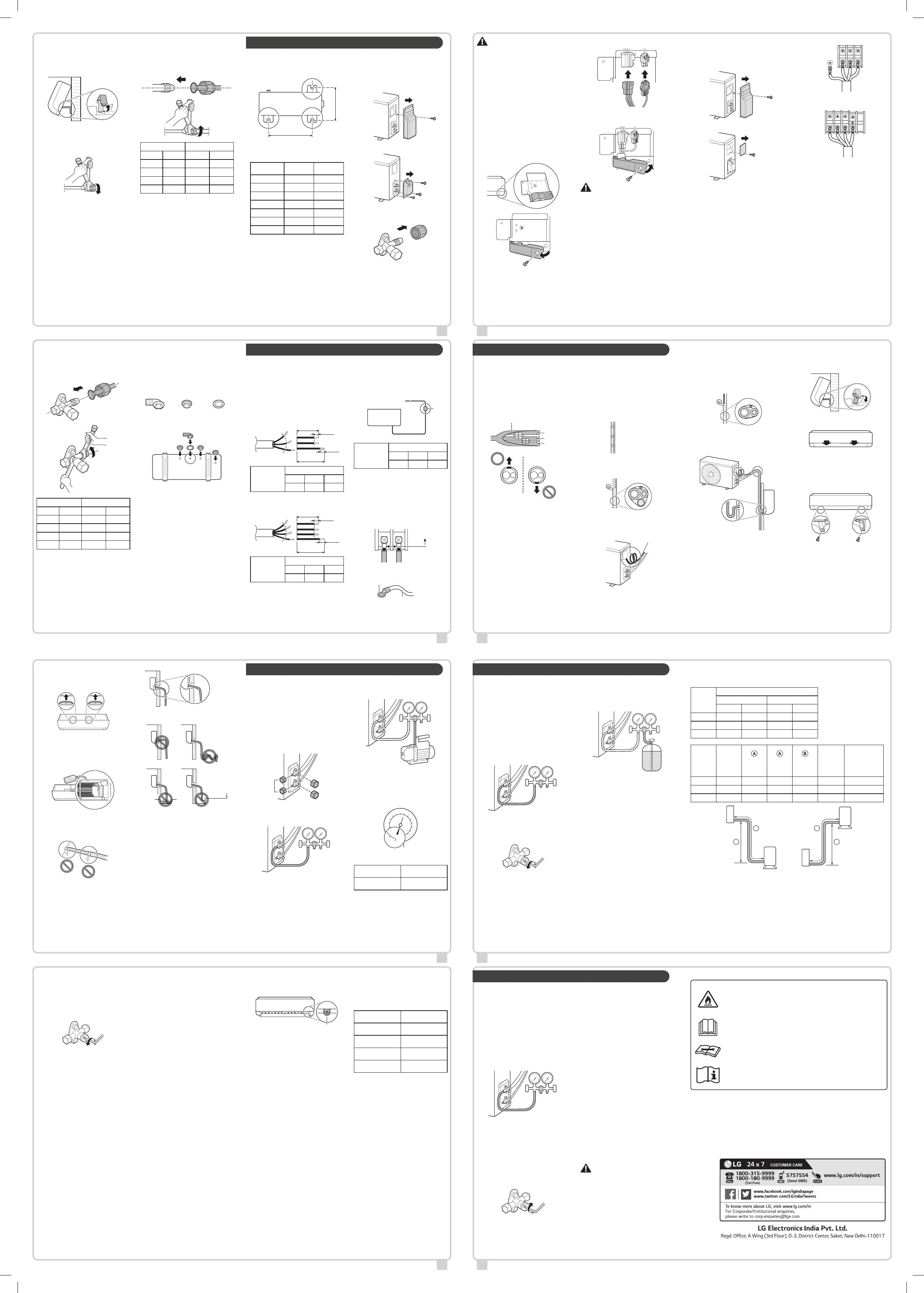
Connecting the Indoor
Unit Pipe
1
By reclining the tubing holder, make a
space between the bottom of the indoor
unit and the wall.
2
Remove each of the flare nuts attached to
the pipes of the indoor unit.
First, secure the pipe with an adjustable
wrench and then, loosen the flare nut
using a torque wrench.
3
Tighten the flare nut after inserting the
pipe engaged with the flare nut through
the center of the indoor unit's pipe.
After fixing the pipe with the help an
adjustable wrench, securely tighten the
flare nut using a torque wrench.
Pipe Size Torque
mm inch kgf•cm N•m
Ø 6.35 Ø 1/4 180~250 17.6~24.5
Ø 9.52 Ø 3/8 340~420 33.3~41.2
Ø 12.70 Ø 1/2 550~660 53.9~64.7
Ø 15.88 Ø 5/8 630~820 61.7~80.4
NOTE
To prevent gas leakage, apply refrigeration
oil on both inner and outer surfaces of the
flare.
INSTALLING THE OUTDOOR UNIT
Fixing the Outdoor Unit
Fix the outdoor unit firmly to prevent it from
falling and dropping.
a
b
Refer to the measurements for “a” and “b”,
depending on the type of chassis. (Chassis
type is marked inside the top of the outdoor
unit packing box.)
Name of
Chassis
a (mm) b (mm)
UA3 463 256
UL 519 267
UL2 558 329
UE 546 340
UE1 546 340
U24A 586 366
U4 620 360
NOTE
If you install the outdoor unit on a wall, roof,
or rooftop, make sure it's mounted on a
suitable frame.
If the outdoor unit vibrates excessively,
secure it using anti-vibration rubber between
the unit's feet and the mounting frame.
Connecting the Outdoor
Unit Pipe
1
Open the tubing cover.
Type 1
Type 2
2
Remove each of the flare nuts attached to
the valves of the outdoor unit.
3
Tighten the flare nut after inserting the
pipe engaged with the flare nut through
the center of the outdoor unit's valve.
After fixing the valve with the help an
adjustable wrench, securely tighten the
flare nut using a torque wrench.
Pipe Size Torque
mm inch kgf•cm N•m
Ø 6.35 Ø 1/4 180~250 17.6~24.5
Ø 9.52 Ø 3/8 340~420 33.3~41.2
Ø 12.70 Ø 1/2 550~660 53.9~64.7
Ø 15.88 Ø 5/8 630~820 61.7~80.4
NOTE
To prevent gas leakage, apply refrigeration
oil on both inner and outer surfaces of the
flare.
Connecting the Drain Plug
If you need to install a drain hose onto an
outdoor unit, connect the drain hose after
inserting the drain plug with drain washer
through the drain hole on the bottom of the
outdoor unit.
Accessories
Drain Plug Drain Cap Drain Washer
NOTE
If the hole is not in use, block it with the
drain cap.
The quantity and position of the drain cap
could be different depending on models.
In cold areas, do not use the drain hose on
the outdoor unit because the water drained
out from the drain hose can freeze, which
may cause malfunctioning by damaging the
heat exchanger.
CONNECTING THE POWER CABLE
All power wiring/communication cables must
comply with applicable local and national
codes.
The cable specification for outdoor use shall
not be less than polychloroprene sheathed
flexible cord.
The earth wire should be longer than the
common wires.
Power Supply Cable
GN/YL
65±5
45±5
10±3
10±3
GN/YL
Unit: mm
Nominal Cross
Sectional Area
(Minimum)
Capacity (kBtu/h)
12 18 24
1.0 mm
2
1.5 mm
2
2.5 mm
2
Inter-Connecting Cable
GN/YL
45±5
10±3
65±5
10±3
GN/YL
Unit: mm
Nominal Cross
Sectional Area
(Minimum)
Capacity (kBtu/h)
12 18 24
1.0 mm
2
1.5 mm
2
2.5 mm
2
NOTE
Cable provided by LG can be different from
above figures. Please modify the cables
comply with above figures.
Some models do not provide cables.
Circuit Breaker
Between the power and the appliance, install a
certified circuit breaker. The interrupting device
should be equipped to properly block all power
sources.
Air
Conditioner
Main Power Source
Circuit
Breaker
Circuit Breaker
Capacity (kBtu/h)
12 18 24
15 A 20 A 25 A
NOTE
Check whether the current capacity of the
selected cable and wiring exceeds the rated
capacity of the recommended circuit
breaker.
Connecting the Wires
The distance between wires should be more
than 5 mm.
5 mm
Connect the wire after inserting the circular
terminal.
Circular Terminal
Wire
CAUTION
Without exception, install an independent
power circuit specifically designed for the
appliance. Refer to the circuit diagram
attached inside the control cover for where
to connect the cable.
Screw connections in the appliance’s control
box can vibrate loose during transporting
and operating the appliance. Check that all
the connections in the appliance are
securely fixed at all times. (If they have
loosened, both the wire and the termination
can be broken.)
NOTE
Circuit diagrams may be altered by the
manufacturer without any notification.
Indoor Unit
1
Open the clamp cord.
2
Connect the connecting cables.
3
Close the clamp cord again and secure it
with a screw.
CAUTION
Loose screws may cause electrical sparks,
injury, and death.
NOTE
The feature may be changed according to
the type of model.
Outdoor Unit
1
Open the tubing cover (Type 1) or the
control cover (Type 2).
Type 1
Type 2
2
Open the clamp cord.
3
After pairing both the wires and the
ground wire with the terminal block, fasten
them securely by tightening the screws.
The color of the wire for the outdoor unit
and the terminal number should be the
same as that of the indoor unit.
Type 1
1(L) 2(N) 3(C)
Inter-Connecting Cable
Type 2
1(L) 2(N) 3(C)
Inter-Connecting Cable
4
Close the clamp cord again and secure it
with a screw.
5
After closing the tubing cover or control
cover, secure them with screw.
FINALIZING INSTALLATION
Wrap of Pipe Connection
with Insulation
Bind the pipe connecting area with insulator
and securely tie with vinyl tape.
Wrap up the pipes with insulator to prevent
gaps between them.
Make the cutting line of the insulator
wrapping the pipe face the upper direction.
Cut Line
Wrapping Up the Pipe,
Drain Hose, and Power
Cable
If the Outdoor Unit is Placed Below the
Indoor Unit
1
Partially tie up the overlapping lines of
pipe, drain hose, and power cable using
thin vinyl tape.
2
Use wide vinyl tape to fully tie up all the
lines (pipe, drain hose, and power cable).
Start winding from the bottom up.
3
Trap the power cable.
This can prevent the electrical
components from coming into contact
with water.
4
Close the tubing cover.
If the Outdoor Unit is Above the Indoor Unit
1
Partially tie up the overlapping lines of
pipe, and power cable using thin vinyl
tape.
2
Use wide vinyl tape to fully tie up all the
lines (pipe, and power cable).
Start winding from the bottom up.
3
Trap both the pipe and the power cable.
This can prevent the room and the
electrical components from coming into
contact with water.
4
Close the tubing cover.
NOTE
Apply sealant around the pipe going through
the hole in the wall. This sealant can prevent
the indoor air from being contaminated by
outdoor air and foreign substances.
Finalizing the Indoor Unit
Installation
1
Close the tubing holder.
2
Push both sides (right and left) of the
indoor unit toward the installation plate.
3
Fix the indoor unit on the installation plate
using ‘C’ type screws.
Unless the indoor unit is fixed onto the
installation plate securely, it may fall.
Tighten the screws firmly to avoid a gap
between the indoor unit and the
installation plate.
4
Reassemble the separated decor to the
indoor unit.
Checking the Drainage
1
Remove the filter.
Pull the filter up and out towards you.
NOTE
Do not touch the metal part of the
appliance when removing the filter.
2
Pour a cup of water into the back of the
evaporator.
3
Check the drainage condition.
Check whether there is any leakage
from either the drain hose joint or the
extended hose joint.
Check the water is flowing out through
the drain hose.
NOTE
If there is no leakage, but no water is
flowing, pour a proper amount of water
again.
4
Insert the filter again.
Example of Correct Drain Hose Installation
Example of Incorrect Drain Hose
Installation
50 mm
NOTE
If the drain hose is not installed properly,
water can leak indoors.
If the drain hose is installed at a higher
position than the indoor unit
If the drain hose is entangled or kinked
If the end of the drain hose is dipped in
water
If the gap between the end of the drain
hose and the bottom is lower than 50 mm
CHECK AFTER INSTALLATION
Vacuum
Residual air or vapor in the refrigerant system
can lower appliance performance. To increase
cooling and heating performance, remove air
or vapor remaining in the refrigerant system
using the vacuum pump.
Work the vacuuming through the gas service
valve (larger pipe).
1
Remove the caps from the gas service
valve (1), the liquid service valve (2), and
the core valves (3) in the outdoor unit.
(1)
(2)
(3)
2
Connect the low-pressure hose of the
manifold gauge to the core valve of the
gas service valve.
Lo Hi
3
Connect the charging hose of the manifold
gauge to the vacuum pump.
Lo Hi
4
Open the low-pressure valve of the
manifold gauge, and operate the vacuum
pump.
Operate the vacuuming until the
pressure gauge is at -30 inHg (-76
cmHg).
0
2
0
4
0
6
0
8
0
1
0
0
1
2
0
350
120
The time for vacuuming could be
different depending on pipe lengths.
If the pipe is shorter
than 10 m (33 ft)
If the pipe is longer
than 10 m (33 ft)
Longer than 10
minutes
Longer than 15
minutes
NOTE
Make sure to check for gas leakage unless
the vacuuming works for a long time.
5
After completing the vacuum operation,
close the low-pressure valve of the
manifold gauge.
6
Open fully both the gas service valve and
liquid service valve of the outdoor unit.
Rotate the valves to counter-clockwise
using a hexagon wrench.
Check-Up for Gas Leakage
Gas leakage can damage the appliance’s
performance. Check for gas leakage by
applying soapy water on the outdoor unit pipe
connected to the indoor unit pipe’s joint.
If there is gas leakage, bubbling will occur.
In case of bubbling, check the cause of the
gas leakage.
NOTE
Electronic leak detectors shall be used to
detect flammable refrigerants, but the
sensitivity may not be adequate, or may
need re-calibration. (Detection equipment
shall be calibrated in a refrigerant-free area.)
Leak detection equipment shall be set at a
percentage of the LFL (Lower flammable
limit) of the refrigerant and shall be
calibrated to the refrigerant employed and
the appropriate percentage of gas (25 %
maximum) is confirmed.
Leak detection fluids are suitable for use
with most refrigerants but the use of
detergents containing chlorine shall be
avoided as the chlorine may react with the
refrigerant and corrode the copper
pipe-work.
If a leak is suspected, all naked flames shall
be removed/extinguished.
If a leakage of refrigerant is found which
requires brazing, all of the refrigerant shall
be recovered from the system, or isolated
(by means of shut off valves) in a part of the
system remote from the leak.
Oxygen free nitrogen (OFN) shall be purged
through the system both before and during
the brazing process.
Test-Running
Press the ON/OFF button for 3 to 5 seconds
for test operation.
ON/OFF
NOTE
Make sure that the pipe and the power
cable are connected properly.
For the operating the appliance, check
whether both the gas service valve and the
liquid service valve of the outdoor unit are
fully opened.
The feature and position of the button could
be different depending on models.
Checking the Performance
After operating the appliance for 15-20
minutes, check the list below;
1
Check the pressure of the gas service
valve.
Outdoor Temperature
Pressure of Service
Valve (Gas)
20 °C (68 °F)~
35 °C (95 °F)
8.4~9.5 kgf/cm
2
G
(120~135 psi)
35 °C (95 °F)~
40 °C (104 °F)
9.5~10.5 kgf/cm
2
G
(135~150 psi)
40 °C (104 °F)~
45 °C (113 °F)
10.5~11.6 kgf/cm
2
G
(150~165 psi)
45 °C (113 °F)~
48 °C (118 °F)
11.6~12.3 kgf/cm
2
G
(165~175 psi)
NOTE
If the actual pressure is higher than shown,
the refrigerant system is most likely
overcharged, and charge should be
removed. If the actual pressure are lower
than shown, the refrigerant system is most
likely undercharged, and charge should be
added.
2
Measure the temperature of the inlet and
the outlet of the indoor unit.
A difference of eight degrees Celsius
between the inlet and the outlet
indicates that the cooling performance is
in normal.
3
Separate the low-pressure hose of the
manifold gauge from the outdoor unit.
4
Close the core valve cap of the gas
service valve.
Tighten the core valve cap securely with
an adjustable wrench.
CHARGING THE REFRIGERANT
If the amount of refrigerant level is low, the
appliance would provide low performance.
Charge the refrigerant for proper operation.
Refer to the label attached to the side of the
appliance to confirm the type and amount of
refrigerant.
Charge the refrigerant through the gas
service valve (larger pipe).
Hoses or lines shall be as short as possible
to minimise the amount of refrigerant
contained in them.
1
Connect the low-pressure hose of the
manifold gauge to the core valve of the
gas service valve.
Lo Hi
2
Open both the gas service valve and the
liquid service valve of the outdoor unit.
Rotate the valves to counter-clockwise
using a hexagon wrench.
3
Connect the charging hose of the manifold
gauge to the refrigerant cylinder.
Charge Using the Refrigerant Cylinder with
a Siphon
This is usually applied to R32. Charge the
refrigerant (gas phase) by standing the
refrigerant cylinder.
Lo Hi
4
Charge the refrigerant by adjusting the
low-pressure valve of the manifold gauge.
Refer to 'Suggested Amount of
Refrigerant Charge'.
5
After charging the refrigerant, close the
low-pressure valve of the manifold gauge
and separate the connected low-pressure
hose from the outdoor unit.
NOTE
Ensure that contamination of different
refrigerants does not occur when using
charging equipment.
Extreme care shall be taken not to overfill
the refrigerant system.
Prior to recharging the system it shall be
pressure tested with oxygen free nitrogen
(OFN). The system shall be leak tested on
completion of charging but prior to
commissioning. A follow up leak test shall be
carried out prior to leaving the site.
The handling of the refrigerant must comply
with national regulations.
Suggested Amount of Refrigerant Charge
The amount of supplementary refrigerant can be different based on either appliance capacity or
pipe length. Charge the proper amount of refrigerant based to the reference below.
Capacity
(kBtu/h)
Pipe Size
Gas Liquid
mm inch mm inch
12 Ø 9.52 Ø 3/8 Ø 6.35 Ø 1/4
18 Ø 12.70 Ø 1/2 Ø 6.35 Ø 1/4
24 Ø 15.88 Ø 5/8 Ø 6.35 Ø 1/4
Capacity
(kBtu/h)
Standard
Length
(m)
Maximum
Length
(m)
Minimum
Length
(m)
Maximum
Elevation
(m)
Refrigerant
Charge at
Maximum
Pipe
Length
(kg)
Amount of
Additional
Refrigerant
(g/m)
12 5.0 15 3 7 0.8 10
18 5.0 20 3 10 1.175 15
24 5.0 20 3 10 1.375 15
B B
A A
Indoor Unit
Outdoor Unit Indoor Unit
Outdoor Unit
NOTE
The amount of refrigerant charged is based on the standardized pipe length. If the installed pipe
is longer than the standard length, extra refrigerant needs to be added.
Reliability cannot be guaranteed if the pipe is longer than the maximum length.
It may cause reliability, performance, noise, and vibration problems, if piping limitations are not
met. Ensure there's a minimum piping length, by making loops if necessary, if the indoor unit and
outdoor unit are too close.
PUMP DOWN
In case of appliance relocation and repair of
the refrigerant system, operate the pump down
process that brings the refrigerant from the
indoor unit and pipes it to the outdoor unit to
avoid refrigerant loss.
Operate the pump down process in the
cooling mode.
1
Remove the caps from the gas service
valve, the liquid service valve, and the
core valves in the outdoor unit.
2
Connect the low-pressure hose of the
manifold gauge to the core valve of the
gas service valve.
Lo Hi
3
Operate the appliance in the cooling
mode.
Operate the appliance more than 10
minutes after checking whether the
compressor of the outdoor unit is
operating properly.
4
Close the liquid service valve in the
outdoor unit.
Rotate the valve clockwise using a
hexagon wrench.
5
Close the gas service valve in the outdoor
unit at a pressure of 0.5 kgf/cm
2
(14.2 to
7.1 psi).
Rotate the valve clockwise using a
hexagon wrench.
6
Turn off the appliance.
NOTE
Do not operate the appliance for a long
time. It may cause damage to the
compressor.
7
Separate the low-pressure hose of the
manifold gauge and the pipe connected to
the outdoor unit.
Use a torque wrench and adjustable
wrench.
8
Close the caps from the gas service valve,
the liquid service valve, and the core
valves.
Tighten all the caps by using an
adjustable wrench and torque wrench.
NOTE
Block the outdoor valve by screwing a flare
nut through the pipe after welding the end of
the separated pipe. This can protect the
appliance from air, vapor, and foreign
substances.
WARNING
Operating the appliance while it is
disconnected to the pipe could result in
explosion and damage. Use the appliance
after connecting it to the pipe once the
appliance has been relocated and the
refrigerant circuit repaired.
The following symbols are displayed on indoor and outdoor units.
This symbol indicates that this appliance uses a flammable
refrigerant. If the refrigerant is leaked and exposure to an
external ignition source, there is a risk of fire.
This symbol indicates that the Operation Manual should be
read carefully.
This symbol indicates that a service personnel should be
handling this equipment with reference to the Installation
Manual.
This symbol indicates that information is available such as
the Operating Manual or Installation Manual.
Copyright © 2018 LG Electronics Inc. All Rights Reserved.
  • Page 1 1
  • Page 2 2

LG LSUQ12YNYA Owner's manual

Type
Owner's manual

Ask a question and I''ll find the answer in the document

Finding information in a document is now easier with AI