Page is loading ...

‘R’ ‘R’
3
5
7
2
4
6
8
1
50 (2) 10 ⅜
65 (2½) 10 ⅜
80 (3) 11
7
/
16
100 (4) 11
7
/
16
125 (5) 14
7
/
16
150 (6) 14
7
/
16
200 (8) 16 ⅝
250 (10) 16 ⅝
300 (12) 16 ⅝
350 (14) 16 ⅝
400 (16) 19 ¾
450 (18) 24
15
/
16
500 (20) 19 ¾
600 (24) 19 ¾
KEYSTONE FIGURE 952 KNIFE GATE VALVES
InstallatIon and operatIng manual
© 2017 Emerson. All Rights Reserved.
Storage and installation instructions for DN 50 - 600 (NPS 2 - 24)
Figure 952 knife gate valves
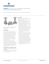
FLANGE BOLTS
CAUTION
It is critical that flange bolts do not bottom out in
valve body otherwise valve damage will occur.
To determine bolt length for the blind holes
in the upper chest area of the valve, add
dimension ‘R’+ gasket + flange thickness + any
washers etc. (plus deflection cone and gasket
when used).
1. Stud bolts can be used in the blind holes in
the chest area of the valve body to alleviate
the risk of flange bolts bottoming out.
2. Coating of flange bolt threads with an
anti-seize compound (Loctite 729 etc.) is
recommended to prevent bolt seizure,
particularly when using S/S bolts with S/S
valves, or when using steel bolts in iron
valves.
STORAGE
Important
Do not remove any identification or instruction
tags. For optimum protection, store valve
undercover.
Valves
Flange faces should be protected at all times
with wooden or heavy cardboard shields.
Oniron bodied valves, lubricate threaded flange
HANDWHEEL OPERATION
On standard valves, turn handwheel anti-
clockwise to open valves, and clockwise to
close valves.
THREAD DEPTHS
Valve size
DN (NPS)
Thread depth
mm inches
GasketGasket
Flange
Valve
Flange
Emerson.com/FinalControl
FIGURE 1
bolt holes to prevent rusting. Apply protective
coating to seating faces of metal to metal
seated valves. Valves should be stored flat
with the flow arrow pointing downwards and in
the closed position, (but not jammed tight) to
protect seating faces and gate from damage.
Handwheel spindle threads should NOT be
lubricated otherwise dirt will accumulate in
threads.
Actuators
All air line and electrical cable entries should
be plugged. If cylinders are not fitted to a valve,
they should be stored with the piston rod fully
retracted. Cylinders are assembled with a light
coating of grease on internal components.
Spare parts
Seats and packings should be carefully stored
and protected from sharp or heavy objects
which will damage sealing faces.
VCIOM-02048-EN 16/02

2
‘R’ ‘R’
3
5
7
2
4
6
8
1
KEYSTONE FIGURE 952 KNIFE GATE VALVES
InstallatIon and operatIng manual
INSTALLATION INSTRUCTIONS
NOTE
Heavy valves will require a chain block or crane to
assist. In difficult locations, large cylinder actuators
can be removed from valve and re-fitted after
installation if necessary, but check cylinder to gate
alignment carefully and that valve seats correctly.
(Refer cylinder fittinginstructions).
1. Close valve.
2. Check valve size is correct and that there is
adequate clearance to install valve.
3. Check flange faces are clean and smooth
and that bolt hole patterns on pipe flanges
are the same as the valve, and are in line.
4. Check bolt sizes and threads are
clean and compatible with the valve.
(Separatetechnical data is available).
5. Check gaskets match flanges and are
suitable for the service.
6. Check that the pipeline, upstream and
downstream, is correctly aligned.
7. If a Deflector cone is being used, fit it to
upstream side of valve with the cone nozzle
pointing downstream, prior to installation.
Metal (Chrome Iron) cones must have
gaskets fitted between the cone and valve,
and between cone and flange. Resilient
urethane cones do not require these
gaskets.
8. Spread flanges to clear valve, check
flow arrow on side of valve is in the right
direction. (Valve seating face and gate are
downstream). Lower valve into position.
Insert gaskets, 1each side.
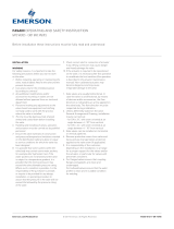
9. Insert flange bolts. On wafer valves, insert
bolts into the threaded bolt holes in the
chest of the valve first but do not tighten
until all bolts are fitted. Tighten bolts in
adiagonal sequence (refer Fig. 2).
10. Ensure bolts in the chest area of the valve
are not bottoming out in the blind holes.
11. Open and close valve to check it is operating
correctly.
12. After pipe line is pressurized, check for
flange leaks and for gland leaks, adjust as
necessary.
PURGE PORTS (WHERE FITTED)
Optional stainless steel purge nozzles can be
fitted in lower part of body. If sedimentation
occurs preventing gate from closing fully, purge
with compressed air or water. Alternatively,
connect permanent installation to purge ports
and purge periodically. Purge port hole is 3 mm
(⅛”)BSPP.
SAFETY
The gland on new and repaired valves may
require final adjustment after installation
and pressurisation of the valve.
Actuated valves are generally operated from a
remote location, caution should be exercised if
working in close proximity to any moving parts.
NOTE
To minimize risk to personnel, Emerson recommend
the use of purpose built guards and shrouds. Refer to
the Emerson data sheet orconsult factory for details.
GLAND ADJUSTMENT
The gland on new and repaired valves may
require final adjustment after installation and
pressurisation of the valve. If packing leaks,
tighten gland nuts equally until leaking ceases.
A 32 mm (1¼”) AF spanner fits DN 50 - 600
(NPS 2 - 24) valve size.
If gland leakage persists, check that pipeline
isnot pressurized above rating of valve.
Alternatively, packing may be damaged,
wrongly installed or have foreign matter caught
between gate and packing.
Disassemble, inspect and repair or replace
asnecessary.
CAUTION
Do NOT over tighten gland packing as it will
causeexcessive resistance to gate movement.
FIGURE 2
FIGURE 3
Gasket
Pipe flange
Bolt
Blind holes in
chest area
Neither Emerson, Emerson Automation Solutions, nor any of their affiliated entities assumes responsibility for the selection, use or maintenance of any product.
Responsibility for proper selection, use, and maintenance of any product remains solely with the purchaser and end user.
Keystone is a mark owned by one of the companies in the Emerson Automation Solutions business unit of Emerson Electric Co. Emerson Automation Solutions, Emerson
and the Emerson logo are trademarks and service marks of Emerson Electric Co. All other marks are the property of their respective owners.
The contents of this publication are presented for informational purposes only, and while every effort has been made to ensure their accuracy, they are not to be
construed as warranties or guarantees, express or implied, regarding the products or services described herein or their use or applicability. All sales are governed by
our terms and conditions, which are available upon request. We reserve the right to modify or improve the designs or specifications of such products at any time without
notice.
Emerson.com/FinalControl
/