American Megatrends H61H2-MV (V1.0) User manual
- Category
- Motherboards
- Type
- User manual
This manual is also suitable for

H61H2-MV USER MANUAL
Preface
Copyright
This publication, including all photographs, illustrations and software, is protected
under international copyright laws, with all rights reserved. Neither this manual, nor
any of the material contained herein, may be reproduced without written consent of
the author.
Version 1.0
Disclaimer
The information in this document is subject to change without notice. The manufac-
turer makes no representations or warranties with respect to the contents hereof
and specifically disclaims any implied warranties of merchantability or fitness for
any particular purpose. The manufacturer reserves the right to revise this publica-
tion and to make changes from time to time in the content hereof without obligation
of the manufacturer to notify any person of such revision or changes.
Trademark Recognition
Microsoft, MS-DOS and Windows are registered trademarks of Microsoft Corp.
MMX, Pentium, Pentium-II, Pentium-III, Celeron are registered trademarks of Intel
Corporation.
Other product names used in this manual are the properties of their respective owners
and are acknowledged.
Federal Communications Commission (FCC)
This equipment has been tested and found to comply with the limits for a Class B
digital device, pursuant to Part 15 of the FCC Rules. These limits are designed to
provide reasonable protection against harmful interference in a residential instal-
lation. This equipment generates, uses, and can radiate radio frequency energy and,
if not installed and used in accordance with the instructions, may cause harmful
interference to radio communications. However, there is no guarantee that interfer-
ence will not occur in a particular installation. If this equipment does cause harmful
interference to radio or television reception, which can be determined by turning
the equipment off and on, the user is encouraged to try to correct the interference by
one or more of the following measures:
• Reorient or relocate the receiving antenna
• Increase the separation between the equipment and the receiver
• Connect the equipment onto an outlet on a circuit different from that to
which the receiver is connected
• Consult the dealer or an experienced radio/TV technician for help
Shielded interconnect cables and a shielded AC power cable must be employed with
this equipment to ensure compliance with the pertinent RF emission limits govern-
ing this device. Changes or modifications not expressly approved by the system’s
manufacturer could void the user’s authority to operate the equipment.

ii
H61H2-MV USER MANUAL
Declaration of Conformity
This device complies with part 15 of the FCC rules. Operation is subject to the follow-
ing conditions:
• This device may not cause harmful interference.
• This device must accept any interference received, including interference
that may cause undesired operation.
Canadian Department of Communications
This class B digital apparatus meets all requirements of the Canadian Interference-
causing Equipment Regulations.
Cet appareil numérique de la classe B respecte toutes les exigences du Réglement
sur le matériel brouilieur du Canada.
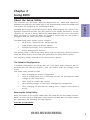
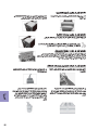
The manual consists of the following:
Describes features of the
motherboard.
H
page 1
Describes installation of
motherboard components.
H
page 45
H
page 7
H
page 37
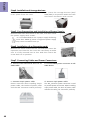
Quick Installation Guide
Introducing the Motherboard
Provides information on using
the BIOS Setup Utility.
Describes the motherboard
software.
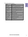
Limits and methods of mesurement of radio disturbance char-
acteristics of information technology equipment
EN 55022
EN 61000-3-2
Disturbances in supply systems caused
EN 61000-3-3
Disturbances in supply systems caused by household appli-
ances and similar electrical equipment “ Voltage fluctuations”
EN 55024
Information technology equipment-Immunity characteristics-
Limits and methods of measurement
EN 60950
Safety for information technology equipment including electri-
cal business equipment
CE marking
About the Manual
This device is in conformity with the following EC/EMC directives:
Chapter 3
Chapter 1
Multi-language
Chapter 2
Using BIOS
Using the Motherboard Software
Chapter 4
Trouble Shooting
Provides basic trouble
shooting tips.
page 41
H
Provides header pin definition
and jumper setting.
H
page 79
Appendix

iii
H16H2-MV USER MANUAL
TABLE OF CONTENTS
Preface i
Chapter 1 1
Introducing the Motherboard 1
Introduction...........................................................................................1
Pakage Contents..................................................................................1
Specifications......................................................................................2
Motherboard Components................................................................4
I/O Ports...............................................................................................6
Chapter 2 7
Using BIOS 7
About the Setup Utility.......................................................................7
The Standard Configuration.....................................................7
Entering the Setup Utility.........................................................7
Resetting the Default CMOS Values......................................8
Using BIOS...........................................................................................8
BIOS Navigation Keys...............................................................9
Main Menu.............................................................................10
Advanced Menu......................................................................11
Chipset Menu..........................................................................21
M.I.B III(MB Intelligent Bios III) Menu....................................28
Boot Menu...............................................................................32
Security Menu.........................................................................33
Save & Exit Menu....................................................................34
Updating the BIOS......................................................................35
Chapter 3 37
Using the Motherboard Software 57
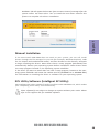
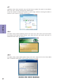
Auto-installing under Windows XP/7/8.......................................37
Running Setup........................................................................37
Manual Installation..........................................................................39
ECS Utility Software (Intelligent EZ Utility).....................................39

iv
H61H2-MV USER MANUAL
Chapter 4 41
Trouble Shooting 41
Start up problems during assembly..............................................41
Start up problems after prolong use............................................42
Maintenance and care tips..............................................................42
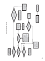
Basic Troubleshooting Flowchart.....................................................43
Multi-language Quick Installation Guide 45
English..............................................................................45
Brazilian Portuguese................................................................48
Hindi............................................................................................51
French......................................................................................54
Deutsch...............................................................................................57
Russian.........................................................................................60
Spanish...............................................................................................63
Indonesian...................................................................................66
Arabic...............................................................................................69
Simplified Chinese................................................................72
Korean...................................................................................................75
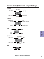
Appendix 79
Header Pin Definition and Jumper Setting 79

1
H61H2-MV USER MANUAL
Chapter 1
Chapter 1
Introducing the Motherboard
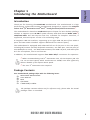
Introduction
Thank you for choosing the H61H2-MV motherboard. This motherboard is a high
performance, enhanced function motherboard designed to support the LGA1155
socket for 2
nd
/3
rd
Generation Intel
®®
®®
®
Core
TM
Family/Pentium/Celeron Processors*
1
.
This motherboard is based on Intel
®®
®®
®
H61 Express Chipset for best desktop platform
solution. It supports up to 16 GB of system memory with dual channel DDR3 1600
*
2
/
1333/1066 MHz. One PCI Express x16 slot, intended for Graphics Interface, is
supported, one PCI Express x1 slot is for extending usage.
It integrates USB 2.0 interface, supporting up to eight USB 2.0 ports (four USB 2.0
ports and two USB 2.0 headers support additional four USB 2.0 ports).
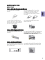
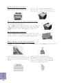
The motherboard is equipped with advanced full set of I/O ports in the rear panel,
including PS/2 mouse and PS/2 keyboard connectors, one VGA port, one DVI port (or
one HDMI port or none), one RJ45 LAN connector, four USB 2.0 ports, and audio jacks
6-ch for microphone, line-in and line-out.
In addition, this motherboard supports four SATA 3Gb/s connectors for expansion.
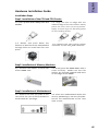
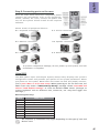
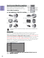
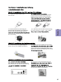
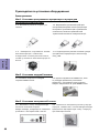
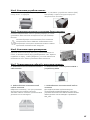
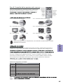
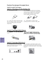
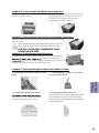
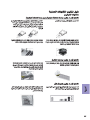
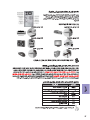
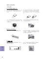
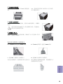
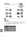
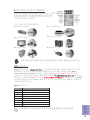
Your motherboard package ships with the following items:
Package Contents
H61H2-MV Motherboard
User Manual
DVD
I/O Shield
2 SATA 3Gb/s Cables
The package contents above are for reference only, please take the actual
package items as standard.
*
1
When accommodating Intel 3
rd
Generation CPU, the PCI Express 16X slot
can run at Gen3 speed, which accelerates on 32GB/s rate that effectively
delivers double of PCI Express Gen2 speed.
*
2
The Intel 3
rd
Generation CPU required.

Chapter 1
2
H61H2-MV USER MANUAL
CPU
Specifications
• Intel
®
H61 ChipsetChipset
• Dual-channel DDR3 memory architecture
• 2 x 240-pin DDR3 DIMM sockets support up to 16 GB
• Supports DDR3 1600
*/1333/1066 MHz DDR3 SDRAM
Memory
• 1 x PCI Express x16 Gen3 slot
• 1 x PCI Express x1 slot
• Supported by Intel
®
H61 Express Chipset
- 4 x Serial ATA 3Gb/s devices
Expansion
Slots
Storage
• 1 x PS/2 keyboard and PS/2 mouse connectors
• 1 x D-Sub port (VGA)
• 1 x DVI port(or HDMI port or none)
• 4 x USB 2.0 ports
• 1 x RJ45 LAN connector
• 1 x Audio port (1x Line in, 1x Line out, 1x Mic_in Rear)
Rear Panel I/O
• Realtek 8111E Gigabit Lan
- 10/100/1000 Fast Ethernet Controller
- Wake-on-LAN and remote wake-up support
• Realtek 8105
- 10/100 LAN Controller
- Wake-on-LAN and remote wake-up support
• LGA1155 socket for 2
nd
/3
rd
Generation Intel
®
Core
TM
Family/
Pentium/Celeron Processors
Note: Please go to ECS website for the latest CPU support list.
Note:
* The Intel 3
rd
Generation CPU required.
• 1 x 24-pin ATX Power Supply connector
• 1 x 4-pin 12V Power connector
• 1 x 4-pin CPU_FAN connector
• 1 x 3-pin SYS_FAN connector
• 2 x USB 2.0 headers support additional four USB 2.0 ports
• 4 x Serial SATA 3Gb/s connectors
• 1 x COM header
• 1 x Case open header
• 1 x Front panel USB power select jumper
• 1 x Rear USB/PS2 power select jumper
• 1 x Front Panel audio header
• 1 x Front Panel switch/LED header
• 1 x Speaker header
• 1 x ME_UNLOCK header
• 1 x CLR_CMOS header
Internal I/O
Connectors &
Headers
• Realtek ALC662
-
6 Channel High Definiton Audio Codec
- Compliant with HD audio specification
Audio
LAN

3
H61H2-MV USER MANUAL
Chapter 1
• AMI BIOS with 32Mb SPI Flash ROM
- Supports Plug and Play, STR(S3)/STD(S4)
- Supports Hardware Monitor
- Supports ACPI & DMI
- Supports Audio, LAN, can be disabled in BIOS
- Supports UEFI BIOS
- Supports Multi-language
- Supports Dual/Triple-Monitor function
- F7 hot key for boot up devices option
- Supports AC’97/HD Audio auto detect (default)
- Supports Pgup clear CMOS Hotkey (Has PS2 KB Model only)
System BIOS
Form Factor
• Micro-ATX Size, 195mm x 170mm
• Supports eBLU
• Supports eDLU
• Supports eSF
AP Suppport
Warning: Microsoft.NET Framework 3.5 is required.

Chapter 1
4
H61H2-MV USER MANUAL
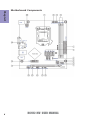
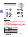
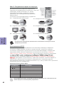
Motherboard Components

5
H61H2-MV USER MANUAL
Chapter 1
Table of Motherboard Components
LABEL COMPONENTS
1. CPU Socket LGA1155 socket
2. CPU_FAN 4-pin CPU cooling fan connector
3. SYS_FAN 3-pin system cooling fan connector
4. DDR3_1~2 240-pin DDR3 Module slots
5. ATX_POWER Standard 24-pin ATX power connector
6. SATA1~4 Serial ATA 3.0 Gb/s connectors
7. USBPWR_F1 Front panel USB power select jumper
8. F_USB1~2 Front panel USB 2.0 header s
9. SPK Speaker header
10. F_PANEL Front panel switch/LED header
11. COM Onboard serial port header
12. CLR_CMOS Clear CMOS jumper
13. CASE CASE open header
14. LPC_DEBUG LPC debug header-for factory use only
15. ME_UNLOCK ME unlock header-for factory use only
16. F_AUDIO Front panel audio header
17. PCIEX16 PCI Express slot for graphics interface
18. PCIE1 PCI Express x1 slot
19. USBPWR_R1 Rear USB/PS2 power select jumper
20. ATX12V 4-pin +12V power connector

Chapter 1
6
H61H2-MV USER MANUAL
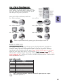
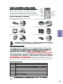
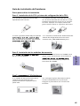
I/O Ports
1. PS/2 Mouse(green)
Use the upper PS/2 port to connect a PS/2 mouse.
2. PS/2 Keyboard(purple)
Use the lower PS/2 port to connect a PS/2 keyboard.
3. VGA Port
Connect your monitor to the VGA port.
4. USB 2.0 Ports
Use the USB 2.0 ports to connect USB 2.0 devices.
5. LAN Port
Connect an RJ-45 jack to the LAN port to connect your computer to the Network.
6. Line-in(blue)
It can be connected to an external CD/DVD player, Tape player or other audio
devices for audio input.
7. Line-out(lime)
It is used to connect to speakers or headphones.
8. Microphone(pink)
It is used to connect to a microphone.
LAN LED Status Description
OFF No data
Orange blinking Active
OFF No link
Green Link
Activity LED
Link LED
Link LED
LAN Port

H61H2-MV USER MANUAL
7
Chapter 2
About the Setup Utility
The computer uses the latest “American Megatrends Inc.” BIOS with support for
Windows Plug and Play. The CMOS chip on the motherboard contains the ROM setup
instructions for configuring the motherboard BIOS.
The BIOS (Basic Input and Output System) Setup Utility displays the system’s con-
figuration status and provides you with options to set system parameters. The pa-
rameters are stored in battery-backed-up CMOS RAM that saves this information
when the power is turned off. When the system is turned back on, the system is
configured with the values you stored in CMOS.
The BIOS Setup Utility enables you to configure:
• Hard drives, diskette drives and peripherals
• Video display type and display options
• Password protection from unauthorized use
• Power Management features
The settings made in the Setup Utility affect how the computer performs. Before
using the Setup Utility, ensure that you understand the Setup Utility options.
This chapter provides explanations for Setup Utility options.
The Standard Configuration
A standard configuration has already been set in the Setup Utility. However, we rec-
ommend that you read this chapter in case you need to make any changes in the
future.
This Setup Utility should be used:
• when changing the system configuration
• when a configuration error is detected and you are prompted to make
changes to the Setup Utility
• when trying to resolve IRQ conflicts
• when making changes to the Power Management configuration
• when changing the password or making other changes to the Security
Setup
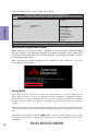
Press DEL to enter SETUP
Chapter 2
Using BIOS
Entering the Setup Utility
When you power on the system, BIOS enters the Power-On Self Test (POST) routines.
POST is a series of built-in diagnostics performed by the BIOS. After the POST routines
are completed, the following message appears:

H61H2-MV USER MANUAL
8
Chapter 2
Press the delete key to access BIOS Setup Utility.
Using BIOS
When you start the Setup Utility, the main menu appears. The main menu of the
Setup Utility displays a list of the options that are available. A highlight indicates
which option is currently selected. Use the cursor arrow keys to move the highlight
to other options. When an option is highlighted, execute the option by pressing
<Enter>.
Some options lead to pop-up dialog boxes that prompt you to verify that you wish to
execute that option. Other options lead to dialog boxes that prompt you for informa-
tion.
Some options (marked with a triangle
ff
ff
f) lead to submenus that enable you to change
the values for the option. Use the cursor arrow keys to scroll through the items in the
submenu.
Resetting the Default CMOS Values
When powering on for the first time, the POST screen may show a “CMOS Settings
Wrong” message. This standard message will appear following a clear CMOS data
at factory by the manufacturer. You simply need to Load Default Settings to reset
the default CMOS values.
Note: Changes to system hardware such as different CPU, memories, etc. may
also trigger this message.
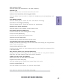
BIOS Information
System Language [English]
System Data [ Fri 09/14/2012]
System Time [00:00:31]
Choose the system default
language.
Aptio Setup Utility - Copyright (C) 2012 American Megatrends, Inc.
Version 2.14.1219. Copyright (C) 2012, American Megatrends, Inc.
Main Advanced Chipset M.I.B III Boot Security Save & Exit
F2:Previous Values
F1:General Help
+/- : Change Opt.
Enter : Select
lk
mn
:Select Screen
:Select Item
F3:Optimized Defaults
F4:Save & Exit
ESC:Exit

H61H2-MV USER MANUAL
9
Chapter 2
The default BIOS setting for this motherboard apply for most conditions
with optimum performance. We do not suggest users change the default
values in the BIOS setup and take no responsibility to any damage caused
by changing the BIOS settings.
In this manual, default values are enclosed in parenthesis. Submenu items are
denoted by a triangle
ff
ff
f .
BIOS Navigation Keys
The BIOS navigation keys are listed below:
KEY FUNCTION
Scrolls through the items on a menu
+/-Change Opt.
F2 Previous Value
F3 Optimized Defaults
F1 General Help
ESC Exits the current menu
mnlk
Enter Select
F4 Save & Exit
For the purpose of better product maintenance, the manufacture reserves
the right to change the BIOS items presented in this manual. The BIOS setup
screens shown in this chapter are for reference only and may differ from
the actual BIOS. Please visit the manufacture’s website for updated
manual.

H61H2-MV USER MANUAL
10
Chapter 2
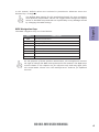
Date & Time
The Date and Time items show the current date and time on the computer. If you are
running a Windows OS, these items are automatically updated whenever you make
changes to the Windows Date and Time Properties utility.
System Language (English)
This item is used to set system language.
When you enter the BIOS Setup program, the main menu appears, giving you an
overview of the basic system information. Select an item and press <Enter> to
display the submenu.
Main Menu
BIOS Information
System Language [English]
System Data [ Fri 09/14/2012]
System Time [00:00:31]
Choose the system default
language.
Aptio Setup Utility - Copyright (C) 2012 American Megatrends, Inc.
Version 2.14.1219. Copyright (C) 2012, American Megatrends, Inc.
Main Advanced Chipset M.I.B III Boot Security Save & Exit
F2:Previous Values
F1:General Help
+/- : Change Opt.
Enter : Select
lk
mn
:Select Screen
:Select Item
F3:Optimized Defaults
F4:Save & Exit
ESC:Exit

H61H2-MV USER MANUAL
11
Chapter 2
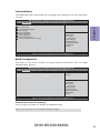
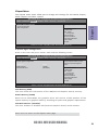
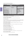
The Advanced menu items allow you to change the settings for the CPU and other
system.
Advanced Menu
Onboard LAN Controller (Enabled)
Use this item to enable or disable the Onboard LAN.
Press <Esc> to return to the Advanced Menu page.
ff
ff
f
LAN Configuration
The item in the menu shows the LAN-related information that the BIOS
automatically detects.
Enabled/Disabled Onboard LAN 1
Controller
LAN Configuration
Onboard LAN Controller [Enabled]
Aptio Setup Utility - Copyright (C) 2012 American Megatrends, Inc.
Version 2.14.1219. Copyright (C) 2012, American Megatrends, Inc.
Main Advanced Chipset M.I.B III Boot Security Save & Exit
LAN Configuration
PC Health Status
Power Management Setup
ACPI Settings
CPU Configuration
SATA Configuration
USB Configuration
Super IO Configuration
Intel (R) Smart Connect Technology
LAN Configuration Parameters
Aptio Setup Utility - Copyright (C) 2012 American Megatrends, Inc.
Version 2.14.1219. Copyright (C) 2012, American Megatrends, Inc.
ff
ff
f
ff
ff
f
ff
ff
f
ff
ff
f
ff
ff
f
ff
ff
f
ff
ff
f
ff
ff
f
Main Advanced Chipset M.I.B III Boot Security Save & Exit
F2:Previous Values
F1:General Help
+/- : Change Opt.
Enter : Select
lk
mn
:Select Screen
:Select Item
F3:Optimized Defaults
F4:Save & Exit
ESC:Exit
F2:Previous Values
F1:General Help
+/- : Change Opt.
Enter : Select
lk
mn
:Select Screen
:Select Item
F3:Optimized Defaults
F4:Save & Exit
ESC:Exit
ff
ff
f

H61H2-MV USER MANUAL
12
Chapter 2
ff
ff
f
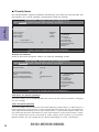
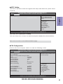
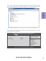
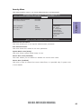
PC Health Status
On motherboards support hardware monitoring, this item lets you monitor the
parameters for critical voltages, temperatures and fan speeds.
Main Advanced Chipset M.I.B III Boot Security Save & Exit
Version 2.14.1219. Copyright (C) 2012, American Megatrends,
Inc.
Aptio Setup Utility - Copyright (C) 2012 American Megatrends, Inc.
Aptio Setup Utility - Copyright (C) 2012 American Megatrends, Inc.
Version 2.14.1219. Copyright (C) 2012, American Megatrends, Inc.
Main
Advanced Chipset M.I.B III Boot Security Save & Exit
Scroll to this item and press <Enter> to view the following screen:
fSmart Fan Function
CPU Smart Fan Control (Enabled)
This item allows you to enable/disable the control of the CPU fan speed by changing
the fan voltage.
Smart Fan Mode (Normal)
This item allows you to select the fan mode (Normal, Quiet, Silent, or Manual) for a
better operation environment. If you choose Normal mode, the fan speed will be
auto adjusted depending on the CPU temperature. If you choose Quiet mode, the
fan speed will be auto minimized for quiet environment. If you choose Silent mode,
the fan speed will be auto restricted to make system more quietly. If you choose
Manual mode, the fan speed will be adjust depending on users’ parameters.
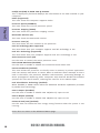
CPU Fan Speed : 2824RPM
CPU Voltage : 1.056V
DIMM Voltage : 1.548V
AXG Voltage : 0.012V
-=- PECI Mode -=-
Offset to TCC Activation Temp. : -53
Smart Fan Function
f
PC Health Status
CPU Smart Fan Control [Enabled]
Smart Fan Mode [Normal]
Smart Fan start PWM value 180
Smart Fan start PWM TEMP(-) 30
Delta T 3
Smart Fan Slope PWM value 10 PWM value/unit
CPU Fan Full Speed Offset (-) 23
F2:Previous Values
F1:General Help
+/- : Change Opt.
Enter : Select
lk
mn
:Select Screen
:Select Item
F3:Optimized Defaults
F4:Save & Exit
ESC:Exit
F2:Previous Values
F1:General Help
+/- : Change Opt.
Enter : Select
lk
mn
:Select Screen
:Select Item
F3:Optimized Defaults
F4:Save & Exit
ESC:Exit

H61H2-MV USER MANUAL
13
Chapter 2
• CPU Fan Speed
• CPU Voltage
• DIMM Voltage
• AXG Voltage
System Component Characteristics
These items display the monitoring of the overall inboard hardware health
events, such as CPU fan speed, CPU & DIMM voltage... etc.
Press <Esc> to return to the Advanced Menu page.
Press <Esc> to return to the PC Health Status page.
Smart Fan Start PWM value (180)
This item is used to set the start PWM value of the smart fan.
Smart Fan Start TEMP(-) (30)
This item is used to set the start temperature of the smart fan.
DeltaT (3)
This item specifies the range that controls CPU temperature and keeps it from going
so high or so low when smart fan works.
SMART Fan Slope PWM value (10 PWM value/unite)
This item is used to set the Slope Select PWM of the smart fan.
CPU Fan Full Speed Offset(-) (23)
This item is used to set the CPU fan full speed offset value.

H61H2-MV USER MANUAL
14
Chapter 2
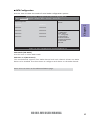
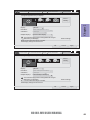
EUP Function (Enabled)
This item allows user to enable or disable EUP function.
Resume By PS2 MS (S3) (Disabled)
This item enables or disables you to allow mouse activity to awaken the system
from power saving mode.
ff
ff
f
Power Management Setup
This page sets up some parameters for system power management operation.
Resume By PME (Disabled)
The system can be turned off with a software command. If you enable this item, the
system can automatically resume if there is an incoming call on the PCI Modem or
PCI LAN card. You must use an ATX power supply in order to use this feature. Use this
item to do wake-up action if inserting the PCI card.
Resume By USB 1.x/2.0(S3) (Disabled)
This item allows you to enable/disable the USB device wakeup function from S3
mode.
Resume By RING (Disabled)
The system can be turned off with a software command. If you enable this item, the
system can automatically resume if there is an incoming call on the Modem. You
must use an ATX power supply in order to use this feature.
Resume By PS2 KB (S3) (Disabled)
This item enables or disables you to allow keyboard activity to awaken the system
from power saving mode.
Power Management Setup
Resume By RING Disabled]
Resume By PME [Disabled]
Resume By USB 1.x/2.0 (S3) [Disabled]
Resume By PS2 KB (S3) [Disabled]
Resume By PS2 MS (S3) [Disabled]
EUP Function [Enabled]
Power LED Type [Dual Color LED]
Aptio Setup Utility - Copyright (C) 2012 American Megatrends, Inc.
Main
Advanced Chipset M.I.B III Boot Security Save & Exit
Version 2.14.1219. Copyright (C) 2012, American Megatrends, Inc.
About Resume by Ring
Power LED Type (Dual Color LED)
This item shows the type of the power LED.
Press <Esc> to return to the Advanced Menu page.
F2:Previous Values
F1:General Help
+/- : Change Opt.
Enter : Select
lk
mn
:Select Screen
:Select Item
F3:Optimized Defaults
F4:Save & Exit
ESC:Exit

H61H2-MV USER MANUAL
15
Chapter 2
ff
ff
f
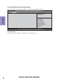
ACPI Setting
The item in the menu shows the highest ACPI sleep state when the system enters
suspend.
ACPI Sleep State (S3(Suspend to RAM))
This item allows user to enter the ACPI S3 (Suspend toRAM) Sleep State (default).
Press <Esc> to return to the Advanced Menu page.
ff
ff
f
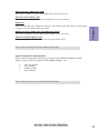
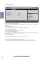
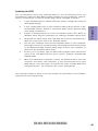
CPU Configuration
Scroll to this item and press <Enter> to view the following screen:
CPU Configuration
Intel(R) Core(TM) i5-3450K CPU @ 3.10GHz
64-bit Supported
Processor Speed 3100 MHz
Processor Stepping 306a8
Microcode Revision 10
Processor Cores 4
Intel HT Technology Not Supported
Intel VT-x Technology Supported
Active Processor Cores [All]
Limit CPUID Maximum [Disabled]
Execute Disable Bit [Enabled]
Intel Virtualization Technology [Enabled]
CPU C3 Report [Disabled]
CPU C6 Report [Enabled]
Enhanced Halt (C1E) [Enabled]
Aptio Setup Utility - Copyright (C) 2012 American Megatrends, Inc.
Version 2.14.1219. Copyright (C) 2012, American Megatrends, Inc.
Number of cores to enable in each
processor package.
Main Advanced Chipset M.I.B III Boot Security Save & Exit
ACPI Settings
ACPI Sleep State [S3 (Suspend to RAM)]
Aptio Setup Utility - Copyright (C) 2012 American Megatrends, Inc.
Version 2.14.1219. Copyright (C) 2012, American Megatrends, Inc.
Select the highest ACPI sleep
state the system will enter
when the SUSPEND button is
pressed.
Main Advanced Chipset M.I.B III Boot Security Save & Exit
F2:Previous Values
F1:General Help
+/- : Change Opt.
Enter : Select
lk
mn
:Select Screen
:Select Item
F3:Optimized Defaults
F4:Save & Exit
ESC:Exit
F2:Previous Values
F1:General Help
+/- : Change Opt.
Enter : Select
lk
mn
:Select Screen
:Select Item
F3:Optimized Defaults
F4:Save & Exit
ESC:Exit

H61H2-MV USER MANUAL
16
Chapter 2
Intel(R) Core(TM) i5-3450K CPU @ 3.10GHz
This is display-only field and diaplays the information of the CPU installed in your
computer.
64-bit (Supported)
This item shows the computer supports 64-bit.
Processor Speed (3100MHz)
This item shows the current processor speed.
Processor Stepping (306a8)
This item shows the processor stepping version.
Microcode Revision (10)
This item shows the Microcode version.
Processor Cores (4)
This item shows the core number of the processor.
Execute Disable Bit (Enabled)
This item allows the processor to classify areas in memory by where application
code can execute and where it cannot. When a malicious worm attempts to insert
code in the buffer, the processor disables code execution, preventing damage or
worm propagation. Replacing older computers with Execute Disable Bit enabled
systems can halt worm attacks, reducing the need for virus related repair.
Intel Virtualization Technology (Enabled)
When disabled, a VMM cannot utilize the additional hardware capabilities provided
by Vandor Pool Technology.
Enhanced Halt (C1E) (Enabled)
Use this item to enable the CPU energy-saving function when the system is not
running.
Press <Esc> to return to the Advanced Menu page.
Limit CPUID Maximum (Disabled)
Use this item to enable or disable the maximum CPUID value limit.
Intel HT Technology (Not Supported)
This item shows that your computer supports Intel HT technology or not.
Intel VT-x Technology (Supported)
This item shows that your computer supports Intel VT-x technology or not.
CPU C3 Report (Disabled)
Use this item to enable or disable CPU C3(ACPI C2) report to OS.
CPU C6 Report (Enabled)
Use this item to enable or disable CPU C6(ACPI C3) report to OS.
Active Processor Cores (All)
Use this item to control the active processor cores.
Page is loading ...
Page is loading ...
Page is loading ...
Page is loading ...
Page is loading ...
Page is loading ...
Page is loading ...
Page is loading ...
Page is loading ...
Page is loading ...
Page is loading ...
Page is loading ...
Page is loading ...
Page is loading ...
Page is loading ...
Page is loading ...
Page is loading ...
Page is loading ...
Page is loading ...
Page is loading ...
Page is loading ...
Page is loading ...
Page is loading ...
Page is loading ...
Page is loading ...
Page is loading ...
Page is loading ...
Page is loading ...
Page is loading ...
Page is loading ...
Page is loading ...
Page is loading ...
Page is loading ...
Page is loading ...
Page is loading ...
Page is loading ...
Page is loading ...
Page is loading ...
Page is loading ...
Page is loading ...
Page is loading ...
Page is loading ...
Page is loading ...
Page is loading ...
Page is loading ...
Page is loading ...
Page is loading ...
Page is loading ...
Page is loading ...
Page is loading ...
Page is loading ...
Page is loading ...
Page is loading ...
Page is loading ...
Page is loading ...
Page is loading ...
Page is loading ...
Page is loading ...
Page is loading ...
Page is loading ...
Page is loading ...
Page is loading ...
Page is loading ...
Page is loading ...
-
 1
1
-
 2
2
-
 3
3
-
 4
4
-
 5
5
-
 6
6
-
 7
7
-
 8
8
-
 9
9
-
 10
10
-
 11
11
-
 12
12
-
 13
13
-
 14
14
-
 15
15
-
 16
16
-
 17
17
-
 18
18
-
 19
19
-
 20
20
-
 21
21
-
 22
22
-
 23
23
-
 24
24
-
 25
25
-
 26
26
-
 27
27
-
 28
28
-
 29
29
-
 30
30
-
 31
31
-
 32
32
-
 33
33
-
 34
34
-
 35
35
-
 36
36
-
 37
37
-
 38
38
-
 39
39
-
 40
40
-
 41
41
-
 42
42
-
 43
43
-
 44
44
-
 45
45
-
 46
46
-
 47
47
-
 48
48
-
 49
49
-
 50
50
-
 51
51
-
 52
52
-
 53
53
-
 54
54
-
 55
55
-
 56
56
-
 57
57
-
 58
58
-
 59
59
-
 60
60
-
 61
61
-
 62
62
-
 63
63
-
 64
64
-
 65
65
-
 66
66
-
 67
67
-
 68
68
-
 69
69
-
 70
70
-
 71
71
-
 72
72
-
 73
73
-
 74
74
-
 75
75
-
 76
76
-
 77
77
-
 78
78
-
 79
79
-
 80
80
-
 81
81
-
 82
82
-
 83
83
-
 84
84


American Megatrends H61H2-MV (V1.0) User manual
- Category
- Motherboards
- Type
- User manual
- This manual is also suitable for
Ask a question and I''ll find the answer in the document
Finding information in a document is now easier with AI