System Password
Option Settings
You cannot change or enter a new system password if either of the following two options is displayed:
l Set — A system password is assigned.
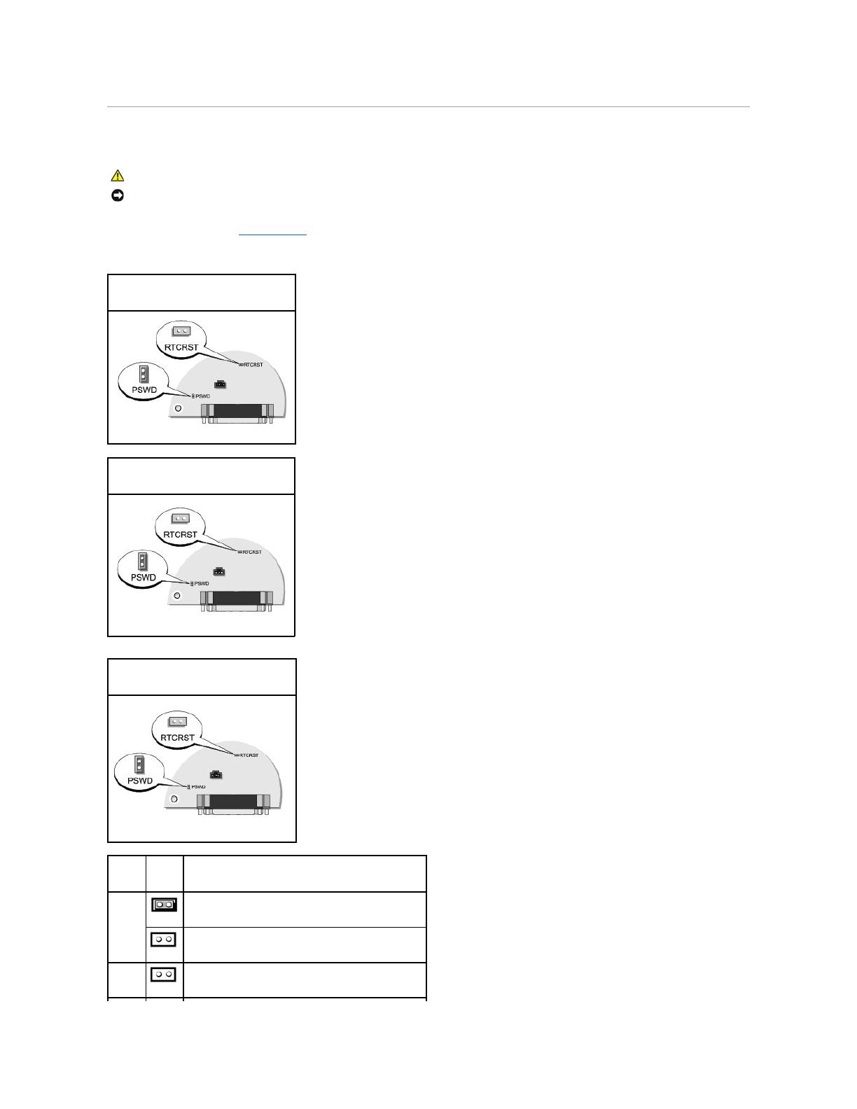
l Disabled — The system password is disabled by a jumper setting on the system board.
You can only assign a system password when the following option is displayed:
l Not Set — No system password is assigned and the password jumper on the system board is in the enabled position (the default setting).
Assigning a System Password
To escape from the field without assigning a system password, press <Tab> or the <Shift><Tab> key combination to move to another field, or press <Esc> at
any time before you complete step 5.
1. Enter system setup and verify that Password Status is set to Unlocked.
2. Highlight System Password, and then press the left- or right-arrow key.
The option heading changes to Enter Password, followed by an empty 32-character field in square brackets.
3. Type your new system password.
You can use up to 32 characters. To erase a character when entering your password, press <Backspace> or the left-arrow key. The password is not
case sensitive.
Certain key combinations are not valid. If you enter one of these combinations, the speaker emits a beep.
As you press each character key (or the spacebar for a blank space), a placeholder appears in the field.
4. Press <Enter>.
If the new system password is less than 32 characters, the whole field fills with placeholders. Then the option heading changes to Verify Password,
followed by another empty 32-character field in square brackets.
5. To confirm your password, type it a second time and press <Enter>.
The password setting changes to Set.
6. Exit system setup.
Password protection takes effect when you restart the computer.
Typing Your System Password
When you start or restart your computer, the following prompt appears on the screen.
If Password Status is set to Locked:
Type the password and press <Enter>.
If you have assigned an administrator password, the computer accepts your administrator password as an alternate system password.
If you type a wrong or incomplete system password, the following message appears on the screen:
** Incorrect password. **
If you again type an incorrect or incomplete system password, the same message appears on the screen. The third and subsequent times you type an
incorrect or incomplete system password, the computer displays the following message:
** Incorrect password. **
Number of unsuccessful password attempts: 3
System halted! Must power down.
Even after your computer is turned off and on, the previous message is displayed each time you type an incorrect or incomplete system password.