HP STORAGEWORKS A7540-96010 User manual
- Category
- Network switches
- Type
- User manual
This manual is also suitable for

Installation Guide
HP StorageWorks
2/8q Fibre Channel Switch
First Edition (November 2004)
Part Number: A7540-96010
This manual describes the features of, and installation procedures for, the HP StorageWorks 2/8q Fibre
Channel Switch.
Sections include:
■ Introduction—provides an overview of LEDs, connections, and user controls.
■ Planning—describes the factors to consider when planning a fabric.
■ Installing—explains how to install and configure the switch.
■ Troubleshooting—describes the diagnostic methods and troubleshooting procedures.
■ Regulatory Compliance Notices—includes notices about the switch.
■ Electrostatic Discharge—discusses static electricity concerns.
■ Specifications —ists the switch specifications.

© Copyright 2004 Hewlett-Packard Development Company, L.P.
Hewlett-Packard Company makes no warranty of any kind with regard to this material, including, but not limited to, the implied
warranties of merchantability and fitness for a particular purpose. Hewlett-Packard shall not be liable for errors contained herein or for
incidental or consequential damages in connection with the furnishing, performance, or use of this material.
This document contains proprietary information, which is protected by copyright. No part of this document may be photocopied,
reproduced, or translated into another language without the prior written consent of Hewlett-Packard. The information contained in this
document is subject to change without notice. The only warranties for HP products and services are set forth in the express warranty
statements accompanying such products and services. Nothing herein should be construed as constituting an additional warranty. HP
shall not be liable for technical or editorial errors or omissions contained herein.
Microsoft® and Windows® are U.S. registered trademarks of Microsoft Corporation.
Linux® is a U.S. registered trademard of Linus Torvalds.
Hewlett-Packard Company shall not be liable for technical or editorial errors or omissions contained herein. The information is provided
“as is” without warranty of any kind and is subject to change without notice. The warranties for Hewlett-Packard Company products are
set forth in the express limited warranty statements for such products. Nothing herein should be construed as constituting an additional
warranty.
HP StorageWorks 2/8q Fibre Channel Switch Installation Guide
First Edition (November 2004)
Part Number: A7540-96010

3HP StorageWorks 2/8q Fibre Channel Switch Installation Guide
Contents
Contents
About this Guide. . . . . . . . . . . . . . . . . . . . . . . . . . . . . . . . . . . . . . . . . . . . . . . . . . . . . . . . . . . . . . . 7
Intended audience. . . . . . . . . . . . . . . . . . . . . . . . . . . . . . . . . . . . . . . . . . . . . . . . . . . . . . . . . . . . . . . . . . . . . . . . .7
Related documentation . . . . . . . . . . . . . . . . . . . . . . . . . . . . . . . . . . . . . . . . . . . . . . . . . . . . . . . . . . . . . . . . . . . . .7
Document conventions . . . . . . . . . . . . . . . . . . . . . . . . . . . . . . . . . . . . . . . . . . . . . . . . . . . . . . . . . . . . . . . . . . . . .8
Text symbols. . . . . . . . . . . . . . . . . . . . . . . . . . . . . . . . . . . . . . . . . . . . . . . . . . . . . . . . . . . . . . . . . . . . . . . . . . . . .8
Equipment symbols . . . . . . . . . . . . . . . . . . . . . . . . . . . . . . . . . . . . . . . . . . . . . . . . . . . . . . . . . . . . . . . . . . . . . . .9
Rack stability . . . . . . . . . . . . . . . . . . . . . . . . . . . . . . . . . . . . . . . . . . . . . . . . . . . . . . . . . . . . . . . . . . . . . . . . . . .10
Getting help . . . . . . . . . . . . . . . . . . . . . . . . . . . . . . . . . . . . . . . . . . . . . . . . . . . . . . . . . . . . . . . . . . . . . . . . . . . .10
HP installation and configuration assistance . . . . . . . . . . . . . . . . . . . . . . . . . . . . . . . . . . . . . . . . . . . . . . . .10
HP technical support . . . . . . . . . . . . . . . . . . . . . . . . . . . . . . . . . . . . . . . . . . . . . . . . . . . . . . . . . . . . . . . . . .11
HP storage web site . . . . . . . . . . . . . . . . . . . . . . . . . . . . . . . . . . . . . . . . . . . . . . . . . . . . . . . . . . . . . . . . . . .11
HP authorized reseller . . . . . . . . . . . . . . . . . . . . . . . . . . . . . . . . . . . . . . . . . . . . . . . . . . . . . . . . . . . . . . . . .11
1 Introduction . . . . . . . . . . . . . . . . . . . . . . . . . . . . . . . . . . . . . . . . . . . . . . . . . . . . . . . . . . . . . . . . . 13
Switch chassis features . . . . . . . . . . . . . . . . . . . . . . . . . . . . . . . . . . . . . . . . . . . . . . . . . . . . . . . . . . . . . . . . . . . .13
Power supply . . . . . . . . . . . . . . . . . . . . . . . . . . . . . . . . . . . . . . . . . . . . . . . . . . . . . . . . . . . . . . . . . . . . . . . .14
Serial port. . . . . . . . . . . . . . . . . . . . . . . . . . . . . . . . . . . . . . . . . . . . . . . . . . . . . . . . . . . . . . . . . . . . . . . . . . .14
Chassis LEDs . . . . . . . . . . . . . . . . . . . . . . . . . . . . . . . . . . . . . . . . . . . . . . . . . . . . . . . . . . . . . . . . . . . . . . . .14
Input Power LED (green) . . . . . . . . . . . . . . . . . . . . . . . . . . . . . . . . . . . . . . . . . . . . . . . . . . . . . . . . . . .14
Heartbeat LED (green) . . . . . . . . . . . . . . . . . . . . . . . . . . . . . . . . . . . . . . . . . . . . . . . . . . . . . . . . . . . . .15
System Fault LED (solid amber). . . . . . . . . . . . . . . . . . . . . . . . . . . . . . . . . . . . . . . . . . . . . . . . . . . . . .15
Ethernet port. . . . . . . . . . . . . . . . . . . . . . . . . . . . . . . . . . . . . . . . . . . . . . . . . . . . . . . . . . . . . . . . . . . . . . . . .15
Maintenance button . . . . . . . . . . . . . . . . . . . . . . . . . . . . . . . . . . . . . . . . . . . . . . . . . . . . . . . . . . . . . . . . . . .16
Resetting the switch. . . . . . . . . . . . . . . . . . . . . . . . . . . . . . . . . . . . . . . . . . . . . . . . . . . . . . . . . . . . . . . .16
Placing the switch in maintenance mode. . . . . . . . . . . . . . . . . . . . . . . . . . . . . . . . . . . . . . . . . . . . . . . .16
Exiting maintenance mode . . . . . . . . . . . . . . . . . . . . . . . . . . . . . . . . . . . . . . . . . . . . . . . . . . . . . . . . . .16
Fibre Channel ports and LEDs. . . . . . . . . . . . . . . . . . . . . . . . . . . . . . . . . . . . . . . . . . . . . . . . . . . . . . . . . . .17
Port Logged-in LED (green) . . . . . . . . . . . . . . . . . . . . . . . . . . . . . . . . . . . . . . . . . . . . . . . . . . . . . . . . .17
Port Activity LED (green) . . . . . . . . . . . . . . . . . . . . . . . . . . . . . . . . . . . . . . . . . . . . . . . . . . . . . . . . . . .17
SFP transceivers. . . . . . . . . . . . . . . . . . . . . . . . . . . . . . . . . . . . . . . . . . . . . . . . . . . . . . . . . . . . . . . . . . . . . .18
Port types . . . . . . . . . . . . . . . . . . . . . . . . . . . . . . . . . . . . . . . . . . . . . . . . . . . . . . . . . . . . . . . . . . . . . . . . . . .18
Switch management . . . . . . . . . . . . . . . . . . . . . . . . . . . . . . . . . . . . . . . . . . . . . . . . . . . . . . . . . . . . . . . . . . . . . .19
Switch Manager user interface. . . . . . . . . . . . . . . . . . . . . . . . . . . . . . . . . . . . . . . . . . . . . . . . . . . . . . . . . . .19
Command Line Interface . . . . . . . . . . . . . . . . . . . . . . . . . . . . . . . . . . . . . . . . . . . . . . . . . . . . . . . . . . . . . . .19
File Transfer Protocol . . . . . . . . . . . . . . . . . . . . . . . . . . . . . . . . . . . . . . . . . . . . . . . . . . . . . . . . . . . . . . . . .19
Simple Network Management Protocol. . . . . . . . . . . . . . . . . . . . . . . . . . . . . . . . . . . . . . . . . . . . . . . . . . . .19

Contents
4 HP StorageWorks 2/8q Fibre Channel Switch Installation Guide
2 Planning. . . . . . . . . . . . . . . . . . . . . . . . . . . . . . . . . . . . . . . . . . . . . . . . . . . . . . . . . . . . . . . . . . . . 21
Devices . . . . . . . . . . . . . . . . . . . . . . . . . . . . . . . . . . . . . . . . . . . . . . . . . . . . . . . . . . . . . . . . . . . . . . . . . . . . . . . .22
Device access . . . . . . . . . . . . . . . . . . . . . . . . . . . . . . . . . . . . . . . . . . . . . . . . . . . . . . . . . . . . . . . . . . . . . . . . . . .22
Hard zones (Access Control Lists). . . . . . . . . . . . . . . . . . . . . . . . . . . . . . . . . . . . . . . . . . . . . . . . . . . . . . . .23
Soft zones. . . . . . . . . . . . . . . . . . . . . . . . . . . . . . . . . . . . . . . . . . . . . . . . . . . . . . . . . . . . . . . . . . . . . . . . . . .23
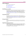
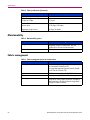
Performance . . . . . . . . . . . . . . . . . . . . . . . . . . . . . . . . . . . . . . . . . . . . . . . . . . . . . . . . . . . . . . . . . . . . . . . . . . . .24
Distance . . . . . . . . . . . . . . . . . . . . . . . . . . . . . . . . . . . . . . . . . . . . . . . . . . . . . . . . . . . . . . . . . . . . . . . . . . . .24
Bandwidth . . . . . . . . . . . . . . . . . . . . . . . . . . . . . . . . . . . . . . . . . . . . . . . . . . . . . . . . . . . . . . . . . . . . . . . . . .24
Latency. . . . . . . . . . . . . . . . . . . . . . . . . . . . . . . . . . . . . . . . . . . . . . . . . . . . . . . . . . . . . . . . . . . . . . . . . . . . .24
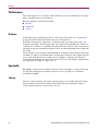
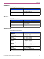
Fabric security . . . . . . . . . . . . . . . . . . . . . . . . . . . . . . . . . . . . . . . . . . . . . . . . . . . . . . . . . . . . . . . . . . . . . . . . . .25
User account security. . . . . . . . . . . . . . . . . . . . . . . . . . . . . . . . . . . . . . . . . . . . . . . . . . . . . . . . . . . . . . . . . .25
Simple Network Management Protocol security . . . . . . . . . . . . . . . . . . . . . . . . . . . . . . . . . . . . . . . . . . . . .25
Fabric management. . . . . . . . . . . . . . . . . . . . . . . . . . . . . . . . . . . . . . . . . . . . . . . . . . . . . . . . . . . . . . . . . . . . . . .25
3 Installing . . . . . . . . . . . . . . . . . . . . . . . . . . . . . . . . . . . . . . . . . . . . . . . . . . . . . . . . . . . . . . . . . . . 27
Site requirements . . . . . . . . . . . . . . . . . . . . . . . . . . . . . . . . . . . . . . . . . . . . . . . . . . . . . . . . . . . . . . . . . . . . . . . .27
Installing and initially configuring the switch . . . . . . . . . . . . . . . . . . . . . . . . . . . . . . . . . . . . . . . . . . . . . . . . . .28
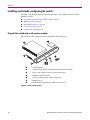
Unpack the switch and verify carton contents . . . . . . . . . . . . . . . . . . . . . . . . . . . . . . . . . . . . . . . . . . . . . . .28
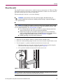
Mount the switch . . . . . . . . . . . . . . . . . . . . . . . . . . . . . . . . . . . . . . . . . . . . . . . . . . . . . . . . . . . . . . . . . . . . .29
Install SFP transceivers . . . . . . . . . . . . . . . . . . . . . . . . . . . . . . . . . . . . . . . . . . . . . . . . . . . . . . . . . . . . . . . .34
Connect the cables . . . . . . . . . . . . . . . . . . . . . . . . . . . . . . . . . . . . . . . . . . . . . . . . . . . . . . . . . . . . . . . . . . . .35
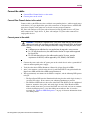
Connect Fibre Channel devices to the switch . . . . . . . . . . . . . . . . . . . . . . . . . . . . . . . . . . . . . . . . . . . .35
Connect power to the switch . . . . . . . . . . . . . . . . . . . . . . . . . . . . . . . . . . . . . . . . . . . . . . . . . . . . . . . . .35
Configure the switch . . . . . . . . . . . . . . . . . . . . . . . . . . . . . . . . . . . . . . . . . . . . . . . . . . . . . . . . . . . . . . . . . .36
Installing Switch Manager on Windows® systems. . . . . . . . . . . . . . . . . . . . . . . . . . . . . . . . . . . . . . . .36
Installing Switch Manager on Linux® systems . . . . . . . . . . . . . . . . . . . . . . . . . . . . . . . . . . . . . . . . . .36
Backing up the switch configuration . . . . . . . . . . . . . . . . . . . . . . . . . . . . . . . . . . . . . . . . . . . . . . . . . . . . . . . . .37
Powering down the switch . . . . . . . . . . . . . . . . . . . . . . . . . . . . . . . . . . . . . . . . . . . . . . . . . . . . . . . . . . . . . . . . .37
Updating switch firmware . . . . . . . . . . . . . . . . . . . . . . . . . . . . . . . . . . . . . . . . . . . . . . . . . . . . . . . . . . . . . . . . .38
Using Switch Manager to install firmware . . . . . . . . . . . . . . . . . . . . . . . . . . . . . . . . . . . . . . . . . . . . . . . . .38
Using the CLI to install firmware . . . . . . . . . . . . . . . . . . . . . . . . . . . . . . . . . . . . . . . . . . . . . . . . . . . . . . . .38
4 Troubleshooting . . . . . . . . . . . . . . . . . . . . . . . . . . . . . . . . . . . . . . . . . . . . . . . . . . . . . . . . . . . . . . 41
POST diagnostics . . . . . . . . . . . . . . . . . . . . . . . . . . . . . . . . . . . . . . . . . . . . . . . . . . . . . . . . . . . . . . . . . . . . . . . .42
Heartbeat LED blink patterns. . . . . . . . . . . . . . . . . . . . . . . . . . . . . . . . . . . . . . . . . . . . . . . . . . . . . . . . . . . .42
Internal firmware failure blink pattern . . . . . . . . . . . . . . . . . . . . . . . . . . . . . . . . . . . . . . . . . . . . . . . . .43
System error blink pattern . . . . . . . . . . . . . . . . . . . . . . . . . . . . . . . . . . . . . . . . . . . . . . . . . . . . . . . . . . .43
Configuration file system error blink pattern . . . . . . . . . . . . . . . . . . . . . . . . . . . . . . . . . . . . . . . . . . . .43
Over temperature blink pattern . . . . . . . . . . . . . . . . . . . . . . . . . . . . . . . . . . . . . . . . . . . . . . . . . . . . . . .44
Logged-In LED indications . . . . . . . . . . . . . . . . . . . . . . . . . . . . . . . . . . . . . . . . . . . . . . . . . . . . . . . . . . . . .44
Port Error blinking pattern. . . . . . . . . . . . . . . . . . . . . . . . . . . . . . . . . . . . . . . . . . . . . . . . . . . . . . . . . . .45
Chassis diagnostics . . . . . . . . . . . . . . . . . . . . . . . . . . . . . . . . . . . . . . . . . . . . . . . . . . . . . . . . . . . . . . . . . . . . . . .46
Input Power LED is extinguished . . . . . . . . . . . . . . . . . . . . . . . . . . . . . . . . . . . . . . . . . . . . . . . . . . . . . . . .46
System Fault LED is illuminated. . . . . . . . . . . . . . . . . . . . . . . . . . . . . . . . . . . . . . . . . . . . . . . . . . . . . . . . .46
Maintenance mode options. . . . . . . . . . . . . . . . . . . . . . . . . . . . . . . . . . . . . . . . . . . . . . . . . . . . . . . . . . . . . . . . .47
Maintenance menu – Exit . . . . . . . . . . . . . . . . . . . . . . . . 48
Maintenance menu – Image Unpack . . . . . . . . . . . . . . . . . . . . 48
Maintenance menu – Reset Network Config . . . . . . . . . . . . . . . . 48
Maintenance menu – Reset User Accounts to Default . . . . . . . . . . . 48
Maintenance menu – Copy Log Files . . . . . . . . . . . . . . . . . . . 48

Contents
5HP StorageWorks 2/8q Fibre Channel Switch Installation Guide
Maintenance menu – Remove Switch Config . . . . . . . . . . . . . . . . 48
Maintenance menu – Remake Filesystem . . . . . . . . . . . . . . . . . . 49
Maintenance menu – Reset Switch . . . . . . . . . . . . . . . . . . . . 49
Maintenance menu – Show Firmware Versions . . . . . . . . . . . . . . . 49
Maintenance menu – Set Active Image . . . . . . . . . . . . . . . . . . 49
Maintenance menu – Update Boot Loader . . . . . . . . . . . . . . . . . 49
A Regulatory Compliance Notices . . . . . . . . . . . . . . . . . . . . . . . . . . . . . . . . . . . . . . . . . . . . . . . . . . . 51
Federal Communications Commission Notice . . . . . . . . . . . . . . . . . . . . . . . . . . . . . . . . . . . . . . . . . . . . . . . . . .51
Class A equipment . . . . . . . . . . . . . . . . . . . . . . . . . . . . . . . . . . . . . . . . . . . . . . . . . . . . . . . . . . . . . . . . . . . .51
Class B equipment . . . . . . . . . . . . . . . . . . . . . . . . . . . . . . . . . . . . . . . . . . . . . . . . . . . . . . . . . . . . . . . . . . . .51
Modifications . . . . . . . . . . . . . . . . . . . . . . . . . . . . . . . . . . . . . . . . . . . . . . . . . . . . . . . . . . . . . . . . . . . . . . . .52
Cables. . . . . . . . . . . . . . . . . . . . . . . . . . . . . . . . . . . . . . . . . . . . . . . . . . . . . . . . . . . . . . . . . . . . . . . . . . . . . .52
Declaration of conformity for products marked with the FCC logo - United States only. . . . . . . . . . . . . .52
Canadian Notice (Avis Canadien) . . . . . . . . . . . . . . . . . . . . . . . . . . . . . . . . . . . . . . . . . . . . . . . . . . . . . . . . . . .53
Class A equipment . . . . . . . . . . . . . . . . . . . . . . . . . . . . . . . . . . . . . . . . . . . . . . . . . . . . . . . . . . . . . . . . . . . .53
Class B equipment . . . . . . . . . . . . . . . . . . . . . . . . . . . . . . . . . . . . . . . . . . . . . . . . . . . . . . . . . . . . . . . . . . . .53
European Union Notice . . . . . . . . . . . . . . . . . . . . . . . . . . . . . . . . . . . . . . . . . . . . . . . . . . . . . . . . . . . . . . . . . . .53
BSMI Notice. . . . . . . . . . . . . . . . . . . . . . . . . . . . . . . . . . . . . . . . . . . . . . . . . . . . . . . . . . . . . . . . . . . . . . . . . . . .53
Japanese Notice . . . . . . . . . . . . . . . . . . . . . . . . . . . . . . . . . . . . . . . . . . . . . . . . . . . . . . . . . . . . . . . . . . . . . . . . .54
Japanese Power Cord Notice . . . . . . . . . . . . . . . . . . . . . . . . . . . . . . . . . . . . . . . . . . . . . . . . . . . . . . . . . . . .54
Korean notices . . . . . . . . . . . . . . . . . . . . . . . . . . . . . . . . . . . . . . . . . . . . . . . . . . . . . . . . . . . . . . . . . . . . . . . . . .54
Class A equipment . . . . . . . . . . . . . . . . . . . . . . . . . . . . . . . . . . . . . . . . . . . . . . . . . . . . . . . . . . . . . . . . . . . .54
Laser compliance . . . . . . . . . . . . . . . . . . . . . . . . . . . . . . . . . . . . . . . . . . . . . . . . . . . . . . . . . . . . . . . . . . . . . . . .55
Battery replacement notice . . . . . . . . . . . . . . . . . . . . . . . . . . . . . . . . . . . . . . . . . . . . . . . . . . . . . . . . . . . . . . . . .56
B Electrostatic Discharge. . . . . . . . . . . . . . . . . . . . . . . . . . . . . . . . . . . . . . . . . . . . . . . . . . . . . . . . . . 57
Prevention methods . . . . . . . . . . . . . . . . . . . . . . . . . . . . . . . . . . . . . . . . . . . . . . . . . . . . . . . . . . . . . . . . . . . . . .57
Grounding methods . . . . . . . . . . . . . . . . . . . . . . . . . . . . . . . . . . . . . . . . . . . . . . . . . . . . . . . . . . . . . . . . . . . . . .57
C Specifications . . . . . . . . . . . . . . . . . . . . . . . . . . . . . . . . . . . . . . . . . . . . . . . . . . . . . . . . . . . . . . . . 59
Fabric specifications. . . . . . . . . . . . . . . . . . . . . . . . . . . . . . . . . . . . . . . . . . . . . . . . . . . . . . . . . . . . . . . . . . . . . .59
Maintainability . . . . . . . . . . . . . . . . . . . . . . . . . . . . . . . . . . . . . . . . . . . . . . . . . . . . . . . . . . . . . . . . . . . . . . . . . .60
Fabric management. . . . . . . . . . . . . . . . . . . . . . . . . . . . . . . . . . . . . . . . . . . . . . . . . . . . . . . . . . . . . . . . . . . . . . .60
Dimensions . . . . . . . . . . . . . . . . . . . . . . . . . . . . . . . . . . . . . . . . . . . . . . . . . . . . . . . . . . . . . . . . . . . . . . . . . . . . .61
Electrical. . . . . . . . . . . . . . . . . . . . . . . . . . . . . . . . . . . . . . . . . . . . . . . . . . . . . . . . . . . . . . . . . . . . . . . . . . . . . . .61
Environmental. . . . . . . . . . . . . . . . . . . . . . . . . . . . . . . . . . . . . . . . . . . . . . . . . . . . . . . . . . . . . . . . . . . . . . . . . . .61
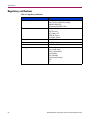
Regulatory certifications. . . . . . . . . . . . . . . . . . . . . . . . . . . . . . . . . . . . . . . . . . . . . . . . . . . . . . . . . . . . . . . . . . .62
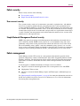
D Management System Requirements . . . . . . . . . . . . . . . . . . . . . . . . . . . . . . . . . . . . . . . . . . . . . . . . 63
Management system requirements . . . . . . . . . . . . . . . . . . . . . . . . . . . . . . . . . . . . . . . . . . . . . . . . . . . . . . . . . . .63
Cable pin configurations. . . . . . . . . . . . . . . . . . . . . . . . . . . . . . . . . . . . . . . . . . . . . . . . . . . . . . . . . . . . . . . . . . .64
Indirect Ethernet cable . . . . . . . . . . . . . . . . . . . . . . . . . . . . . . . . . . . . . . . . . . . . . . . . . . . . . . . . . . . . . . . . .64
Direct Ethernet cross-over cable . . . . . . . . . . . . . . . . . . . . . . . . . . . . . . . . . . . . . . . . . . . . . . . . . . . . . . . . .64
Serial cable. . . . . . . . . . . . . . . . . . . . . . . . . . . . . . . . . . . . . . . . . . . . . . . . . . . . . . . . . . . . . . . . . . . . . . . . . .64
Establishing an Ethernet or serial connection. . . . . . . . . . . . . . . . . . . . . . . . . . . . . . . . . . . . . . . . . . . . . . . . . . .65
Ethernet connection information . . . . . . . . . . . . . . . . . . . . . . . . . . . . . . . . . . . . . . . . . . . . . . . . . . . . . . . . .65
Serial connection information . . . . . . . . . . . . . . . . . . . . . . . . . . . . . . . . . . . . . . . . . . . . . . . . . . . . . . . . . . .66

Contents
6 HP StorageWorks 2/8q Fibre Channel Switch Installation Guide
Index . . . . . . . . . . . . . . . . . . . . . . . . . . . . . . . . . . . . . . . . . . . . . . . . . . . . . . . . . . . . . . . . . . . . . . 67
Figures
1 Chassis features . . . . . . . . . . . . . . . . . . . . . . . . . . . . . . . . . . . . . . . . . . . . . . . . . . . . . . . . . . . . . . . . . . . . . 13
2 Chassis LEDs . . . . . . . . . . . . . . . . . . . . . . . . . . . . . . . . . . . . . . . . . . . . . . . . . . . . . . . . . . . . . . . . . . . . . . . 14
3 Ethernet port and LEDs . . . . . . . . . . . . . . . . . . . . . . . . . . . . . . . . . . . . . . . . . . . . . . . . . . . . . . . . . . . . . . . 15
4 Fibre Channel port and LED locations. . . . . . . . . . . . . . . . . . . . . . . . . . . . . . . . . . . . . . . . . . . . . . . . . . . . 17
5 Switch carton contents . . . . . . . . . . . . . . . . . . . . . . . . . . . . . . . . . . . . . . . . . . . . . . . . . . . . . . . . . . . . . . . . 28
6 Using the rack template . . . . . . . . . . . . . . . . . . . . . . . . . . . . . . . . . . . . . . . . . . . . . . . . . . . . . . . . . . . . . . . 29
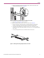
7 Attaching the right rail to the rack - rear view. . . . . . . . . . . . . . . . . . . . . . . . . . . . . . . . . . . . . . . . . . . . . . 30
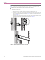
8 Moving the rail retaining bracket on the right rail - rear view. . . . . . . . . . . . . . . . . . . . . . . . . . . . . . . . . . 31
9 Attaching the mounting adapter brackets to the switch . . . . . . . . . . . . . . . . . . . . . . . . . . . . . . . . . . . . . . . 31
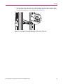
10 Placing the switch on the rails - rear view . . . . . . . . . . . . . . . . . . . . . . . . . . . . . . . . . . . . . . . . . . . . . . . . . 32
11 Securing the switch flanges to the rear of the rack . . . . . . . . . . . . . . . . . . . . . . . . . . . . . . . . . . . . . . . . . . 32
12 Securing the rail retaining brackets to the switch - front view . . . . . . . . . . . . . . . . . . . . . . . . . . . . . . . . . 33
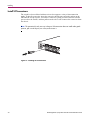
13 Installing an SFP transceiver . . . . . . . . . . . . . . . . . . . . . . . . . . . . . . . . . . . . . . . . . . . . . . . . . . . . . . . . . . . 34
14 Heartbeat LED location and blinking patterns. . . . . . . . . . . . . . . . . . . . . . . . . . . . . . . . . . . . . . . . . . . . . . 42
15 Logged-In LED location and blinking patterns . . . . . . . . . . . . . . . . . . . . . . . . . . . . . . . . . . . . . . . . . . . . . 44
16 Chassis LEDs . . . . . . . . . . . . . . . . . . . . . . . . . . . . . . . . . . . . . . . . . . . . . . . . . . . . . . . . . . . . . . . . . . . . . . . 46
Tables
1 Document conventions. . . . . . . . . . . . . . . . . . . . . . . . . . . . . . . . . . . . . . . . . . . . . . . . . . . . . . . . . . . . . . . . . 8
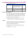
2 Zoning database limits . . . . . . . . . . . . . . . . . . . . . . . . . . . . . . . . . . . . . . . . . . . . . . . . . . . . . . . . . . . . . . . . 22
3 Environmental requirements . . . . . . . . . . . . . . . . . . . . . . . . . . . . . . . . . . . . . . . . . . . . . . . . . . . . . . . . . . . 27
4 Fabric specifications. . . . . . . . . . . . . . . . . . . . . . . . . . . . . . . . . . . . . . . . . . . . . . . . . . . . . . . . . . . . . . . . . . 59
5 Maintainability options . . . . . . . . . . . . . . . . . . . . . . . . . . . . . . . . . . . . . . . . . . . . . . . . . . . . . . . . . . . . . . . 60
6 Fabric management options and requirements. . . . . . . . . . . . . . . . . . . . . . . . . . . . . . . . . . . . . . . . . . . . . . 60
7 2/8q FC Switch chassis dimensions. . . . . . . . . . . . . . . . . . . . . . . . . . . . . . . . . . . . . . . . . . . . . . . . . . . . . . 61
8 Electrical requirements. . . . . . . . . . . . . . . . . . . . . . . . . . . . . . . . . . . . . . . . . . . . . . . . . . . . . . . . . . . . . . . . 61
9 Environmental requirements . . . . . . . . . . . . . . . . . . . . . . . . . . . . . . . . . . . . . . . . . . . . . . . . . . . . . . . . . . . 61
10 Regulatory certifications . . . . . . . . . . . . . . . . . . . . . . . . . . . . . . . . . . . . . . . . . . . . . . . . . . . . . . . . . . . . . . 62
11 Workstation requirements . . . . . . . . . . . . . . . . . . . . . . . . . . . . . . . . . . . . . . . . . . . . . . . . . . . . . . . . . . . . . 63
12 Ethernet and serial Cable Pin Configurations . . . . . . . . . . . . . . . . . . . . . . . . . . . . . . . . . . . . . . . . . . . . . . 64

7HP StorageWorks 2/8q Fibre Channel Switch Installation Guide
About This Guide
About this Guide
About this Guide
About this Guide topics include:
■ Intended audience, page 7
■ Related documentation, page 7
■ Document conventions, page 8
■ Text symbols, page 8
■ Equipment symbols, page 9
■ Rack stability, page 10
■ Getting help, page 10
Intended audience
This guide is intended for use by the system administrator responsible for the 2/8q FC Switch
and the MSA1000 storage system.
Related documentation
The following MSA1000 SAN Kit and 2/8q FC Switch documents are on the MSA1000 Small
Business SAN documentation CD:
■ HP StorageWorks Modular Smart Array 1000 Small Business SAN Kit Installation
Instructions (also printed)
■ HP StorageWorks 2/8q Fibre Channel Switch Management User Guide
■ HP StorageWorks 2/8q Fibre Channel Switch SNMP Reference Guide
■ HP StorageWorks 2/8q Fibre Channel Switch Event Messages Reference Guide
The following MSA1000-specific documents are on the MSA1000 documentation CD:
■ HP StorageWorks MSA1000 Configuration Overview
■ HP StorageWorks MSA1000 Installation Guide
■ HP StorageWorks Modular Smart Array 1000 Maintenance and Service Guide
■ HP StorageWorks Modular Smart Array 1000/1500 cs Command Line Interface User
Guide
■ HP StorageWorks Modular Smart Array 1000 Controller Reference Guide
■ HP Array Configuration Utility User Guide

About this Guide
8 HP StorageWorks 2/8q Fibre Channel Switch Installation Guide
Document conventions
This document follows the conventions in Table 1.
Text symbols
The following symbols may be found in the text of this guide. They have the following
meanings:
WARNING: Text set off in this manner indicates that failure to follow directions in the
warning could result in bodily harm or death.
Caution: Text set off in this manner indicates that failure to follow directions could result in
damage to equipment or data.
Tip: Text in a tip provides additional help to readers by providing nonessential or optional
techniques, procedures, or shortcuts.
Note: Text set off in this manner presents commentary, sidelights, or interesting points of
information.
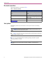
Table 1: Document conventions
Convention Element
Blue text: Figure 1 Cross-reference links
Bold Menu items, buttons, and key, tab, and box
names
Italics
Text emphasis and document titles in body text
Monospace font User input, commands, code, file and
directory names, and system responses (output
and messages)
Monospace, italic font Command-line and code variables
Blue underlined sans serif font text
(
http://www.hp.com
)
Web site addresses

About this Guide
9HP StorageWorks 2/8q Fibre Channel Switch Installation Guide
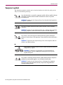
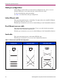
Equipment symbols
The following equipment symbols may be found on hardware for which this guide pertains.
They have the following meanings:
Any enclosed surface or area of the equipment marked with these symbols indicates
the presence of electrical shock hazards. Enclosed area contains no operator
serviceable parts.
WARNING: To reduce the risk of personal injury from electrical shock hazards, do
not open this enclosure.
Any RJ-45 receptacle marked with these symbols indicates a network interface
connection.
WARNING: To reduce the risk of electrical shock, fire, or damage to the equipment,
do not plug telephone or telecommunications connectors into this receptacle.
Any surface or area of the equipment marked with these symbols indicates the
presence of a hot surface or hot component. Contact with this surface could result in
injury.
WARNING: To reduce the risk of personal injury from a hot component, allow the
surface to cool before touching.
Power supplies or systems marked with these symbols indicate the presence of
multiple sources of power.
WARNING: To reduce the risk of personal injury from electrical shock,
remove all power cords to completely disconnect power from the power
supplies and systems.
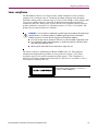
Any product or assembly marked with these symbols indicates that the component
exceeds the recommended weight for one individual to handle safely.
WARNING: To reduce the risk of personal injury or damage to the equipment,
observe local occupational health and safety requirements and guidelines for
manually handling material.

About this Guide
10 HP StorageWorks 2/8q Fibre Channel Switch Installation Guide
Rack stability
Rack stability protects personnel and equipment.
WARNING: To reduce the risk of personal injury or damage to the equipment, be sure
that:
■ The leveling jacks are extended to the floor.
■ The full weight of the rack rests on the leveling jacks.
■ In single rack installations, the stabilizing feet are attached to the rack.
■ In multiple rack installations, the racks are coupled.
■ Only one rack component is extended at any time. A rack may become unstable if
more than one rack component is extended for any reason.
Getting help
If you still have a question after reading this guide, contact an HP Authorized Service Provider
or access our web site:
http://www.hp .com
.
Note: HP call centers use product and serial numbers to validate warranty entitlement. Most HP
products can provide product number, serial number and firmware revision electronically through
the use of supplied management or diagnostic utilities, eliminating the need to physically inspect or
remove products from installed enclosures. You may be directed by HP to run these utilities to
gather required entitlement information.
HP installation and configuration assistance
A moderate level of SAN-related knowledge is required to successfully install this product. If
you are not familiar with installing and configuring storage array systems in a SAN, HP can
install it for you.
For more information, access our web site at
http://www.hp.com/hps/storage/ns_impleme ntation.html
.
Depending on your needs, different levels of assistance are available.
For example, the HP Installation and Startup for HP StorageWorks Disk Arrays Service
Package includes:
■ Physical installation of the MSA
■ Virtual disk design and configuration of the MSA
■ Service planning
■ Service deployment
■ Installation Verification Testing (IVT)
■ Customer orientation

About this Guide
11HP StorageWorks 2/8q Fibre Channel Switch Installation Guide
HP technical support
Telephone numbers for worldwide technical support are listed on the following HP web site:
http://www.hp.com/ support/
. From this web site, select the country of origin.
Note: For continuous quality improvement, calls may be recorded or monitored.
Be sure to have the following information available before calling:
■ Technical support registration number (if applicable)
■ Product serial numbers
■ Product model names and numbers
■ Applicable error messages
■ Operating system type and revision level
■ Detailed, specific questions
HP storage web site
The HP web site has the latest information on this product, as well as the latest drivers. Access
storage at:
http://www.hp.co m /c ountry/us/eng/prodserv/storag e.html
. From this web site,
select the appropriate product or solution.
HP authorized reseller
For the name of your nearest HP Authorized Reseller:
■ In the United States, call 1-800-282-6672
■ In Canada, call 1-800-863-6594
■ Elsewhere, see the HP web site for locations and telephone numbers:
http://www.hp.com
.


13HP StorageWorks 2/8q Fibre Channel Switch Installation Guide
1
Introduction
This chapter describes switch features, including the LEDs, user controls, and connections. An
overview of the switch management tools is also provided.
Included sections:
■ Switch chassis features, page 13
■ Switch management, page 19
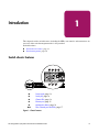
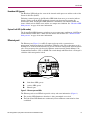
Switch chassis features
Figure 1: Chassis features
1 Power supply, page 14
2 Serial port, page 14
3 Chassis LEDs, page 14
4 Ethernet port, page 15
5 Maintenance button, page 16
6,7 Fibre Channel ports and LEDs, page 17
1 2 3 4
5 6 7

Introduction
14 HP StorageWorks 2/8q Fibre Channel Switch Installation Guide
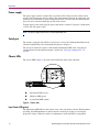
Power supply
The power supply converts standard 110 or 230 VAC to DC voltages for the various switch
circuits. Four internal fans provide cooling. The switch monitors internal air temperature, and
therefore does not monitor or report fan operational status. Air flows into the switch from the
bezel side and is exhausted from the port side of the switch.
To apply power to the switch, plug the power cord into the switch AC receptacle, and then into
a 110 or 230 VAC power source.
Note: The power supply and fans are not field replaceable units.
Serial port
The switch is equipped with an RS-232 serial port, to access the Command Line Interface for
advanced configuration tasks and maintenance purposes. (Figure 1)
The serial port connector requires a null-modem female/female DB9 cable, using the pin
configuration and connection information as detailed in “Cable pin configurations” on
page 64.
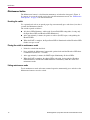
Chassis LEDs
The chassis LEDs (Figure 2) provide status information about switch operation.
Figure 2: Chassis LEDs
Input Power LED (green)
The Input Power LED indicates the voltage status at the switch logic circuitry. During normal
operation, this LED illuminates to indicate that the switch logic circuitry is receiving the
proper DC voltages. When the switch is in maintenance mode, this LED is extinguished.
1 Input Power LED (green)
2 Heartbeat LED (green)
3 System Fault LED (amber)
1
2
3

Introduction
15HP StorageWorks 2/8q Fibre Channel Switch Installation Guide
Heartbeat LED (green)
The Heartbeat LED indicates the status of the internal switch processor and the results of the
Power On Self Test (POST).
Following a normal power-up, the Heartbeat LED blinks about once per second to indicate
that the switch passed the POST and that the internal switch processor is running. In
maintenance mode, the Heartbeat LED illuminates continuously. The Heartbeat LED also
shows a blink code for POST errors and the over temperature condition. See “Heartbeat LED
blink patterns” on page 42 for more information.
System Fault LED (solid amber)
The System Fault LED illuminates to indicate an over temperature condition or a POST error
and the Heartbeat LED shows a blink code that defines the condition. See “Heartbeat LED
blink patterns” on page 42 for more information.
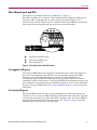
Ethernet port
The Ethernet port (Figure 3) is an RJ-45 connector that provides a connection to a
management workstation through a 10/100 Base-T Ethernet cable. The workstation can be a
Windows® or a Linux® workstation that is used for advanced configuration and management
tasks. You can manage the switch over the Ethernet connection using Switch Manager, the
Command Line Interface (CLI), or SNMP. The switch through which the fabric is managed is
called the fabric management switch.
Figure 3: Ethernet port and LEDs
The Ethernet port has two LEDs that provide activity and status information. (Figure 3)
■ The Activity LED illuminates when data is being transmitted or received.
■ The Link Status LED illuminates continuously when an Ethernet connection has been
established.
1 Link Status LED (green)
2 Activity LED (green)
3 Ethernet port
1
3
2

Introduction
16 HP StorageWorks 2/8q Fibre Channel Switch Installation Guide
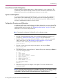
Maintenance button
The Maintenance button is a dual-function momentary switch on the front panel. (Figure 1)
Its purpose is to reset the switch or place the switch in maintenance mode. See “Maintenance
mode options” on page 47 for more information.
Resetting the switch
Use a pointed tool, such as an opened paper clip, to momentarily press and release (less than 2
seconds) the Maintenance button.
The switch responds as follows:
■ All chassis LEDs illuminate, and then the System Fault LED extinguishes, leaving only
the Input Power LED and Heartbeat LED illuminated.
■ After approximately 1 minute, the power-on self test (POST) begins, extinguishing the
Heartbeat LED.
■ When the POST is complete, the Input Power LED is illuminated and the Heartbeat LED
flashes once per second.
Placing the switch in maintenance mode
1. Isolate the switch from the fabric.
2. Press and hold the Maintenance button with a pointed tool until the Heartbeat LED alone
is illuminated (between 2–7 seconds).
3. After approximately 1 minute, the POST begins illuminating all chassis LEDs.
4. When the POST is complete, the chassis LEDs extinguish, leaving only the Heartbeat
LED illuminated. The Heartbeat LED illuminates continuously while the switch is in
maintenance mode.
Exiting maintenance mode
To exit maintenance mode and return to normal operation, momentarily press and release the
Maintenance button to reset the switch.

Introduction
17HP StorageWorks 2/8q Fibre Channel Switch Installation Guide
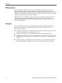
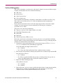
Fibre Channel ports and LEDs
The switch has eight Fibre Channel ports, numbered 0–7. (Figure 4)
Each Fibre Channel port is served by a 2 Gbps Small Form-Factor Pluggable (SFP) optical
transceiver. SFPs are hot-pluggable. User ports self-discover both the port type and
transmission speed of the connected devices. The Fibre Channel port LEDs are located above
their respective ports and provide port log-in and activity status information.
Figure 4: Fibre Channel port and LED locations
Port Logged-in LED (green)
The Logged-in LED indicates the logged-in or initialization status of the connected devices.
After successful completion of the POST, the switch extinguishes all Logged-in LEDs.
Following a successful loop initialization or port login, the switch illuminates the
corresponding logged-in LED. This shows that the port is properly connected and able to
communicate with its attached devices. The Logged-in LED remains illuminated as long as the
port is initialized or logged in. If the port connection is broken or an error occurs that disables
the port, the Logged-in LED flashes. See “Logged-In LED indications” on page 44 for more
information.
Port Activity LED (green)
The Activity LED indicates that data is passing through the port. Each frame that the port
transmits or receives causes this LED to illuminate for 50 milliseconds. This makes it possible
to observe the transmission of a single frame. When extending credits, the Activity LED for a
donor port will reflect the traffic of the recipient port. See “Distance” on page 24 for more
information about extended credits and donor ports.
1 Port Logged-in LED (green)
2 Port Activity LED (green)
3 Fibre Channel port
1 2 3

Introduction
18 HP StorageWorks 2/8q Fibre Channel Switch Installation Guide
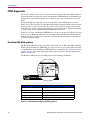
SFP transceivers
The switch supports SFP optical transceivers for the Fibre Channel ports. A transceiver
converts electrical signals to and from optical laser signals to transmit and receive data.
Duplex fiber optic cables plug into the transceivers, which then connect to the devices. A Fibre
Channel port is capable of transmitting at 1 Gbps or 2 Gbps; however, the transceiver must be
capable of 2 Gbps for the port to deliver at that rate.
SFP transceivers are hot pluggable. This means that you can remove or install a transceiver
while the switch is operating, without harming the switch or the transceiver. However,
communication with the connected device is interrupted. See “Install SFP transceivers” on
page 34 for information.
Port types
The switch supports generic ports (G_Port, GL_Port) and fabric ports (F_Port, FL_Port).
Switches come from the factory with all Fibre Channel ports configured as GL_Ports.
Ports function as follows:
■ A GL_Port self-configures as an FL_Port when connected to a public loop device, and as
an F_Port when connected to a single public device.
■ A G_Port self-configures as an F_Port when connected to a single public device.
■ An FL_Port supports a loop of up to 126 public devices. An FL_Port can also configure
itself during the fabric login process as an F_Port when connected to a single public device
(N_Port).
■ An F_Port supports a single public device. If the device is a single device on a loop, the
GL_Port will attempt to configure first as an F_Port, then if that fails, as an FL_Port.

Introduction
19HP StorageWorks 2/8q Fibre Channel Switch Installation Guide
Switch management
Fabrics are managed with following tools:
■ Switch Manager user interface
■ Command Line Interface
■ File Transfer Protocol
■ Simple Network Management Protocol
Switch Manager user interface
Switch Manager is a workstation-based Java® application that provides a graphical user
interface for fabric management. This application runs on a Windows or Linux workstation. A
management workstation connects to the fabric through the Ethernet port of one or more
switches and can provide in-band management for all other switches in the fabric. See
“Management System Requirements” on page 63 for connection information and to the HP
StorageWorks 2/8q Fibre Channel Switch Management User Guide for information about
Switch Manager.
Command Line Interface
The CLI provides monitoring and configuration functions by which the administrator can
manage the fabric and its switches, and can be accessed over an Ethernet connection or a serial
connection. See “Management System Requirements” on page 63 for connection information
and refer to the HP StorageWorks 2/8q Fibre Channel Switch Management User Guide for
information about the CLI.
File Transfer Protocol
FTP provides the command line interface for exchanging files between the switch and the
management workstation. These files include firmware image files, configuration files, and
log files.
Simple Network Management Protocol
SNMP provides monitoring and trap functions for the fabric. This switch supports SNMP
versions 1 and 2, the Fibre Alliance Management Information Base (FA-MIB) version 4.0, and
the Fabric Element Management Information Base (FE-MIB) RFC 2837. Traps can be
formatted using SNMP version 1 or 2. Refer to the HP StorageWorks 2/8q Fibre Channel
Switch SNMP Reference Guide for more information.

Page is loading ...
Page is loading ...
Page is loading ...
Page is loading ...
Page is loading ...
Page is loading ...
Page is loading ...
Page is loading ...
Page is loading ...
Page is loading ...
Page is loading ...
Page is loading ...
Page is loading ...
Page is loading ...
Page is loading ...
Page is loading ...
Page is loading ...
Page is loading ...
Page is loading ...
Page is loading ...
Page is loading ...
Page is loading ...
Page is loading ...
Page is loading ...
Page is loading ...
Page is loading ...
Page is loading ...
Page is loading ...
Page is loading ...
Page is loading ...
Page is loading ...
Page is loading ...
Page is loading ...
Page is loading ...
Page is loading ...
Page is loading ...
Page is loading ...
Page is loading ...
Page is loading ...
Page is loading ...
Page is loading ...
Page is loading ...
Page is loading ...
Page is loading ...
Page is loading ...
Page is loading ...
Page is loading ...
Page is loading ...
Page is loading ...
Page is loading ...
-
 1
1
-
 2
2
-
 3
3
-
 4
4
-
 5
5
-
 6
6
-
 7
7
-
 8
8
-
 9
9
-
 10
10
-
 11
11
-
 12
12
-
 13
13
-
 14
14
-
 15
15
-
 16
16
-
 17
17
-
 18
18
-
 19
19
-
 20
20
-
 21
21
-
 22
22
-
 23
23
-
 24
24
-
 25
25
-
 26
26
-
 27
27
-
 28
28
-
 29
29
-
 30
30
-
 31
31
-
 32
32
-
 33
33
-
 34
34
-
 35
35
-
 36
36
-
 37
37
-
 38
38
-
 39
39
-
 40
40
-
 41
41
-
 42
42
-
 43
43
-
 44
44
-
 45
45
-
 46
46
-
 47
47
-
 48
48
-
 49
49
-
 50
50
-
 51
51
-
 52
52
-
 53
53
-
 54
54
-
 55
55
-
 56
56
-
 57
57
-
 58
58
-
 59
59
-
 60
60
-
 61
61
-
 62
62
-
 63
63
-
 64
64
-
 65
65
-
 66
66
-
 67
67
-
 68
68
-
 69
69
-
 70
70


HP STORAGEWORKS A7540-96010 User manual
- Category
- Network switches
- Type
- User manual
- This manual is also suitable for
Ask a question and I''ll find the answer in the document
Finding information in a document is now easier with AI
Related papers
Other documents
-
Compaq d230 - Microtower Desktop PC Safety And Regulatory Information Manual
-
-
-
-
-
-
-
Compaq StorageWorks b3000 v2 Quick start guide
-
-