Page is loading ...

1. READ INSTRUCTIONS - All safety and operating instructions should be read before the appliance is operated.
2. RETAININSTRUCTIONS - Safety and operating instructions should be retained for future reference.
3. HEED W ARNINGS - All warnings on the appliance and in operating instructions should be adhered to.
4. FO LLO W INSTRUCTIONS - All operating and use instructions should be follow ed.
5. WATERANDMOISTURE- The appliance should not be used near water - near bathtub, washbow l, kitchen sink, laundry tub; in a wet basem ent near
a sw imming pool, etc.
6. CARTS AND STANDS - Do not place this product on an unstable cart, stand, tripod, bracket, or table. The appliance should be used only with a cart
or stand that is recom m ended by the m anufacturer.
7. VENTILATION - The appliance should be situated so that its location and position do not interfere with proper ventilation. The appliance should not
be situated on a bed, sofa, rug, or any surface that may obstruct cabinet openings.
8. HEAT - The appliance should be situated aw ay from heat sources such as radiators, heat registers, stoves, or other devices (including am plifiers) that
produce heat.
9. POW ER SOURCES - This product should be operated only from the type of pow er source indicated on the marking label. If you are not sure of the
type power supply in your hom e, consult your product dealer or local power com pany. For products intended to operate from battery power or other
sources, refer to the operating instructions.
10. POWERCORDPROTECTION - Power supply cords should be routed so that they are not likely to be walked upon or pinched by item s placed upon
or against them , paying attention to cords and plugs, convenience receptacles, and the point where they exit from the appliance.
11. POLARIZED PLUG - This appliance is equipped with a polarized line plug (a plug having one blade wider than the other). This plug will fit into the
power outlet only one way. This is a safety feature. If you are unable to insert the plug fully into the outlet, try reversing the plug. If the plug still fails to
fit, contact your electrician to replace your obsolete outlet. Do not attem pt to defeat this safety feature.
12. LIGHTNING - For added protection for this product during a lightning storm, or when it is left unattended and unused for long periods of time, unplug
it from the wall outlet and disconnect the antenna or cable system . This will prevent dam age to the product due to lightning and pow er line surges.
13. OVERLOADING - Do not overload wall outlets, extension cords, or integral convenience receptacles, as this can result in a risk of fire or electric-
shock.
14. CLEANING - U nplug this product from the wall outlet before cleaning. Do not use liquid cleaners or aerosol cleaners. Use a dam p cloth for cleaning.
15. NON-USE PERIODS - This am plifier should be unplugged from the outlet when the appliance is left unused for a long period of time.
16. OBJECTAND LIQUIDENTRY - Never push objects of any kind into this product through openings, as they may touch dangerous voltage points or
short-out parts that could result in a fire or electric shock. Never spill liquid of any kind on this product.
17. DAMAGE REQUIRING SERVICE - The appliance should be serviced by qualified personnel w hen:
a. The power supply cord or plug has been dam aged; or
b. Objects have fallen on or liquid has been spilled into the appliance; or
c. The appliance has been exposed to rain; or
d. The appliance does not appear to operate normally or exhibits a marked change in perform ance; or
e. The appliance has been dropped or the enclosure is dam aged.
18. SERVICING - D o not attem pt to service this product yourself, as opening or rem oving covers m ay expose you to dangerous voltage or other
hazards. Refer all servicing to qualified service personnel. For service warranty information call the NHT Hotline num ber: 1-800-NHT-9993.
19. REPLACEMENT PARTS - W hen replacem ent parts are required, be sure the service technician has used replacem ent parts specified by the m anu-
facturer or that have the sam e characteristics as the original part. Unauthorized substitution may result in fire, electric shock, or other hazards.
20. SAFETY CHECK - U pon com pletion of any service or repairs to this product, ask the service technician to perform safety checks to determine that
the product is in proper operating condition.
IMPORTANT SAFETY INSTRUCTIONS
The lightning flash with the arrow head sym bol, within an equilateral triangle, is intended to alert the user to the presence of uninsulated
“dangerous voltage” within the product’s enclosure that may be of sufficient m agnitude to constitute a risk of electric shock to persons.
The exclam ation point within an equilateral triangle is intended to alert the user to the presence of im portant operating and maintenance
(servicing) instructions in the literature accom panying the appliance.
W ARNING: TO REDUCE THE RISK OF FIRE OR ELECTRIC SHOCK, DO NOT EXPOSE THIS APPLIANCE TO RAIN OR MOISTURE.
CAUTION
RISK OF ELECTRIC SHOCK
DO NOT OPEN
CAUTION: TO REDUCE RISK OF ELECTRICAL SHOCK, DO NOT REMOVE COVER (OR BACK). NO
USER SERVICEABLE PARTS INSIDE. REFER TO QUALIFIED SERVICE PERSONNEL.
CAUTION
TO PREVENT ELECTRIC SHOCK, DO NOT USE THIS (POLARIZED) PLUG WITH AN EXTENSION CORD,
RECEPTACLE OR OTHER OUTLET UNLESS THE BLADES CAN BE FULLY INSERTED TO PREVENT
BLADE EXPOSURE.

is to rem em ber that low frequencies produce sounds with
long wavelengths, which interact in com plex ways with
room boundaries, such a w alls and corners, and other
large objects as well.
Placing the subw oofer near to a room boundary will tend
to increase its apparent bass output, but may result in
"boom y" or "m uddy" sound. C onversely, placing it farther
away from room boundaries w ill tend to decrease its
apparent bass output, but may result in improved
articulation and clarity.
W hen possible, place the subw oofer in the sam e
horizontal plane and along the sam e wall as the m ain
speakers.
And since sm all changes in subw oofer position can have
a significant effect on sound, experim enting w ith the
effects of different placem ents in your own listening/view -
ing room is the key to finding the sound you like best.
SW 10 ll and SW 12 Features & Contro ls
Volum e: This control allow s you to adjust the gain of the
Subw oofer relative to the rest of your system . M any lis-
teners make the mistake of setting subw oofers too loud,
which can cause excess bloat and loss of detail and
musicality. A properly calibrated subwoofer blends in with
the speakers and does not call attention to itself. To
properly set volum e:
• Turn down the volum e control on the SW 10 ll or SW 12
to its low est position (counter-clockw ise).
• T u rn on your audio system , including the SW 10 ll or
SW 12. Play some music you are fam iliar with and set
your receiver/pream plifier volum e to a com fortable lis-
tening level.
• Slowly increase the volum e of the SW 10 ll or SW 12, lis-
tening for proper frequency balance. W hen balanced,
you will hear improved bass extension, but not be aware
that it is com ing from the subwoofer.
From this point on, the volum e contro l on your
receiver/pream plifier will control the overall volum e of
your system , including the subw oofer.
The Boundary EQ: This is a feature unique to NHT
Evolution products. Reflective boundaries (such as
walls) reinforce a speaker’s bass output (3dB for two
walls, 6dB for a corner) if the subw oofer is placed near
them . Conversely, placing a subw oofer out in the room
results in a relative decrease in bass output. Boundary
reinforcem ent may lead to low frequency response that
Thank you for your purchase of the N HT
SW 10 ll or SW 12 pow ered subw oofer.
Like all NHT loudspeakers, the SW 10 ll and SW 12's
developm ent has been guided by the study of hum an
hearing, it’s design rigorously tested, and its com ponents
optimized to deliver clean, clear musical sound.
Since the quality of your speakers is one of the m ost
im portant factors in maximizing the sound you'll get from
your music and hom e theater system , we're sure that
you'll find your purchase of the SW 10 ll and SW 12 a
good investm ent, and invite your com m ents.
If you find your experience with the SW 10 ll and SW 12
as satisfying as we believe you will, and wish to enjoy its
high quality sound through your entire system , you'll find
information about other sonically m atched NHT Super
Series loudspeakers on the back of this m anual.
Background
The NHT SW 10 ll and SW 12 Powered Subw oofer is a
com pact, versatile and pow erful am plified subwoofer
designed to provide low frequency reinforcem ent for high
perform ance audio and hom e theater system s.
The SW 10 ll and SW 12 features:
• line-level and speaker-level inputs, for connection with
all types of receivers or other audio com ponents
• independent gain, phase and low pass filter controls
• boundary control for adjusting system sound for various
room placem ent
Please take a few m inutes to read through this owner's
m anual before setting up your speakers; this information
will help you get the most out of them . Also, please keep
the SW 10 ll or Sw 12’s packaging to use in case you
move or transport them .
If you have questions at any tim e during setup or use,
feel free to call your N HT dealer or our Toll-Free
Custom er Hotline at 1-800-NHT-9993.
Placem ent
Note: To prevent the SW 10 ll and SW 12 subw oofer
am plifier from overheating, alw ays be sure to provide
adequate space for proper ventilation. Do not place the
subw oofer directly against the wall or any other surface.
The key to placing your subwoofer for optimal enjoym ent

is uneven. S om e frequencies w ill sound exaggerated
relative to others, or the subw oofer will sound thin and
lack im pact. The Boundary E Q control allows you to
com pensate for the effects of room boundaries on the
frequency response
of the subw oofer. A djusting the control enables you to
achieve sm ooth low frequency output from the sub-
woofer regardless of its location in your room .
The follow ing diagram s shown in Fig. 1 show the corre-
lation betw een subwoofer placem ent and Boundary EQ.
These diagram s are guidelines only. Your room
acoustics and personal tastes w ill ultimately dictate the
final setting.
LOW PASS FILTER :This control determines the upper-
limit frequency the subw oofer w ill reproduce. For
exam ple, setting the filter at 100Hz w ill cause the
subw oofer to reproduce only frequencies below 100Hz.
The Low Pass Filter is continuously variable betw een
40Hz (low bass) and 180Hz (upper bass), to
accom m odate different speakers.
Tw o tips on using the Low Pass Filter:
As a starting point, set Low Pass Filter to the 1 o’clock
position. This will result in an 80Hz low pass. As the set-
ting is typical for most Dolby D igital / D TS applications.
Note: The LFE input bypasses the adjustable 12dB Low
Pass Filter.
See the Fine-Tuning section for further adjustm ent
guidelines.
SUBW OOFER PHASE: This sw itch sets the phase of
the subw oofer at either the 0° position (normal phase) or
the 180° position (reverse phase) to achieve the
sm oothest possible bass response in your system .
This phase-reversing option is im portant because if bass
frequencies com e from both the subw oofer and the main
speakers, peaks and dips in the frequency response can
occur at the listening position. In these cases, reversing
the subwoofer phase can improve blending and balance.
To properly set the Subw oofer Phase:
• Play fam iliar music, reversing phase settings. And listen
from your usual position.
• Avoid evaluating while standing above the subw oofer or
am plifier; sound at the listening position w ill be
significantly different.
• The correct setting is the one in which the bass is the
loudest at the listening position.
POW ER MODE: This feature autom atically sw itches
your SW 10 ll or SW 12 into m inimum-power m ode (ie,
sleep) w henever no signal is present for 20 m inutes.
W hen a signal is received, it im m ediately turns on again.
As AU TO M ode is autom atic, it requires no adjustm ent,
nor is there a need to turn the SW 10 ll or SW 12 on and
off every time it is used. W hen in O N M ode, the sub-
woofer is alw ays on.
+3dB
-3dB
0
Boundary
+3dB
-3dB
0
Boundary
+3dB
-3dB
0
Boundary
Quarter/
Half
Space
Half
Space
Half/
W hole
Space
Fig. 1

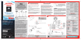
Back of Subwoofer (refer to diagram above)
(1) Power M ode - Leaves Subw oofer in perm anantly on
(ON), or puts the subwoofer in autom atic standby m ode
(AUTO).
(2) Power Indicator - The light is green w hen the sub-
woofer is on. The light is am ber w hen the subw oofer is in
stand-by m ode. The light is red w hen the subw oofer is in
protection.
(3) Volum e Contro l - Adjusts the loudness of the sub-
woofer independently of the main speakers.
(4) Low-Pass Filter - C ontinuously variable low -pass
crossover control.
(5) Boundary Sw itch - Selects response m ode of sub-
woofer, depending on placem ent.
(6) Subw oofer Phase Selector - 2-position selectable
phase control for subwoofer. (0 - 180)
(7) Line Input- Low level RCA input jacks for L/R signals
(8) LFE In/Out- Low level RCA input jack for LFE or sub-
woofer signal. Out is an unbuffered pass through used
for multiple subw oofers.
(9) Hi Level Input- Speaker level input connector.
(10) Power Switch -Turns the unit on and off
(11) Fuse Holder - location of the user servicable fuse
(12) Power Inlet - For universal AC line input connection
(13) Input Voltage Sw itch - Selects 115 VAC or 230
VAC mains voltage.
Connecting The SW 10II OR SW 12
Caution: Before connecting the SW 10II O R SW 12 to
your audio system , it is im portant to unplug or turn off
all AC power connections to connected com ponents
such as receivers, am plifiers, pream plifiers, and proces-
sors. D o n ot plug in or connect the SW 10II OR SW12
subw oofer to AC power until all connections have been
m ade.
Integrating the SW 10II or SW 12 into your surround sys-
tem is simple and straightforward when using this con-
nection m ethod. Your AV Receiver will control all
crossover functions and the SW 10II or SW 12 will control
Subw oofer gain, phase and boundary equalization.
Connect the Subw oofer/LFE Output on your AV Receiver
to the LFE IN on the back of the SW 10II or SW 12. (Fig.
2)
In the event your receiver or pre-am p does not have a
LFE or Subw oofer output the SW 10II/SW 12 has two
additional connection methods:
1) Line Level
Use if:
You have an am p or receiver with Pre-Out jacks but no
LFE/Subwoofer jacks.
To connect for a Line Level signal (Fig. 3), keep your
main speakers connected as usual, but use R CA line-
level cables to connect as follow s:
115V 60Hz /
230V 50Hz~
300W
T3.0AL 250V
For 115 V
T2.0AL 250V
For 230V
Hi Level Input
Out R
InL
LFE
Low Pass
Filter
40Hz
+L--R+
Power
Mode
On
180
+3dB
-3dB
Auto
0
0
Phase
Boundary
180Hz
Min
Max
Volume
Power
On
Off
Line
Input
Input Voltage
CAUTION: FOR CONTINUED PROTECTION AGAINST
FIRE, REPLACE ONLY WITH SAME TYPE 250V FUSE
CAUTION
WARNING:
TO REDUCE THE RISK OFFIRE OR ELECTRIC
SHOCK, DO NOT EXPOSE THIS APPLIANCETO RAIN OR MOISTURE.
2001228
WARNING: SHOCK HAZARD-DO NOT OPEN.
AVIS: RISQUE DE CHOC ELECTRIQUE-NE PAS OUVRIR.
RISK OF ELECTRIC SHOCK
DO NOT OPEN
CONFORMS TO
ULSTD.6500
CERTIFIED TO
CAN/CSA
STD.E60065
Green - On
Red - Protect
Amber - Standby
115
Powered
Subwoofer
1
6
5
3
4789
2
10
11
12
13
CAUTION
WARNING:
TO REDUCE THE RISK OFFIRE OR ELECTRIC
SHOCK, DO NOT EXPOSE THIS APPLIANCETO RAIN OR MOISTURE.
WARNING: SHOCK HAZARD-DO NOT OPEN.
AVIS: RISQUE DE CHOC ELECTRIQUE-NE PAS OUVRIR.
RISK OF ELECTRIC SHOCK
DO NOT OPEN
CAUTION: FOR CONTINUED PROTECTION AGAINST
FIRE, REPLACE ONLY WITH SAME TYPE 250V FUSE
2001228
CONFORMS TO
ULSTD.6500
CERTIFIED TO
CAN/CSA
STD.E60065
LR
SPEAKER OUTPUTS
LFE / Sub
+
-
Reciever
Main Speakers
SW10 / SW12
Back of Subwoofer
Hi Level Input
Out R
InL
LFE
Low Pass
Filter
40Hz
+L--R+
Power
Mode
On
180
+3dB
-3dB
Auto
0
0
Phase
Boundary
180Hz
Min
Max
Volume
Line
Input
Fig. 2

• Pream ps with Line Out jacks: connect one pair of Line
Out cables to your main am p to pow er your main L & R
speakers, and a second pair to the SW 10II OR SW12
LINE LEVEL INPUT. If your pream p has only one pair of
Line O ut jacks, you can use a pair of "Y" connector
cords, available through your NHT dealer.
• Am ps and receivers w ith Pre-Out jacks: connect the
SW 10II OR SW 12 from the Pre-Out into the SW 10II OR
SW 12's Line Input.
2) Hi-Level
Use if:
Your receiver has no Pre O ut or Subwoofer/LFE O ut
jacks
To connect for a High-Level signal (Fig. 4), use two addi-
tional pairs of speaker cables, and connect as follow s:
• For am ps and receivers with separate A and B speak-
er outputs, connect one pair of speaker cables from your
receiver's Speaker A outputs to your main L & R speak-
ers, and a second pair from your receiver's Speaker B
outputs to the SW 10II OR SW 12's High-Level Input. Use
this method only if both A & B speaker outputs can oper-
ate simultaneously.
• For am ps and receivers w ith only one set of speaker
output terminals, simply feed the sam e signal, in parallel,
to both your main L & R speakers and the SW 10II OR
SW 12. C onnect one pair of speaker cables from your
com ponent's speaker output terminals to the L & R
speakers, and a second pair from the sam e output ter-
minals to the SW 10II OR SW 12's High-Level input. The
SW 10II OR SW 12's input does not present a significant
load to the receiver, and will not com prom ise its output to
the L & R speakers. If you find that your receiver will not
accom m odate more than one cable per output terminal,
check w ith your NH T dealer for alternative m ethods of
connection.
With all signal connections com plete, it is now time to
apply AC power. Plug the power chord into the pow er
inlet in the back of the subw oofer, plug the other end into
into the w all outlet and switch the subwoofers pow er to
the ON position.
L
L
R
R
SPEAKER OUTPUTS
Pre Out
+
-
Reciever
Main Speakers
SW10 / SW12
Back of Subwoofer
Hi Level Input
Out R
InL
LFE
Low Pass
Filter
40Hz
+L--R+
Power
Mode
On
180
+3dB
-3dB
Auto
0
0
Phase
Boundary
180Hz
Min
Max
Volume
Line
Input
Fig. 3
Out R
InL
LFE
Low Pass
Filter
40Hz
+L--R+
Power
Mode
On
180
+3dB
-3dB
Auto
0
0
Phase
Boundary
180Hz
Min
Max
Volume
Line
Input
SW10 / SW12
Back of Subwoofer
LEFT RIGHT
+ +
- -
Reciever
Main Speakers
SPEAKER OUTPUT SPEAKER OUTPUT
ut R
InL
LFE
Line
Input
Hi Level Input
Fig. 4

Fine Tuning the Subw oofer
The key to good subw oofer / speaker integration is
repeated listening, follow ed by m aking sm all re-adjust-
m ents of the subwoofer controls. The m ost im portant
bass tuning functions you will control are the LO W -PASS
FILTE R , follow ed by the VO LU M E CO N TRO L settings
and then PHASE SELECTOR.
The frequency chart below lists som e terms commonly
used to describe different bands of the frequency
spectrum . Listen to your system and make adjustm ents
to achieve a seam less blend betw een your m ain
speakers and the SW 10 ll or SW 12. Four com m on prob-
lem s are outlined below. Follow the flow chart to correct
these. See the glossary for any terms you are unfam iliar
with.
Frequency Chart
Low Bass Mid Bass Upper Bass Lower Mid Mid Upper Mid High
Below 50Hz 50H z-100Hz 100H z-180Hz
3K and above
180Hz-300Hz 300H z-700Hz 700H z-3K
"Boomy"
Too Much
Mid / Upper
Bass
Problem
Solution
Lacks
Low
Bass
Weight
Excessive
Low
Bass
Weight
Lacks
Mid / Upper Bass:
Lean But With
Weight
Fine Tuning Flow Chart
Lower
Low Pass
X-Over
Frequency
Increase
Boundary
EQ
Decrease
Boundary
EQ
Adjust
Subwoofer
Volume
Listen
If this makes
it worse,
try
If the sound
improves
Raise
Low-Pass
Setting
Adjust
Subwoofer
Volume
Adjust
Subwoofer
Phase
Listen
Lower
Subwoofer
Volume
Move
Subwoofer
Closer to
Wall
Move
Subwoofer
Farther
From Wall
Adjust
Subwoofer
Phase
0-90
(Continuously
Add)
Adjust
Subwoofer
Phase
0-90
(Continuously
Add)
Adjust
Subwoofer
Phase
Switch
0-180
Listen
Listen
Listen

O peration
We recom m end that the SW 10 ll or SW 12 pow er be left
on, which will allow the built-in Auto M ode feature to dis-
able the subw oofer w hen not in use.
Every speaker, has limits, and it's im portant to listen for
them . Speaker dam age most often results not from brief
loud musical peaks, but from sustained high volum e lev-
els in som e or all frequencies. F or this reason,
extrem e volum e settings and excessive bass, treble or
equalizer boosts are not recom m ended.
If you hear unusual distortion or breakup, or notice heat
com ing from the woofer, decrease volum e im m ediately,
neutralize any excess bass, treble or equalizer boosts,
and avoid setting any controls to similar extrem es again.
Maintenance
Your SW 10 ll and SW 12 is designed for years of use with
no or minimal maintenance, as long as you avoid expos-
ing it to direct sunlight, high tem peratures, or moisture.
Clean cabinets, w hen necessary, using a dam p cloth or
a m ild, non-abrasive cleaner; to clean grilles, rem ove
from speaker and use a soft brush or a vacuum on its
lowest setting. Do not attem pt to clean the actual driv-
er.
9.8 Changing the Line Voltage Setting
The SW 10 ll and SW 12 were designed to operate on two
line voltage settings, 115VAC and 230VAC. In the event
that it is necessary to change the line voltage setting,
begin by turning the pow er sw itch to the off position.
Remove all the connections from the am plifier, including
the detachable pow er cord. U sing a flat blade screw-
driver, slide the switch to the correct position. U se the
115VAC position for 110 to 120 VAC , and the 230VAC
position for 220 to 240 VAC. Next you will likely need a
power cord that fits the AC receptacle and you will need
to replace the fuse (see "C hanging the Fuse" below )
Changing the Fuse
The SW 10 ll and SW 12 am plifier's fuse is user-servicea-
ble.
To replace it:
• turn the pow er OFF
• unplug the power cord
• rem ove the fuse holder cover (above to the pow er inlet)
with a flat blade screwdriver
• rem ove the fuse from the holder and replace it with the
appropriate type.
• reinstall the fuse holder
Alw ays replace the fuse w ith one of the exact sam e
specifications.
SW 10 ll:
For system s operating at 115 volts, use only a 5x20 mm,
T3A, 250-volt slow -blow fuse.
For system s operating at 230 volts, use only a 5x20 mm,
T2.0A, 250-volt slow-blow fuse.
SW 12:
For system s operating at 115 volts, use only a 5x20 mm,
T5A, 250-volt slow -blow fuse.
For system s operating at 230 volts, use only a 5x20 mm,
T2.5A, 250-volt slow-blow fuse.
Troubleshooting
If the SW 10 ll or SW 12 fails to operate at all w hen the
Power Switch is turned on, thoroughly check the pow er
cord, input and output connections
If the SW 10 ll or SW 12 turns on but the LED indicator
fails to illum inate, mis-wiring or a pow er surge may have
caused the protection fuse to blow. R eplace it with one of
correct type and value.
If the SW 10 ll or SW 12 turns on but its status LED stays
red, the unit is gone into protect m ode, which could be
caused by incorrect wiring, short circuits, or excessive
volum e. Turn off the Power Switch on the subwoofer for
two or more seconds to reset, and double check all
speaker cables to be sure that no sm all metal strands are
shorting the terminals.
If these steps don't restore the SW 10 ll or SW 12 to oper-
ation, contact your local Authorized NHT Dealer or NHT
for assistance.
Satisfaction
Your satisfaction w ith your new N HT SW 10 ll or SW 12
Subw oofer is im portant to us. Please note the matched
products and accessories we provide for them , and your
warranty, printed on the back of this m anual. If you have
any questions regarding your speakers' use, feel free to
call NHT at 1-800-NHT-9993. E n joy your listening and
view ing!

Glossary
Active:Uses electrical power.
Amplifier: An electronic device that increases the cur-
rent and/or voltage of a signal, providing pow er to the
loudspeakers (i.e. power am plifier, integrated am plifier,
receiver).
Bass: The range of audio frequencies below 180Hz,
characterized by low pitch.
Crossover: An electronic circuit that divides an audio
signal into different frequency ranges.
Distortion:Any deviation from the original signal.
Driver:The moving part of a loudspeaker, which radiates
sound energy.
Dynamics:Variations in loudness of sound.
Frequency: A rate of vibration, which corresponds to
musical pitch, expressed in Hertz (Hz).
Full Range: A signal encom passing the entire audible
frequency spectrum .
Hertz (Hz):A unit equal to one cycle per second, used to
m easure the frequency of a signal or sound.
High-Pass Filter:A filter that passes only high frequen-
cies above a lower limit.
Im pedance:A m easure of the total opposition to current
flow in an alternating current circuit, m easured in ohm s.
In Phase:The polarity of an audio signal when connect-
ed as follow s: (+) to (+) and (-) to (-).
Integrated A m plifier: A pream plifier and am plifier built
into one chassis.
Interconnect Cable:A length of shielded wire with plugs
at both ends for feeding signals from one electronic
device to another.
L.F.E.:"Low Frequency Effects"; The .1 channel of infor-
mation recorded on most multichannel digital sound for-
mats.
Line-Level Connection:Low level RCA/phono or XLR
type connection.
Load: A term used to describe the im pedance that a
speaker presents to an am plifier.
Low-Pass Filter:A filter that passes only low frequen-
cies below a higher limit.
Main Speakers:Front L & R channel speakers, som e-
times referred to as satellites.
Main-In:A line-level RCA/XLR pow er am plifier input on
the back of a receiver, integrated am plifier or power
am plifier.
Midrange:The frequency span in the middle of the audio
range, roughly 180Hz - 3000Hz. A lso used to describe
the driver that reproduces these frequencies.
Ohm:A unit of electrical resistance. That which opposes
an electric current in a conductor. In audio, a m easure of
the load presented by a device to an electrical source.
Out-of-Phase: The polarity of an audio signal w hen
connected as follow s: (+) to (-) and (-) to (+).
Passive:Uses no electrical pow er.
Phase:An expression of the relative polarities of two sig-
nals.
Power Handling:The ability of a loudspeaker to operate
without large increases in distortion w hen given varying
am ounts of input power.
Pream plifier:An electronic device that selects sources
and passes line-level signals to an am plifier.
Pre-Out:A pream p line-level RCA output on the back of
a receiver, integrated am plifier or pream plifier.
Receiver: A pream plifier, am plifier and tuner built into
one chassis.
Satellite:Front L & R speakers w hen used w ith a sub-
woofer. Also referred to as "m a in speakers".
Sensitivity:A ratio of voltage across the speaker load to
the acoustic power output, m easured in decibels.
Sub O ut:An line level output for connection to a sub-
woofer or subw oofer signal processor.
Subw oofer: A driver designed to operate over the low
bass portion of the audio range. Also refers to a system
consisting of a woofer and its enclosure, which are phys-
ically separate from the upper range loudspeakers.
Surround Speakers: Speakers located in the side or
rear for surround channel effects.
Treble:The upper part of the frequency spectrum , con-
sisting of frequencies above about 3000Hz.
Tw eeter:A sm all driver designed to reproduce high fre-
quencies.
Watt:A m easure of electrical power, com bining the volt-
age with the electrical current required to drive the loud-
speaker.
Weight:Low frequencies below 50Hz.
W oofer:A driver designed to operate over the bass por-
tion of the audio range.

SB1 SB2 SB3 ST4 SC1 SW 10
Specifications
System Type
Driver Complem ent
Tweeter-
W oofer-
Video Shielded Unless Noted
Response
Sensitivity
Im pedance
Recom m ended
Amplifier Power
Weight
Dimensions
Finish
2-Way Acoustic
Suspension
2-Way Acoustic
Suspension
2-Way Acoustic
Suspension
1” fluid cooled alum inum dom e tw eeter w ith neodym ium m agnet structure
3-Way Acoustic
Suspension
5.25”
Polypropylene
Minimum 15 watts
Maximum 125 watts
Minimum 15 watts
Maximum 150 watts
Minimum 15 watts
Maximum 175 watts
Minimum 15 watts
Maximum 200 watts
Minimum 15 watts
Maximum 150 watts
68Hz - 22kHz
+/- 3dB
86dB / 2.83v 86dB / 2.83v 86dB / 2.83v 86dB / 2.83v 86dB / 2.83v
51Hz - 22kHz
+/- 3dB
39Hz - 22kHz
+/- 3dB
31Hz - 22kHz
+/- 3dB
78Hz - 22kHz
+/- 3dB
8 ohm nom inal 8 ohm nom inal 8 ohm nom inal 8 ohm nom inal 8 ohm nom inal
6.75 x 6.25 x 10.25
8 lbs.
13 lbs. 16 lbs. 47.5 lbs. 11 lbs. 39.5 lbs.
8.75 x 7.5 x 11.85 10 x 8 x 13 12 x 8 x 38 6.63 x 16.54 x 5.63 14 x 12 x 18
White or Black
High Gloss Piano
Finish
White or Black
High Gloss Piano
Finish
Black
High Gloss Piano
Finish
Black
High Gloss Piano
Finish
Black
High Gloss Piano
Finish
Black
High Gloss Piano
Finish
6.5”
Polypropylene
6.5”
Polypropylene
(2) 4.5”
Polypropylene
10”
Alum inum
(Not Video Shielded)
6.5” and 8”
Polypropylene
(8” Not Video Shielded)
2-Way Acoustic
Suspension
Vented /
Powered - 150 watts
Class G Am plifier
Depth” x Width” x Height”
Super Series
SC2
Minimum 15 watts
Maximum 175 watts
87dB / 2.83v
73Hz - 22kHz
+/- 3dB
8 ohm nom inal
22 lbs.
8.5 x 19 x 6.5
Black
High Gloss Piano
Finish
(2) 5.25”
Polypropylene
2-Way Acoustic
Suspension
Limited W a rran ty
Valid Only in the U.S.A.
W a rran ty Period
For a period of 5 years for parts and 5 years for labor (1 year parts and 90 days labor for electronics) from the date this product is first purchased from an author-
ized NHT dealer, Now H ear This (NHT) warrants that if it fails to function properly due to a m anufacturing defect, despite its being installed and operated accord-
ing to these instructions and used under normal conditions, it will be either replaced or repaired with new or rebuilt parts (both at NHT's option) with a unit of
com parable value without charge to you.
What's Not C overed
Altered, defaced or rem oved serial num bers void this w a rra n ty.
This warranty does not cover any product used in trade, business, industrial or commercial applications.
This w arranty also does not cover the cabinet or appearance factors, or costs, defects or dam age resulting from m isuse, abuse, accident, improper mainte-
nance, alterations or m odifications not authorized in writing by NHT, or parts or labor from any source other than an authorized NHT service location.
Dam age due to pow er exposure in excess of the speaker's published pow er ratings; ie, overpow ering, lightning or pow er surges, are also not covered.
Your Rights
This warranty gives you specific legal rights, and you may have other rights which vary from state to state.
NHT limits this warranty to the purchase price of the product, excludes incidental or consequential dam ages, and limits its obligations under any implied war-
ranties under state law s to a period not exceeding their warranty periods. As som e states do not allow the above limitations, how ever, they may not apply to
you.
To Obtain Service
To find the nam e and address of the nearest authorized NHT service location, call or write:
Custom er Service Department, NHT, 527 Stone Rd., Benicia, CA 94510, 1-800-NHT-9993 (648-9993), www.nhthifi.com
For your future convenience, please keep this w a rra n ty with your sales receipt, and record date and place of purchase for further re ference.
All Super Series products are sonically matched for seam less integration into multichannel system s.
31Hz - 180H z
+/- 3dB
SW 12
47.5 lbs.
16 x 14 x 20
Black
High Gloss Piano
Finish
12”
Alum inum
(Not Video Shielded)
Vented /
Powered - 250 watts
Class G Am plifier
27Hz - 180H z
+/- 3dB
/