3
About discs
This system has been designed to play back the following discs:
DVD Video (DVD), Video CD (VCD), Super Video CD (SVCD),
Audio CD, CD-R and CD-RW.
• This system can also play back MP3 and JPEG files recorded on
CD-Rs and CD-RWs. (
A
pg. 23)
• This system can also play back finalized DVD-Rs recorded in
DVD VIDEO format. However, some discs may not be played
back because of their disc characteristics or recording conditions.
Discs you can play:
*
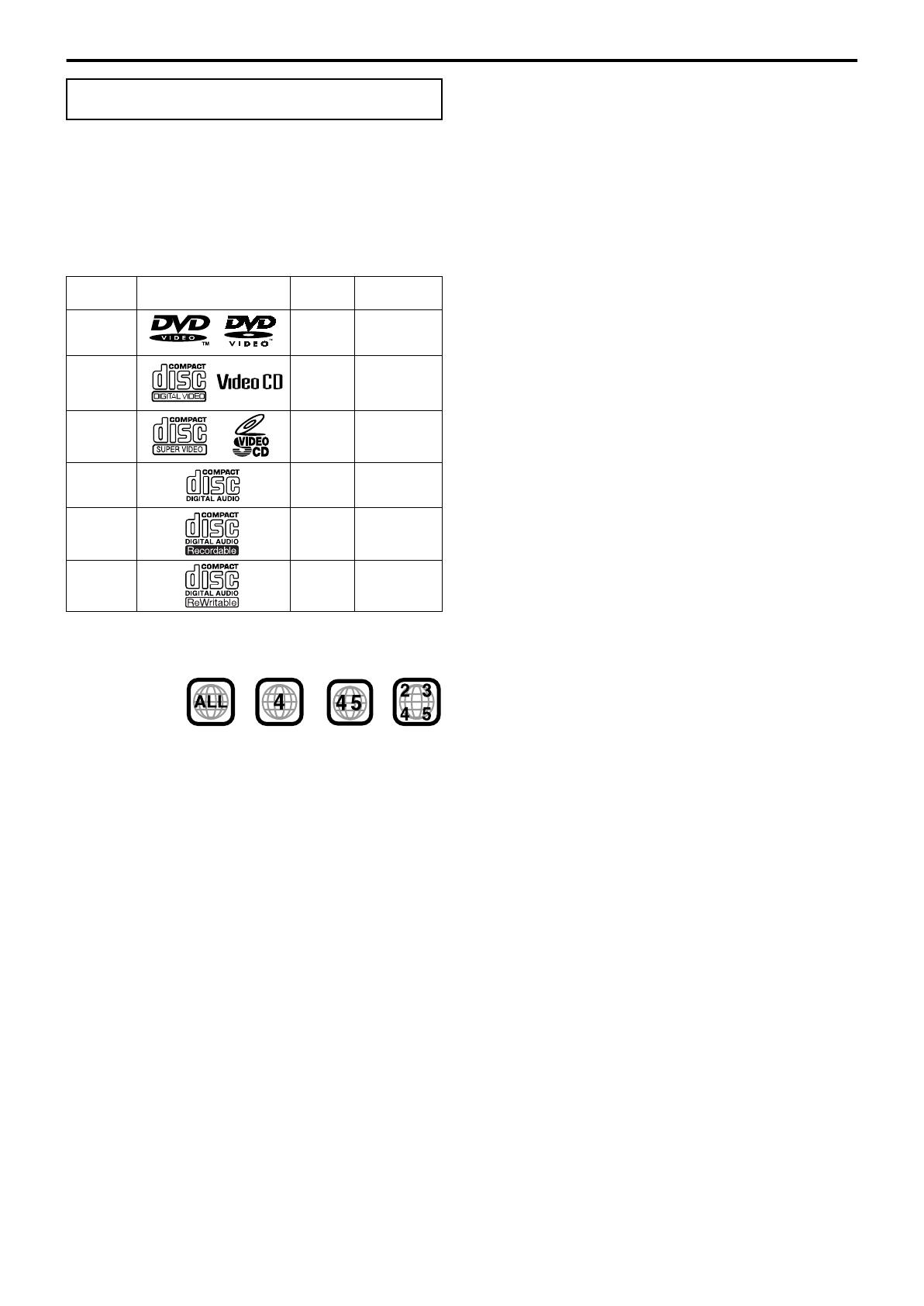
Note on Region Code
DVD players and DVDs have their own Region Code numbers. This
system can only play back DVDs recorded with the color system of
NTSC or PAL whose Region Code number includes “4”.
If a DVD with an improper Region Code number is loaded,
“REGION CODE ERROR!” appears on the TV screen and playback
cannot start.
• The following discs cannot be played back:
DVD Audio, DVD-ROM, DVD-RAM, DVD-RW, CD-ROM,
CD-I (CD-I Ready), Photo CD, etc.
Playing back these discs will generate noise and damage the
speakers.
• On some DVDs, Video CDs or SVCDs, their actual
operation may be different from what is explained in this
manual. This is due to the disc programming and disc
structure, not a malfunction of this system.
Notes on CD-R and CD-RW
• User-edited CD-Rs (Recordable) and CD-RWs (Rewritable) can
be played back only if they are already “finalized”.
• This system can play back CD-Rs or CD-RWs recorded on a
personal computer if they have been recorded in the audio CD
format.
This system can also play back CD-Rs or CD-RWs if MP3 files
or JPEG files are recorded on them.
However, some discs may not be played back because of their
disc characteristics, recording conditions, or damage or stain on
them.
Especially, the configuration and characteristics of an MP3 disc
or a JPEG disc are determined by the writing (encoding) software
and hardware used for recording. Therefore, due to the software
and hardware used, the following symptoms may occur:
•
Some discs may not be played back.
•
Some tracks on an MP3 disc may be skipped or may not be
played back normally.
•
Some files on a JPEG disc may be played back distortedly.
• Before playing back CD-Rs or CD-RWs, read their instructions
or cautions carefully.
• CD-RWs may require a longer readout time. This is caused by
the fact that the reflectance of CD-RWs is lower than that of
regular CDs.
About MP3 discs
MP3 is an abbreviation for Motion Picture Experts Group 1 (or
MPEG-1) Audio Layer 3. MP3 is simply a compressed data file
format. By using MP3 format, one CD-R or CD-RW can contain 10
times as much data as one regular CD.
About JPEG discs
A still-picture data compression system proposed by the Joint
Photographic Expert Group, which features small decrease in
image quality in spite of its high compression ratio.
Notes on MP3/JPEG discs
• MP3/JPEG discs (either CD-R or CD-RW) require a longer
readout time. (It differs due to the complexity of the directory/file
configuration.)
• When making an MP3/JPEG disc, select ISO 9660 Level 1 or
Level 2 for the disc format.
• This system supports “multi-session” discs (up to 5 sessions).
• This system cannot play “packet write” discs.
• The system can only play MP3/JPEG files with the following file
extensions;
MP3: “.MP3”, “.Mp3”, “.mP3” and “.mp3”
JPEG: “.jpg”, “.jpeg”, “.JPG”, “.JPEG” and any uppercase and
lowercase combination (such as “.Jpg”)
• If both MP3 files and JPEG files are recorded on a disc, set the
MP3/JPEG setting in the PICTURE menu to the appropriate
setting for the data to be read (“MP3” or “JPEG”). (
A
pg. 49)
• Some MP3/JPEG discs may not be played back because of their
disc characteristics or recording conditions.
Notes on MP3 discs only
• ID3* tags cannot be shown on the display.
* An MP3 file can contain file information called an “ID3 Tag”
where its album name, performer, track title, etc. are recorded.
There are two versions, ID3v1 (ID3 Tag version 1) and ID3v2
(ID3 Tag version 2).
• We recommend to record each piece of material (song) at a
sample rate of 44.1 kHz and at a data transfer rate of 128 kbps.
• Some tracks on an MP3 disc may be skipped or may not be
played back normally.
Notes on JPEG discs only
• We recommend to record a file at 640 x 480 resolution. (If a file
has been recorded at a resolution of more than 640 x 480, it will
take a longer time to be displayed.)
• This system can only play baseline JPEG files*. Progressive
JPEG files* or lossless JPEG files* cannot be played.
* Baseline JPEG format: Used for digital cameras, web, etc.
Progressive JPEG format:Used for web.
Lossless JPEG format: An old type and rarely used now.
• Some files on a JPEG disc may be played back distortedly.
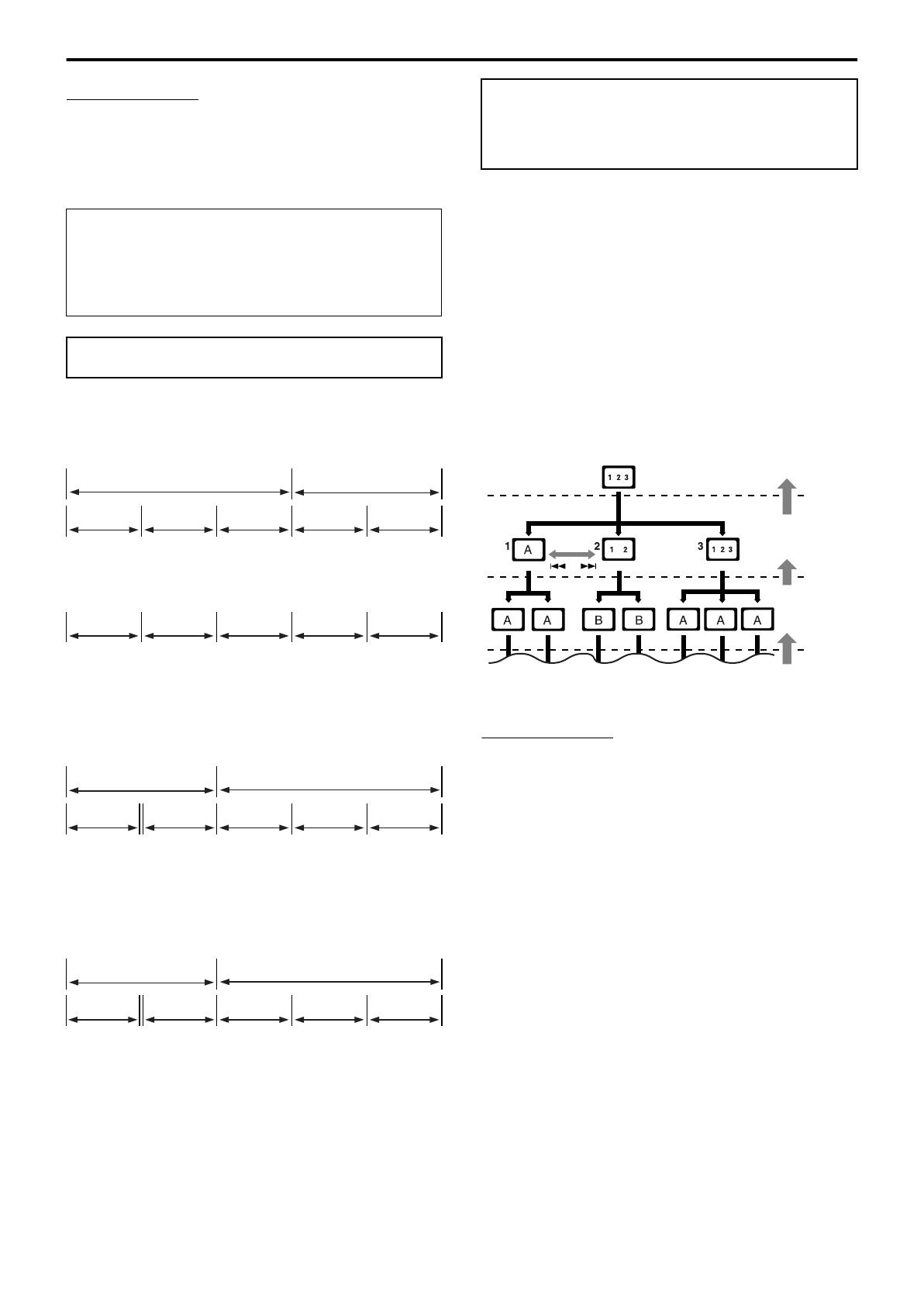
Playable disc types
Disc Type Mark (Logo)
Video
Format
Region Code
Number
*
DVD
NTSC/
PAL
4/ALL
VCD
NTSC/
PAL
—
SVCD
NTSC/
PAL
—
Audio CD — —
CD-R — —
CD-RW — —
Examples:
TH-A85-55[A].book Page 3 Tuesday, May 27, 2003 10:24 AM