
YAMAHA CORPORATION
10-1 Nakazawa-cho, Hamamatsu, Shizuoka 430-8650, Japan
©
2006 All rights reserved.
Printed in Japan
WH86130
This owner’s manual is based on the firmware version 1.2x. The
functions and specifications could be possibly added or changed by a
firmware update.
Visit the PJP website to obtain the latest firmware and manuals.
PJP website:
http://www.yamaha.co.jp/english/product/projectphone/
Ce mode d’emploi se réfère à la version 1.2x du micrologiciel. Des
fonctions et spécifications peuvent être ajoutées ou changées par une
mise à jour du micrologiciel.
Consultez le site PJP pour obtenir les tout derniers micrologiciel et
manuels.
Site PJP:
http://www.yamaha.co.jp/english/product/projectphone/
Dieses Benutzerhandbuch basiert auf der Firmware-Version 1.2x. Die
Funktionen und technischen Daten können möglicherweise durch eine
zukünftige Firmware-Aktualisierung erweitert oder geändert werden.
Besuchen Sie die PJP-Website zum Erhalten der neuesten Firmware
und Anleitungen.
PJP-Website:
http://www.yamaha.co.jp/english/product/projectphone/
As of September, 2006
OWNER’S MANUAL
MODE D’EMPLOI
BEDIENUNGSANLEITUNG
G
IP audio conference system
PJP-100H_UCGB_cv.fm Page 1 Wednesday, August 23, 2006 9:33 AM

IMPORTANT SAFTY INSTRACTIONS
i
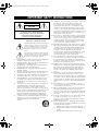
• Explanation of Graphical Symbols
The lightning flash with arrowhead symbol, within an
equilateral triangle, is intended to alert you to the
presence of uninsulated “dangerous voltage” within
the product’s enclosure that may be of sufficient
magnitude to constitute a risk of electric shock to
persons.
The exclamation point within an equilateral triangle
is intended to alert you to the presence of important
operating and maintenance (servicing) instructions in
the literature accompanying the appliance.
1 Read Instructions – All the safety and operating instructions
should be read before the product is operated.
2 Retain Instructions – The safety and operating instructions
should be retained for future reference.
3 Heed Warnings – All warnings on the product and in the
operating instructions should be adhered to.
4 Follow Instructions – All operating and use instructions
should be followed.
5 Cleaning – Unplug this product from the wall outlet before
cleaning. Do not use liquid cleaners or aerosol cleaners.
6 Attachments – Do not use attachments not recommended by
the product manufacturer as they may cause hazards.
7 Water and Moisture – Do not use this product near water –
for example, near a bath tub, wash bowl, kitchen sink, or
laundry tub; in a wet basement; or near a swimming pool;
and the like.
8 Accessories – Do not place this product on an unstable cart,
stand, tripod, bracket, or table. The product may fall,
causing serious injury to a child or adult, and serious
damage to the product. Use only with a cart, stand, tripod,
bracket, or table recommended by the manufacturer, or sold
with the product. Any mounting of the product should
follow the manufacturer’s instructions, and should use a
mounting accessory recommended by the manufacturer.
9 A product and cart combination should be moved with care.
Quick stops, excessive force, and uneven surfaces may
cause the product and cart combination to
overturn.
10 Ventilation – Slots and openings in the cabinet are provided
for ventilation and to ensure reliable operation of the
product and to protect it from overheating, and these
openings must not be blocked or covered. The openings
should never be blocked by placing the product on a bed,
sofa, rug, or other similar surface. This product should not
be placed in a built-in installation such as a bookcase or rack
unless proper ventilation is provided or the manufacturer’s
instructions have been adhered to.
11 Power Sources – This product should be operated only from
the type of power source indicated on the marking label. If
you are not sure of the type of power supply to your home,
consult your product dealer or local power company. For
products intended to operate from battery power, or other
sources, refer to the operating instructions.
12 Grounding or Polarization – This product may be equipped
with a polarized alternating current line plug (a plug having
one blade wider than the other). This plug will fit into the
power outlet only one way. This is a safety feature. If you
are unable to insert the plug fully into the outlet, try
reversing the plug. If the plug should still fail to fit, contact
your electrician to replace your obsolete outlet. Do not
defeat the safety purpose of the polarized plug.
13 Power-Cord Protection – Power-supply cords should be
routed so that they are not likely to be walked on or pinched
by items placed upon or against them, paying particular
attention to cords at plugs, convenience receptacles, and the
point where they exit from the product.
14 Lightning – For added protection for this product during a
lightning storm, or when it is left unattended and unused for
long periods of time, unplug it from the wall outlet and
disconnect the antenna or cable system. This will prevent
damage to the product due to lightning and power-line
surges.
15 Power Lines – An outside antenna system should not be
located in the vicinity of overhead power lines or other
electric light or power circuits, or where it can fall into such
power lines or circuits. When installing an outside antenna
system, extreme care should be taken to keep from touching
such power lines or circuits as contact with them might be
fatal.
16 Overloading – Do not overload wall outlets, extension
cords, or integral convenience receptacles as this can result
in a risk of fire or electric shock.
17 Object and Liquid Entry – Never push objects of any kind
into this product through openings as they may touch
dangerous voltage points or short-out parts that could result
in a fire or electric shock. Never spill liquid of any kind on
the product.
18 Servicing – Do not attempt to service this product yourself
as opening or removing covers may expose you to
dangerous voltage or other hazards. Refer all servicing to
qualified service personnel.
19 Damage Requiring Service – Unplug this product from the
wall outlet and refer servicing to qualified service personnel
under the following conditions:
a) When the power-supply cord or plug is damaged,
b) If liquid has been spilled, or objects have fallen into the
product,
c) If the product has been exposed to rain or water,
IMPORTANT SAFTY INSTRACTIONS
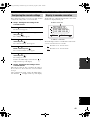
CAUTION
CAUTION: TO REDUCE THE RISK OF
ELECTRIC SHOCK, DO NOT REMOVE
COVER (OR BACK). NO USER-SERVICEABLE
PARTS INSIDE. REFER SERVICING TO
QUALIFIED SERVICE PERSONNEL.
RISK OF ELECTRIC SHOCK
DO NOT OPEN
01EN_00_PJP-100H_UCGB.book Page i Wednesday, August 23, 2006 3:04 PM

IMPORTANT SAFTY INSTRACTIONS
ii
English
d) If the product does not operate normally by following
the operating instructions. Adjust only those controls
that are covered by the operating instructions as an
improper adjustment of other controls may result in
damage and will often require extensive work by a
qualified technician to restore the product to its normal
operation,
e) If the product has been dropped or damaged in any
way, and
f) When the product exhibits a distinct change in
performance - this indicates a need for service.
20 Replacement Parts – When replacement parts are required,
be sure the service technician has used replacement parts
specified by the manufacturer or have the same
characteristics as the original part. Unauthorized
substitutions may result in fire, electric shock, or other
hazards.
21 Safety Check – Upon completion of any service or repairs to
this product, ask the service technician to perform safety
checks to determine that the product is in proper operating
condition.
22 Wall or Ceiling Mounting – The unit should be mounted to a
wall or ceiling only as recommended by the manufacturer.
23 Heat – The product should be situated away from heat
sources such as radiators, heat registers, stoves, or other
products (including amplifiers) that produce heat.
COMPLIANCE INFORMATION STATEMENT
(DECLARATION OF CONFORMITY PROCEDURE)
Responsible Party: Yamaha System Technology Inc.
Address: 100 Century Center Court
san Jose, California 95112
Telephone: (408)467-2300
FAX: (408)437-8791
Type of Equipment: IP Audio Conference System
Model Name: PJP-100H
This device complies with Part 15 of the FCC Rules.
Operation is subject to the following two conditions:
1) this device may not cause harmful interference, and
2) this device must accept any interference received
including interfernce that may cause undesired operation.
See user manual instructions if interference to radio
reception is suspected.
FCC INFORMATION (for US customers)
1 IMPORTANT NOTICE: DO NOT MODIFY THIS
UNIT!
This product, when installed as indicated in the
instructions contained in this manual, meets FCC
requirements. Modifications not expressly approved by
Yamaha may void your authority, granted by the FCC, to
use the product.
2 IMPORTANT: When connecting this product to
accessories and/or another product use only high quality
shielded cables. Cable/s supplied with this product MUST
be used. Follow all installation instructions. Failure to
follow instructions could void your FCC authorization to
use this product in the USA.
3 NOTE: This product has been tested and found to comply
with the requirements listed in FCC Regulations, Part 15
for Class “A” digital devices. Compliance with these
requirements provides a reasonable level of assurance that
your use of this product in a commercial environment will
not result in harmful interference with other electronic
devices. However, operation of this product in a residential
area is likely to cause interference in some form. In this
case you, the user, bear the responsibility of correcting this
condition.
This product generates/uses radio frequencies and, if not
installed and used according to the instructions found in
the users manual, may cause interference harmful to the
operation of other electronic devices.
Compliance with FCC regulations does not guarantee that
interference will not occur in all installations. If this
product is found to be the source of interference, which
can be determined by turning the product “OFF” and
“ON”, please try to eliminate the problem by using one of
the following measures:
Relocate either the product generating the interference or
the device that is being affected by the interference.
Utilize power outlets that are on different branch (circuit
breaker of fuse) circuits or install AC line filter/s.
In the case of radio or TV interference, relocate/reorient
the antenna. If the antenna lead-in is 300 ohm ribbon lead,
change the lead-in to coaxial type cable.
If these corrective measures do not produce satisfactory
results, please contact your local retailer authorized to
distribute this type of product. If you can not locate the
appropriate retailer, please contact Yamaha Electronics
Corp., U.S.A. 6660 Orangethorpe Ave, Buena Park, CA
90620.
The above statements apply ONLY to those products
distributed by Yamaha Corporation of America or its
subsidiaries.
01EN_00_PJP-100H_UCGB.book Page ii Wednesday, August 23, 2006 3:04 PM

iii
1 To assure the finest performance, please read this manual
carefully. Keep it in a safe place for future reference.
2 Install this unit in a well ventilated, cool, dry, clean place with at
least 10 cm on the top, 10 cm on the left and right, and 10 cm at
the back of this unit — away from direct sunlight, heat sources,
vibration, dust, moisture, and/or cold.
3 Locate this unit away from other electrical appliances, motors, or
transformers to avoid humming sounds.
4 Do not expose this unit to sudden temperature changes from cold
to hot, and do not locate this unit in an environment with high
humidity (i.e. a room with a humidifier) to prevent condensation
inside this unit, which may cause an electrical shock, fire,
damage to this unit, and/or personal injury.
5 Avoid installing this unit where foreign object may fall onto this
unit and/or this unit may be exposed to liquid dripping or
splashing. On the top of this unit, do not place:
– Other components, as they may cause damage and/or
discoloration on the surface of this unit.
– Burning objects (i.e. candles), as they may cause fire, damage
to this unit, and/or personal injury.
– Containers with liquid in them, as they may fall and liquid
may cause electrical shock to the user and/or damage to this
unit.
6 Do not cover this unit with a newspaper, tablecloth, curtain, etc.
in order not to obstruct heat radiation. If the temperature inside
this unit rises, it may cause fire, damage to this unit, and/or
personal injury.
7 Do not plug in this unit to a wall outlet until all connections are
complete.
8 Do not operate this unit upside-down. It may overheat, possibly
causing damage.
9 Do not use force on switches, knobs and/or cords.
10 When disconnecting the power cable from the wall outlet, grasp
the plug; do not pull the cable.
11 Do not clean this unit with chemical solvents; this might damage
the finish. Use a clean, dry cloth.
12 Only voltage specified on this unit must be used. Using this unit
with a higher voltage than specified is dangerous and may cause
fire, damage to this unit, and/or personal injury. YAMAHA will
not be held responsible for any damage resulting from use of this
unit with a voltage other than specified.
13 Do not attempt to modify or fix this unit. Contact qualified
YAMAHA service personnel when any service is needed.
The cabinet should never be opened for any reasons.
14 When not planning to use this unit for long periods of time (i.e.
vacation), disconnect the AC power plug from the wall outlet.
15 Be sure to read the “Troubleshooting” section on common
operating errors before concluding that this unit is faulty.
16 Before moving this unit, press and hold (Disconnect) for 3
seconds to set this unit in standby mode, and disconnect the AC
power plug from the wall outlet.
17 Condensation will form when the surrounding temperature
changes suddenly. Disconnect the power cable from the outlet,
then leave the unit alone.
18 When using the unit for a long time, the unit may become warm.
Turn the power off, then leave the unit alone for cooling.
19 Install this unit near the wall outlet and where the AC power plug
can be reached easily.
■ For U.K. customers
If the socket outlets in the home are not suitable for the plug sup-
plied with this appliance, it should be cut off and an appropriate 3
pin plug fitted. For details, refer to the instructions described below.
The plug severed from the mains lead must be destroyed, as a
plug with bared flexible cord is hazardous if engaged in a live
socket outlet.
■ Special Instructions for U.K. Model
CAUTION: READ THIS BEFORE OPERATING YOUR UNIT.
This unit is not disconnected from the AC power source as long
as it is connected to the AC wall outlet, even if this unit itself is
turned off. This state is called the standby mode. In this state,
this unit is designed to consume a very small quantity of power.
FOR CANADIAN CUSTOMERS
To prevent electric shock, match wide blade of plug to wide
slot and fully insert.
This Class A digital apparatus complies with Canadian
ICES-003.
WARNING
TO REDUCE THE RISK OF FIRE OR ELECTRIC SHOCK,
DO NOT EXPOSE THIS UNIT TO RAIN OR MOISTURE.
WARNING
THE POWER SUPPLY CABLE OF THIS UNIT MUST BE
CONNECTED TO THE MAIN SOCKET OUTLET VIA A
PROTECTIVE EARTHING CONNECTION.
WARNING
This is a class A product. In a domestic environment this
product may cause radio interference in which case the user
may be required to take adequate measures.
Note
WARNING-THIS APPARATUS MUST BE
EARTHED.
IMPORTANT
THE WIRES IN THIS MAINS LEAD ARE COLOURED
IN ACCORDANCE WITH THE FOLLOWING CODE:
GREEN-AND-YELLOW:EARTH
BLUE:NEUTRAL
BROWN:LIVE
As the colours of the wires in the mains lead of this appa-
ratus may not correspond with the coloured markings
identifying the terminals in your plug, proceed as follows:
The wire which is coloured GREEN-AND-YELLOW
must be connected to the terminal in the plug which is
marked by the letter E or by the safety earth symbol or
coloured GREEN or GREEN-and-YELLOW.
The wire which is coloured BLUE must be connected to the ter-
minal which is marked with the letter N or coloured BLACK.
The wire which is coloured BROWN must be connected to the
terminal which is marked with the letter L or coloured RED.
01EN_00_PJP-100H_UCGB.book Page iii Wednesday, August 23, 2006 3:04 PM

1
PREPARATIONINTRODUCTION
BASIC CALL
OPERATIONS
CONFIGURATIONS
ADDITIONAL
INFORMATION
English
Features .................................................................. 2
Supplied Accessories ............................................. 3
Controls and Functions......................................... 4
Preparation Procedure.......................................... 8
Step 1: Connecting this unit....................................... 9
Step 2: Registering the network settings of this unit
............................................................................. 10
Step 3: Installing this unit in the conference room
............................................................................. 14
Making a Call....................................................... 15
Calling another unit by specifying an IP address .... 15
Calling another unit using the address book............ 17
Calling another unit in online status ........................ 17
Calling another unit using the call history ............... 18
Answering a Call.................................................. 20
Talking with Multiple Locations ........................ 21
Display and speaker output during multiple
connections .......................................................... 22
Changing the speaker output positions according to
locations............................................................... 23
Configuring Settings ............................................ 24
Configuring settings using the keys on this unit...... 24
Configuring settings using the web menu ............... 25
Setting Menu List ................................................. 26
Managing address book information ....................... 26
Configuring network settings .................................. 26
Configuring sound settings ...................................... 28
Configuring general settings.................................... 31
Storing the call history............................................. 32
Setting the password ................................................ 32
Restoring the factory settings .................................. 32
Editing Address Book .......................................... 33
Registering a new address ....................................... 33
Editing an existing address ...................................... 34
Deleting an address.................................................. 34
Using the SIP Server ............................................ 35
Registering the SIP server information ................... 35
Notes on SIP server operation ................................. 35
Display in SIP server operation ............................... 36
Setting Date and Time ......................................... 37
Managing the Call History .................................. 38
Confirming the System Log Message
of This Unit (syslog) ......................................... 39
Hierarchical Connection of Multiple PJP Units
(Cascade Connection) ...................................... 40
What is cascade connection ? .................................. 40
Configuring the cascade settings ............................. 41
Display in cascade connection................................. 41
Updating the Firmware ....................................... 42
Software Licensing Agreement ............................... 42
Updating the firmware automatically ...................... 43
Updating the firmware manually ............................. 44
Troubleshooting.................................................... 46
Q1: LED indicators do not light up ......................... 46
Q2: Web menu setting is not available .................... 47
Q3: Call is impossible.............................................. 48
Q4: Other problems ................................................. 49
Resetting the Unit ................................................. 50
Obtaining the Setting Information for Support
on this Unit........................................................ 52
Obtaining the setting information............................ 52
Obtaining the audio characteristic information ....... 52
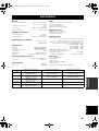
Specifications ........................................................ 53
Notes for Transfer/Disposal of This Unit ........... 54
Contents
INTRODUCTION
PREPARATION
BASIC CALL OPERATIONS
CONFIGURATIONS
ADDITIONAL INFORMATION
01EN_00_PJP-100H_UCGB.book Page 1 Wednesday, August 23, 2006 3:04 PM

FEATURES
2
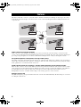
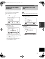
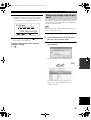
This unit is an IP audio conference system that enables simultaneous talk between multiple locations (up to 4 locations
for the mesh connection and up to 8 locations for the cascade connection) through networks including the Internet and
corporate LAN.
Audio conference through networks
Audio conference can be held by connecting up to 4 locations for the mesh connection and up to 8 locations for the
cascade connection through networks including the Internet and corporate LAN. The audio control employs digital signal
processing so the participants can concentrate on talk without feeling the stress of delay or interruption of words.
Arrayed microphones and speakers for high audio quality
Depending on the using environment, the microphones can control the audio pickup area so that the clear conversation is
assured. Also, the directivity of the speakers is controlled so that clear audio can be transmitted to the participants sitting
in the optimum area even when the volume level is low.
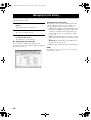
Divide speaker mode for assigning a speaker output position to each talking location
When an audio conference involves more than two locations, the position from which the audio from a location is output
can be assigned per location (Divide function). With previous audio conference systems, the distinction of the talker has
been difficult because the audio from different locations have been mixed. This divide function makes it easy to
distinguish the location of each talker and also improves the feeling of presence of the conference.
Settings from the PC
The [Web Settings Page] incorporated in this unit can be set from a PC without difficulty. The PC settings are convenient
for editing the address book.
Features
Headquarter
Branch B
Branch A Branch C
Internet,
Corporate LAN, etc.
01EN_00_PJP-100H_UCGB.book Page 2 Wednesday, August 23, 2006 3:04 PM

3
Supplied Accessories
INTRODUCTION
English
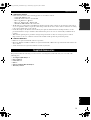
■ About this manual
• In this manual, the names of the following products are described as follows.
– Yamaha PJP-100H: this unit
– Yamaha IP Audio Conference System: PJP
– Microsoft
®
Windows
®
: Windows
– Microsoft
®
Windows XP
®
: Windows XP
– 10BASE-T (100BASE-TX) cable: LAN cable
• The IP addresses, domain names and URL names mentioned in the setting examples are used merely for the purpose
of ease of explanation. When you perform actual settings of this unit, be sure to set the addresses and names according
to the actual configuration of your network.
• Details knowledge on the Internet and network may be required to utilize this unit at its full performance. As the
provided manual does not give detailed technical information, please also refer to commercially available books as
required.
• This manual is printed prior to production. Design and specifications are subject to change in part as a result of
improvements, etc. In case of differences between the manual and the product, the product has priority.
■ About trademarks
• Ethernet is a registered trademark of Xerox Corporation.
• Microsoft, Windows and Microsoft Excel are registered trademarks of Microsoft Corporation in the United States and
other countries.
• Adobe and Acrobat are registered trademarks of Adobe Systems, Inc.
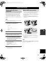
This product includes the following accessories. Before connecting this system, make sure you received all of the
following parts.
• AC adapter (PJP-PS01) x 1
• Power cable x 1
• LAN cable x 1
• Pad x 3
• Owner’s Manual (This manual) x 1
• Warranty card x 1
Supplied Accessories
01EN_00_PJP-100H_UCGB.book Page 3 Wednesday, August 23, 2006 3:04 PM

CONTROLS AND FUNCTIONS
4
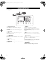
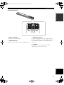
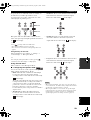
■ Top panel
1 Microphone indicators
A blue LED lights to indicate the audio pick up area.
2 Display
The LCD shows the current status of this unit (page 7).
3 (Cancel)
Press the key to cancel a setting without saving it or to
return to the previous page.
4 / (Up/Down)
Press either key to select a setting item or move the cursor
up or down.
5 (Enter)
Press the key to enter a setting.
6 Numeric keys
Press the keys to enter the figures of the call destination or
IP address.
7 MIC MUTE
Press the key to temporarily defeat (mute) the
microphones of this unit. The LED to the left of the key
lights in red during muting.
Pressing the key again during muting cancels it and turns
the LED off.
8 VOL +/–
Press either key to adjust the speaker volume. Holding
either key increases or decreases the volume continuously.
9 (Disconnect)
Press the key to end a call. Pressing the key when there is
an incoming call can deny its termination.
y
Pressing and holding (Disconnect) for 3 seconds sets this
unit to the standby mode. When this unit is in the standby mode, it
can be turned on again by pressing any key.
0 (Connect)
Press the key when placing a call to the designated
destination or receiving an incoming call.
Controls and Functions
123
456
78
9
0
MIC MUTE VOL
23
1
4567890
01EN_00_PJP-100H_UCGB.book Page 4 Wednesday, August 23, 2006 3:04 PM

5
Controls and Functions
INTRODUCTION
English
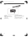
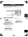
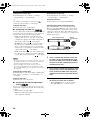
■ Right side panel
1 DC IN 12V terminal
Connect the provided AC adapter.
2 AUDIO IN terminal
Connect to the line output of an audio equipment or PC.
3 AUDIO OUT terminal
Connect to the line input of an audio equipment or PC.
Connecting this terminal to a commercially available IC
recorder makes it possible to record the audio in the
conference.
4 LAN port
Connect a LAN cable for connection to network
equipment such as a PC, router or hub.
42 31
01EN_00_PJP-100H_UCGB.book Page 5 Wednesday, August 23, 2006 3:04 PM

6
Controls and Functions
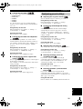
■ Other
1 Serial label
The label carries the following information.
• MODEL No.: Model number of this unit.
• SER.: Serial number for use in management/
distinction of this unit.
2 SERIAL terminal
Reserved for future extension.
3 Arrayed speakers (Bottom panel)
Twelve speakers are arrayed on the bottom panel for use in
output of the audio from the unit(s) communicating with
this unit.
4 Arrayed microphones (Side panels)
Sixteen microphones are arrayed on each side panel for
use in capturing the voices of the talkers.
43
21
01EN_00_PJP-100H_UCGB.book Page 6 Wednesday, August 23, 2006 3:04 PM

7
Controls and Functions
INTRODUCTION
English
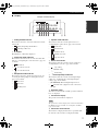
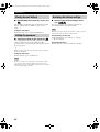
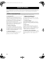
■ Display
1 Calling method indicator
The indicator shows the connection method used for the
current call.
• Call by designating the IP address.
• Call using a SIP server.
2 IP address
The IP address of this unit is displayed.
3 Connection mode indicator
The indicator shows the mode of connection with other
units. See “Configuring the connection mode” (page 27)
for details.
• Mesh mode
• Cascade Server mode
• Cascade Client mode
4 Microphone mode indicator
The indicator shows the current microphone mode. See
“Selecting the audio pickup area (microphone mode)”
(page 28) for details.
• Zone mode
• Spot mode
• Tracking mode
5 Speaker mode indicator
The indicator shows the current speaker mode. See
“Configuring the speaker mode” (page 29) for details.
• Divide mode
• Monaural mode
• Small Area mode
• Medium Area mode
• Large Area mode
6 Room size indicator
The indicator shows the current room size setting. See
“Configuring the room size” (page 30) for details.
• Large setting
• Medium setting
• Small setting
7 External input/output indicator
The indicator shows the current external input/output
setting. See “Configuring the external input/output
setting” (page 30) for details.
• (No indication): External input/output is not set.
• External audio equipment can be connected to
this unit.
8 Operation guide
The names of the currently available operations and their
keys are displayed.
9 Present time display
The present date and time are displayed.
The present time cannot be displayed in an environment in which
the SNTP server is not available. See “Setting Date and Time”
(page 37) for details.
0 Connection error indicator
The indicator is displayed when there is a problem with
the network connection. It is not displayed usually.
2006.05.15 09:48:20
Menu :Address
IP: 192.168.100.200
1 02 83 4 9567
Example of the initial display
Note
01EN_00_PJP-100H_UCGB.book Page 7 Wednesday, August 23, 2006 3:04 PM

PREPARATION PROCEDURE
8
The following preparation steps should be completed before using this unit.
Step 1: (page 9)
Connecting this unit to the network and turning
this unit on
↓
Step 2: (page 10)
Registering the network settings of this unit
The setting method is variable depending on whether or
not the network uses the DHCP server.
↓
Step 3: (page 14)
Installing this unit in the conference room
To configure the settings from a PC
This section describes the preparation method using the
keys on this unit, but the same settings are also available
by accessing the “Web Settings Page” from a PC. See
“Configuring settings using the web menu” (page 25) for
details.
Some functions such as the address book setting cannot be set
using the keys on this unit alone.
To use this unit with a SIP server
The settings have to be performed by accessing the “Web
Settings Page” from a PC. See “Registering the SIP server
information” (page 35) for details.
■ Notes on system connection
Please check the following before proceeding to
preparation.
LAN cable
Prepare a 10BASE-T or 100BASE-TX LAN cable.
Information on the network accommodating
this unit
Obtain or decide the following information prior to
installation of this unit.
• IP address and subnet mask settings of this unit
• IP addresses of the default gateway and DNS server
used by this unit
Notes on the network accommodating this
unit
• When using this unit in the Internet, it is basically
required to obtain a global IP address.
• When using this unit in a corporate LAN, it cannot be
connected to equipment outside the firewall. However,
as calls may become possible by changing the settings
of the router, please consult your network administrator
for details. This unit uses a port number of 5060 (UDP)
for SIP, and 57000 to 57010 (UDP) for RTP/RTCP.
• To prevent the audio from being interrupted, it is
recommended to use a network that can offer enough
transmission bandwidths. See “Specifications”
(page 53) for details.
• If “CODEC Line Adapt” (page 31) is set to “Enable”
and the allocation of transmission bandwidth descends
during a call, this unit selects the optimum encoding
method for the network situations automatically.
Preparation Procedure
Note
01EN_00_PJP-100H_UCGB.book Page 8 Wednesday, August 23, 2006 3:04 PM

Preparation Procedure
9
PREPARATION
English
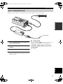
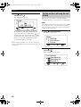
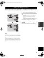
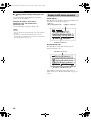
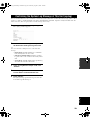
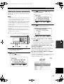
Follow the procedure below to connect this unit to the network, and then connect the AC adapter.
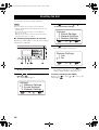
1 Using a LAN cable, connect the LAN port of
this unit to the network.
2 Connect the AC adapter to the DC IN 12V
terminal.
3 Connect the power cable to the AC adapter.
4 Connect the power cable to the AC outlet.
This unit is turned on and the microphone indicators
light up in sequence.
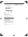
■ Standby mode
Pressing and holding (Disconnect) for 3 seconds sets
this unit to the standby mode. In the standby mode,
“STANDBY” is displayed on the screen of this unit.
To exit the standby mode and switch this
unit on again:
Press any key.
Step 1: Connecting this unit
1
2
3
4
To AC wall outlet
01EN_00_PJP-100H_UCGB.book Page 9 Wednesday, August 23, 2006 3:04 PM

Preparation Procedure
10
Register the IP address and subnet mask of this unit, and the default gateway and DNS server used by it according to the
environment of the LAN in which this unit is accommodated. The operation is different depending on whether or not the
DHCP server is used.
Set a unique IP address to this unit so that it does not overlap with
the IP address of any other equipment already existing in the
LAN.
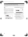
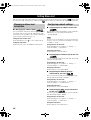
■ Obtaining the IP address automatically
When this unit is used in a network containing a DHCP
server, no setting operation is required since the DHCP
server assigns all of the necessary network information
automatically.
To check if the correct network information
is obtained
Confirm that the IP address of this unit is displayed in the
initial display as shown below.
If the IP address display is “???.???.???.???”
The network information is not obtained correctly.
If the disconnected icon is displayed, this unit is not
connected properly to the network.
– Check if the LAN cable is connected properly.
– Check the condition of the network to which the
LAN cable is connected.
If the icon is not displayed, the network information is
not obtained from the DHCP server.
– There may be a network fault between this unit and
the DHCP server. Consult your system
administrator to solve the trouble with the network.
– If the problem cannot be solved, register the
network information manually (page 11).
Step 2: Registering the network settings of this unit
Note
Menu :Address
IP: 192.168.0.12
Menu :Address
IP: ???.???.???.???
Disconnected icon
01EN_00_PJP-100H_UCGB.book Page 10 Wednesday, August 23, 2006 3:04 PM

Preparation Procedure
11
PREPARATION
English
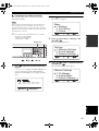
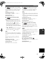
■ Assigning the IP address manually
Follow the procedure below to register the network
information manually.
Before setting the network information, check that this unit is
connected properly to the network. If the disconnected icon
(page 10) is displayed on the top right of the display, check the
LAN cable connection and the condition of the network to which
the LAN cable is connected.
y
The factory settings of the network information are as follows.
– IP address: 192.168.100.200
– Subnet mask: 255.255.255.0
– Default gateway: 0.0.0.0
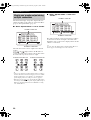
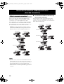
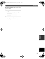
1 Press repeatedly until the initial display
appears.
“???.???.???.???” is displayed when the DHCP server
does not exist in the network, and the IP address
obtained from the DHCP server is displayed when it
exists.
2 Press .
The menu screen appears.
3 Press or to select “1. Settings”, and
then press .
The “Settings” menu appears.
4 Press or to select “1. Network Settings”,
and then press .
The “Network Settings” menu appears.
Note
123
456
78
9
0
MIC MUTE
LAN
VOL
DC IN 12V IN AUDIO OUT
/ /
Numeric keys
Menu :Address
IP: ???.???.???.???
3. Online
2. Call History
1. Settings
Menu
3. General Settings
2. Sound Settings
1. Network Settings
Settings
3. Default Gateway
2. Subnet Mask
1. IP Address
Network Settings
01EN_00_PJP-100H_UCGB.book Page 11 Wednesday, August 23, 2006 3:04 PM

Preparation Procedure
12
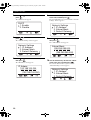
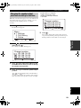
5 Press or to select “5. DHCP”, and then
press .
The “DHCP” menu appears.
6 Press or to select “2. Disable”, and then
press .
The “Network Settings” menu reappears.
7 Press or to select “1. IP Address”, and
then press .
The “IP Address” menu appears.
8 Use the numeric keys to enter the IP address
of this unit, and then press .
The entered IP address is registered and the “Network
Settings” menu reappears.
9 Press or to select “2. Subnet Mask”, and
then press .
The “Subnet Mask” menu appears.
10 Use the numeric keys to enter the subnet
mask of this unit, and then press .
The entered subnet mask is registered and the
“Network Settings” menu reappears.
2. Disable
1. Enable
DHCP
3. Default Gateway
2. Subnet Mask
1. IP Address
Network Settings
(192.168.100.200)
[ ] [#]
192.168.100.200
IP Adress
^
3. Default Gateway
2. Subnet Mask
1. IP Address
Network Settings
(255.255.255.000)
[ ] [#]
255.255.255.000
^
Subnet Mask
3. Default Gateway
2. Subnet Mask
1. IP Address
Network Settings
01EN_00_PJP-100H_UCGB.book Page 12 Wednesday, August 23, 2006 3:04 PM

Preparation Procedure
13
PREPARATION
English
11 Press or to select “3. Default Gateway”,
and then press .
The “Default Gateway” menu appears.
12 Use the numeric keys to enter the “Default
Gateway” of this unit, and then press .
The entered “Default Gateway” is registered and the
“Network Settings” menu reappears.
13 Press or to select “4. DNS Server”, and
then press .
The “DNS Server” menu appears.
14 Use the numeric keys to enter the IP address
of the DNS server referenced by this unit,
and then press .
The entered DNS server IP address is registered and
the “Network Settings” menu reappears.
(000.000.000.000)
[ ] [#]
000.000.000.000
Default Gateway
^
3. Default Gateway
2. Subnet Mask
1. IP Address
Network Settings
(000.000.000.000)
[ ] [#]
000.000.000.000
DNS Server
^
3. Default Gateway
2. Subnet Mask
1. IP Address
Network Settings
01EN_00_PJP-100H_UCGB.book Page 13 Wednesday, August 23, 2006 3:04 PM

Preparation Procedure
14
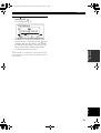
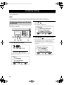
After completing the settings, follow the procedure below to install this unit in the place of conference, such as a
conference room.
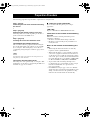
■ About installation environment
The speakers of this unit are attached in the downward orientation on the bottom panel. Place this unit horizontally on a
desktop without placing any object below this unit. In case you cannot place the unit stably because of the shape of the
desk or other reasons, attach the supplied pads (3 pieces) as illustrated.
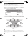
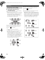
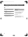
■ Take the positions of the talkers in consideration
To assure the clear conversation by making the most of the effect of arrayed microphones and speakers, place this unit so
that the talkers sit at the area highlighted on the following figure.
The microphones cannot pick up the audio clearly when the talker sits in one of the positions marked “ ” in the figure above.
y
Depending on the using environment, you can configure the setting of the audio pickup area. Refer to “Selecting the audio pickup area
(microphone mode)” (page 28) for details.
Step 3: Installing this unit in the conference room
Note
Display side
Back panel of this unit
1 pad
Concave part
Pad
Rubber cushion
Pad
Attach 1 pad at the center so
that the concave part is
covered.
Attach 2 pads at the corner so that
the rubber cushions are covered.
123
456
78
9
0
MIC MUTE
LAN
VOL
DC IN 12V IN AUDIO OUT
Front of this unit
Front of this unit
Side of
this unit
Side of
this unit
2 pads
01EN_00_PJP-100H_UCGB.book Page 14 Wednesday, August 23, 2006 3:04 PM

Making a Call
15
BASIC CALL
OPERATIONS
English
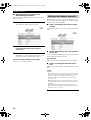
Follow the procedure below to specify an IP address to call another unit. Both PJP units should be turned on and
connected to the network with a LAN cable.
1 Press repeatedly until the initial display
appears.
2 Use the numeric keys to enter the IP address
of the destination unit.
If you make an entry mistake, press (*) or
(#) to move the cursor below the number you want to
correct, and use the numeric keys to enter the correct
figure.
3 Press .
The calling display appears.
Making a Call
Calling another unit by specifying an IP address
123
456
789
0
MIC MUTE
LAN
VOL
DC IN 12V IN AUDIO OUT
MIC MUTE
/
Numeric keys
VOL +/–
Menu :Address
IP: 192.168.0.10
[ ] [#]
000.000.000.000
^
[ ] [#]
000.000.000.000
^
192.168.100.20
:Cancel
01EN_00_PJP-100H_UCGB.book Page 15 Wednesday, August 23, 2006 3:04 PM

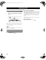
Making a Call
16
The following display appears if the call is connected
by pressing on the destination unit and
conversation becomes available.
• Do not disconnect the LAN cable or power cable during a call.
Doing so may cause malfunction.
• If the call failed, check the following.
– The destination unit is turned on.
– This unit is connected to the network properly.
– Check the call history (page 32) to identify the cause of the
trouble.
– See “Q3: Call is impossible” (page 48).
4
To adjust the speaker volume, press VOL +/ –.
5 To disconnect the call when the conference
is complete, press .
■ To mute the microphone
When you want to talk about a topic that you do not want
to be heard by the other unit(s) involved in the call, press
MIC MUTE. The microphones of this unit are turned off
while the MIC MUTE LED lights up. To cancel muting,
press MIC MUTE again so that the MIC MUTE LED
turns off.
y
The microphone indicators (blue LEDs) do not light up while the
microphones are muted.
■ To make a call involving multiple
locations
See “Talking with Multiple Locations” (page 21).
Notes
Menu :Address
192.168.0.10
192.168.100.20
IP address of this unit
IP address of the destination unit
01EN_00_PJP-100H_UCGB.book Page 16 Wednesday, August 23, 2006 3:04 PM
Page is loading ...
Page is loading ...
Page is loading ...
Page is loading ...
Page is loading ...
Page is loading ...
Page is loading ...
Page is loading ...
Page is loading ...
Page is loading ...
Page is loading ...
Page is loading ...
Page is loading ...
Page is loading ...
Page is loading ...
Page is loading ...
Page is loading ...
Page is loading ...
Page is loading ...
Page is loading ...
Page is loading ...
Page is loading ...
Page is loading ...
Page is loading ...
Page is loading ...
Page is loading ...
Page is loading ...
Page is loading ...
Page is loading ...
Page is loading ...
Page is loading ...
Page is loading ...
Page is loading ...
Page is loading ...
Page is loading ...
Page is loading ...
Page is loading ...
Page is loading ...
Page is loading ...
-
 1
1
-
 2
2
-
 3
3
-
 4
4
-
 5
5
-
 6
6
-
 7
7
-
 8
8
-
 9
9
-
 10
10
-
 11
11
-
 12
12
-
 13
13
-
 14
14
-
 15
15
-
 16
16
-
 17
17
-
 18
18
-
 19
19
-
 20
20
-
 21
21
-
 22
22
-
 23
23
-
 24
24
-
 25
25
-
 26
26
-
 27
27
-
 28
28
-
 29
29
-
 30
30
-
 31
31
-
 32
32
-
 33
33
-
 34
34
-
 35
35
-
 36
36
-
 37
37
-
 38
38
-
 39
39
-
 40
40
-
 41
41
-
 42
42
-
 43
43
-
 44
44
-
 45
45
-
 46
46
-
 47
47
-
 48
48
-
 49
49
-
 50
50
-
 51
51
-
 52
52
-
 53
53
-
 54
54
-
 55
55
-
 56
56
-
 57
57
-
 58
58
-
 59
59


Ask a question and I''ll find the answer in the document
Finding information in a document is now easier with AI
Related papers
-
Yamaha PJP-50R User manual
-
-
-
-
Yamaha PJP-10UR Operating instructions
-
-
Yamaha HTR-3068 User manual
-
Yamaha YMC-700 User manual
-
Yamaha RX-V2700 User manual
-
Other documents
-
LG-Ericsson ACT-50 Quick Install Manual
-
LG PACM5A000 User manual
-
Samsung CLX-8640ND Installation guide
-
-
Vidyo HD-220 User manual
-
Ris JE4AGILITY User manual
-
Panasonic KX-VC300 Operating instructions
-
TANDBERG Codec C60 Administrator's Manual
-
Avaya Equinox User manual
-
Aethra AVC500 Installation guide