5
• Theoutdoorunitrequiresbothpowerandcontrolcircuit
electrical connections. Refer to the wiring diagram /
schematic for identification and location of outdoor unit
field wiring interfaces (Figures 6 - 11, pages 10 - 15).
Make all electrical connections in accordance with all
applicable codes and ordinances.
• Overcurrentprotectionmustbeprovidedatthebranch
circuitdistributionpanelandsizedasshownontheunit
rating label and according to applicable local codes.
See the unit rating plate for minimum circuit ampacity
and maximum overcurrent protection limits.
• Providepowersupplyfortheunitinaccordancewiththe
unit wiring diagram, and the unit rating plate. Connect
the line-voltage leads to the terminals on the contactor
inside the control compartment.
• Useonlycopperwireforthelinevoltagepowersupply
to this unit as listed in Table 1. Use proper code agency
listed conduit and a conduit connector for connecting
the supply wires to the unit. Use of rain tight conduit is
recommended.
• 208/230Voltunitsareshippedfromthefactorywired
for 230 volt operation. For 208V operation, remove the
lead from the transformer terminal marked 240V and
connect it to the terminal marked 208V.
• Optionalequipmentrequiringconnectiontothepower
or control circuits must be wired in strict accordance of
the NEC (ANSI/NFPA 70), applicable local codes, and
the instructions provided with the equipment.
Comfort Alert
TM
Diagnostics Module
(Select Models Only)
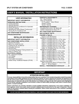
The Comfort Alert
TM
Diagnostics Module (Figure 2) is a
breakthrough innovation for troubleshooting heat pump
and air conditioning system failures. The module installs
easily in the electrical box of the outdoor unit near the
compressorcontactor.Bymonitoringandanalyzingdata
from the Copeland scroll compressor and the thermostat
demand, the module can accurately detect the cause of
electrical and system related failures without any sensors.
A flashing LED indicator communicates the ALERT code
and a diagnostic key is also imprinted on the side of the
module to quickly direct the technician to the root cause
of a problem. NOTE: This module does not provide safety
protection! The Comfort Alert
TM
Diagnostics Module is a
monitoring device and cannot control or shut down other
devices.
24 VAC Power Wiring
The Comfort Alert
TM
module requires a constant nominal
24 VAC power supply. The module cannot be powered by
the C terminal on a defrost board or other control board
without experiencing nuisance alerts. NOTE: The wiring
to the module’s R & C terminals must be routed directly
from the indoor unit or thermostat.
If the constant 24 VAC (R wire) is not present in the outdoor
unit, use one of the spare wires in the thermostat cable to
bring power to the module. Connect the other end of the
spare wire to R at the indoor unit or thermostat.
Figure 2. Comfort Alert
TM
Diagnostics Module
POWER LED
(Green)
TRIP LED
(Red)
ALERT LED
(Yellow)
Diagnostics
Key
Thermostat Demand Wiring
The Comfort Alert
TM
module requires a thermostat demand
signal to operate properly. The thermostat demand
signal input (labeled Y on the module), should always be
connected to the compressor contactor coil. NOTE: When
thecoilisenergized,thedemandsignalinputis24VAC.
Whenthecoilisnotenergized,thedemandsignalinput
should be less than 0.5 VAC.
NOTES:
• Factory installed modules have different thermostat
demand signal wiring. Always follow manufacturer wiring
instructions when replacing the module.
• Afterthethermostatdemandsignalisconnected,verify
that 24 VAC across Y & C when demand is present.
Interpreting the Diagnostic LED’s
When an abnormal system condition occurs, the Comfort
Alert
TM
module displays the appropriate ALERT and/or
TRIP LED will flash a number of times consecutively,
pause and then repeat the process. To identify a Flash
Code number, count the number of consecutive flashes.
Each time the module powers up, the last ALERT Flash
Code that occurred prior to shut down is displayed for
one minute. The module will continue to display the LED
until the condition returns to normal or if 24 VAC power
is removed from the module. See Table 3 (page 16) for
flash code identification or Table 4 (page 17) for module
wiring troubleshooting.
LED Description
• POWERLED(Green):indicatesvoltageispresentat
the power connection of the module.
• ALERT LED (Yellow): communicates an abnormal
system condition through a unique flash code.
NOTE: The ALERT LED will flash consecutively, pause
and then repeat the process. The number of consecutive