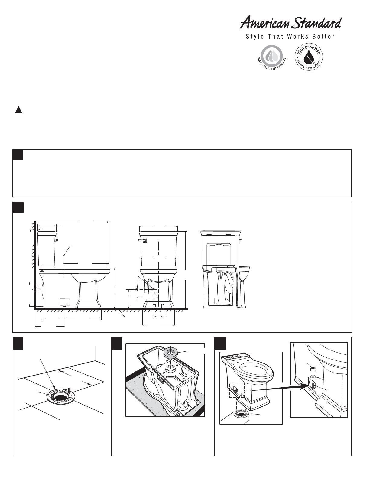
IMPORTANT: Water supply on the wall is required at 2-1/4" or 8" from centerline of the toilet (see rough-in).
First suggested position is hidden behind the toilet. The geometry of the toilet gives space for this installation.
The second suggested position is next to the toilet. Between these two positions, the space for the supply
between wall and toilet is limited to 3-1/2". In this case, check your supply and hose dimensions.
2-1/4"
(57mm)
29-3/4"
(756mm)
7-1/2"
(191mm)
1"
(25mm)
18-1/2"
(470mm)
3-1/2"
(88mm)
2-5/8"
(67mm)
8-1/2"
(217mm)
14-5/8"
(373mm)
12-3/4"
(326mm)
16-1/2"
(419mm)
15-1/4"
(390mm)
31-1/8"
(791mm)
12"
(305mm)
FINISHED
FLOOR
C/L OF SEAT POST
HOLES 5-1/2"
(140mm) CENTERS
SUPPLY
AS
REQUIRED
(position 1 or
position 2)
6"
(152mm)
5-1/2"
(140mm)
14"
(356mm)
8"
(204mm)
BACK VIEW
(for reference)
RECOMMENDED TOOLS AND MATERIALS
Putty Knife Regular Screwdriver Adjustable Wrench Sealant Tape Measure
Hacksaw Wax Ring/Gasket Flexible Supply Tube Closet Bolts Carpenters Level
1 REMOVE OLD TOILET
a. Close toilet supply valve and flush tank completely. Towel or sponge remaining water from tank and bowl.
b. Disconnect and remove supply line. NOTE: If replacing valve, first shut off main water supply!
c. Remove old mounting hardware, remove toilet and plug floor waste opening to prevent escaping sewer gases.
d. Remove closet bolts from flange and clean away old wax, putty, etc. from base area.
NOTE: Mounting surface must be clean and level before new toilet is installed!
SAVE FOR FUTURE USE
2
7301456-100 Rev. C
CAUTION: PRODUCT IS FRAGILE. TO AVOID BREAKAGE AND POSSIBLE INJURY HANDLE WITH CARE!
Product names listed herein are trademarks of AS America, Inc.
© AS America, Inc. 2010
NOTE: Pictures may not exactly define contour of china and components.
Town Square 1.6 gpf / 6 Lpf 2-piece Toilet
Town Square 1.28 gpf / 4.8 Lpf 2-piece Toilet
Model 2817 - Elongated, Right Height
™
with Seat
5
POSITION TOILET ON FLANGE
a. Unplug floor waste opening and install toilet on closet
flange so bolts project through mounting holes.
b. Loosely install retainer washers and nuts. Side of
washers marked "THIS SIDE UP" must face up!
NUT
TAPERED
WASHER
FLANGE
INSTALLATION INSTRUCTIONS
CARE AND MAINTENANCE
Thank you for selecting American Standard - the benchmark of fine quality for over 100 years. To ensure this product is
installed properly, please read these instructions carefully before you begin. (Certain installations may require
professional help.) Also be sure your installation conforms to local codes.
CLOSET
FLANGE
CLOSET
BOLTS
A
INSTALL CLOSET BOLTS
Install closet bolts in flange channel, turn
90
°
, and slide into place 6" (152 mm)
apart and parallel to wall.
!
ROUGHING-IN DIMENSIONS:
NOTE: Distance from wall to closet flange centerline must be as listed below:
IMPORTANT: Water supply on
the wall is required at 2-1/4" or
8" from centerline of the toilet
(see rough-in). First suggested
position is hidden behind the
toilet. The geometry of the toilet
gives space for this installation.
The second suggested position
is next to the toilet. Between
these two positions, the space
for the supply between wall and
toilet is limited to 3-1/2". In this
case, check your supply and
hose dimensions.
WAX RING
INSTALL WAX SEAL
Invert toilet on floor (cushion to prevent
damage), and install wax ring evenly
around waste flange (horn), with
tapered end of ring facing toilet. Apply a
thin bead of sealant around toilet base.
CLOSET
BOLT
43
Certified by
IAPMO R&T
SEALANT


