
Multi-Function
Wireless A/P Router
User’s Guide
Model
CNWR-811P
Wireless Access Point Router
W / Printer Sharing

i
T
ABLE OF
C
ONTENTS
CHAPTER 1 INTRODUCTION..............................................................................................1
CNWR-811P Features .......................................................................................................1
Package Contents...............................................................................................................3
Physical Details ..................................................................................................................4
CHAPTER 2 INSTALLATION ...............................................................................................7
Requirements......................................................................................................................7
Procedure............................................................................................................................7
CHAPTER 3 CONFIGURATION ...........................................................................................9
Overview.............................................................................................................................9
Configuration Program...................................................................................................10
LAN Screen ......................................................................................................................12
WAN Configuration ........................................................................................................14
Wireless Configuration....................................................................................................17
WAN Status......................................................................................................................20
LAN/Device Status...........................................................................................................23
CHAPTER 4 PC CONFIGURATION...................................................................................25
Overview...........................................................................................................................25
TCP/IP Settings................................................................................................................25
Internet Access Configuration........................................................................................28
Printing Setup ..................................................................................................................29
Macintosh Configuration ................................................................................................35
Wireless Configuration....................................................................................................35
CHAPTER 5 DHCP ................................................................................................................36
Overview...........................................................................................................................36
What DHCP Does ............................................................................................................36
Using the CNWR-811P's DHCP Server.........................................................................36
Using another DHCP Server...........................................................................................37
To Configure your PCs to use DHCP.............................................................................37
CHAPTER 6 ROUTING.........................................................................................................38
Overview...........................................................................................................................38
CNWR-811P Configuration............................................................................................38
Router Configuration ......................................................................................................39
Routing Example..............................................................................................................40
CHAPTER 7 OPTIONS..........................................................................................................42
Overview...........................................................................................................................42
Password...........................................................................................................................42
NAT (Network Address Translation).............................................................................43
TFTP .................................................................................................................................43
Remote Management .......................................................................................................43
CHAPTER 8 ADVANCED INTERNET ...............................................................................44
Overview...........................................................................................................................44
Advanced Internet Screen...............................................................................................44
Special Internet Applications..........................................................................................45
Virtual Servers .................................................................................................................47
DMZ..................................................................................................................................51
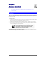
CHAPTER 9 ACCESS CONTROL .......................................................................................53
Overview...........................................................................................................................53
Security Groups ...............................................................................................................54
PCs ....................................................................................................................................56
Filters ................................................................................................................................57

ii
APPENDIX A TROUBLESHOOTING.................................................................................59
Overview...........................................................................................................................59
General Problems.............................................................................................................59
Internet Access .................................................................................................................59
Wireless Access ................................................................................................................60
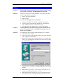
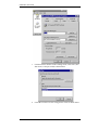
Printing .............................................................................................................................61
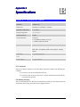
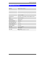
APPENDIX B SPECIFICATIONS ........................................................................................64
CNWR-811P Wireless A/P Router .................................................................................64
PCMCIA Wireless Card..................................................................................................65
Copyright 2001. All Rights Reserved.
Document Version: 1.0
P/N 9560DA0007
All trademarks and trade names are the properties of their respective owners.

1
Chapter 1
Chapter 1Chapter 1
Chapter 1
Introduction
IntroductionIntroduction
Introduction
This Chapter provides an overview of the CNWR-811P's features and capa-
bilities.
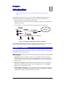
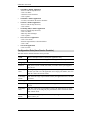
Congratulations on the purchase of your new CNWR-811P Multi-Function Wireless A/P
Router. The CNWR-811P is a multi-function device providing the following services:
• Shared Internet access via an ADSL or Cable modem.
• Wireless LAN Access Point (base station) for equipment compliant with the IEEE802.11b
(DSSS) specifications.
• Network Printer – LAN users can share the printer attached to the CNWR-811P
Interne
iMac
ADSL/Cable Modem
Wireless
Windows
Fast Ethernet
Windows iMac Unix
Internet
iMac
ADSL/Cable Modem
Wireless
Windows
Fast Ethernet
Windows iMac Unix
CNWR-811P
Figure 1: CNWR-811P Multi-function Wireless A/P Router
The CNWR-811P Multi-Function Wireless A/P Router can also be used to connect your local
LAN to a remote LAN or WAN, instead of providing shared Internet Access.
CNWR-811P Features
The CNWR-811P incorporates many advanced features, carefully designed to provide sophisti-
cated functions while being easy to use.
LAN Features
•
Dual LAN ports.
The CNWR-811P has two (2) 10/100BaseTX Ethernet LAN ports.
Normally, the “Hub” port is used to connect the CNWR-811P to your LAN. But if desired,
the “PC” port can be used to connect the CNWR-811P directly to your PC, using a stan-
dard LAN cable.
•
DHCP Server Support.
D
ynamic
H
ost
C
onfiguration
P
rotocol provides a dynamic IP
address to PCs and other devices upon request. The CNWR-811P can act as a
DHCP
Server
for devices on your local LAN.
•
Multi Segment LAN Support.
LANs containing one or more segments are supported,
via the CNWR-811P's built-in static routing table. If NAT (Network Address Translation)
is disabled, the CNWR-811P will function as a static router.
1

CNWR-811P User Guide
2
Internet Access Features
•
Shared Internet Access.
All users on the LAN can access the Internet through the
CNWR-811P, using only a single external IP Address. The local (invalid) IP Addresses are
hidden from external sources. This process is called NAT (Network Address Translation).
•
ADSL & Cable Modem Support.
The CNWR-811P has a 10BaseT Ethernet port for
connecting an ADSL or Cable Modem. All popular ADSL and Cable Modems are sup-
ported.
•
PPPoE Support.
Connect to your ISP using PPPoE (PPP over Ethernet), if your ISP
uses this method.
•
Fixed or Dynamic IP Address.
On the WAN connection, the CNWR-811P supports
both Dynamic IP Address (IP Address is allocated on connection) and Fixed IP Address.
Configuration & Management
•
Easy Setup.
Use your WEB browser from anywhere on the LAN for configuration.
•
Remote Management.
The CNWR-811P can be managed from a workstation anywhere
on the LAN, using a WEB browser.
Wireless Features
•
Standards Compliant.
The CNWR-811P complies with the IEEE802.11b (DSSS)
specifications for Wireless LANs.
•
Security Features.
Support for WEP (Wired Equivalent Privacy) and Access Control is
included.
•
Simple Configuration.
If the default settings are unsuitable, they can be changed
quickly and easily.
Advanced Internet Functions
•
Virtual Servers.
This feature allows Internet users to access Internet servers on your
LAN. The required setup is quick and easy.
•
User-Defined Virtual Servers.
Internet users can access non-standard Internet Servers
on your LAN by using this feature.
•
Special Internet Applications.
Internet applications such as Internet Videoconferenc-
ing, Telephony, Games Servers, and other special-purpose Servers are supported.
•
DMZ.
One (1) PC on your local LAN can be configured to allow unrestricted 2-way
communication with Servers or individual users on the Internet.

Introduction
3
Security Features
•
Configuration Data
. Optional password protection is provided to prevent unauthorized
users from modifying the configuration.
•
Access Control Features
. The LAN Administrator can limit Internet access by individ-
ual workstations.
•
Wireless LAN Security
. WEP (Wired Equivalent Privacy) is supported, as well as
Wireless access control via station address.
•
Firewall Protection.
All incoming data packets are monitored and all incoming server
requests are filtered, thus protecting your network from malicious attacks from external
sources. (This protection is lost if NAT is disabled.)
NAT Firewall Protection
The firewall protection provided by the CNWR-811P is an intrinsic side
effect of NAT (Network Address Translation). All users on the LAN share a
single external IP address. From the external viewpoint, there is no network,
only a single device.
For internal users, the CNWR-811P acts as a “transparent proxy server”,
translating the multiple internal IP addresses into a single external IP ad-
dress.
For external requests, any attempt to connect to local resources are blocked.
The CNWR-811P will not “reverse translate” from a global IP address to a
local IP address.
This type of “natural” firewall provides an impregnable barrier against
malicious attacks.
Package Contents
The following items should be included:
• The CNWR-811P Unit
• Wireless PCMCIA Card
• Power Adapter
• Quick Installation Guide
• CD-ROM containing the on-line manual and Print Port Driver.
If any of the above items are damaged or missing, please contact your dealer as soon as possi-
ble.

CNWR-811P User Guide
4
Physical Details
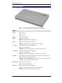
Figure 2: CNWR-811P Multi-Function Wireless A/P Router
LEDs
Power On
- power on
Off
- no power
Status
(Red)
On
- Error condition.
Off
- Normal operation
Blinking
- This LED blinks during start up.
WAN On
- WAN connection is established.
Flashing
- transmitting or receiving data via the WAN port.
LAN: 10 On
- LAN connection is using 10BaseT.
Off
- No LAN connection.
Flashing
- data is being transmitted or received via the LAN port
LAN: 100 On
- LAN connection is using 100BaseT.
Off
- No LAN connection.
Flashing
- data is being transmitted or received via the LAN port
Wireless On
- Wireless connection available; Wireless Access Point is ready for use.
Off
- No Wireless connection available.
Flashing
- Data is transmitted or received via the Wireless access point. This
includes "network traffic" as well as user data.
Print Error On
- Printer error detected.
Off
- No printer error detected.
Print Act On
- Connection to printer established.
Off
- No connection to printer; printer is Off or Off-line.
Flashing
- Data is being transmitted to the printer.

Introduction
5
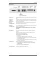
Rear Panel
Figure 3: Rear Panel
Printer Port
Standard parallel printer port. If you wish to share a printer, connect it
here.
WAN port
(10BaseT)
Connect the ADSL or Cable Modem here. If your modem came with
a cable, use the supplied cable. Otherwise, use a standard LAN cable.
DIP switches
Refer to the following table..
PC port
(10/100BaseTX)
If connecting directly to your PC (no Hub) use this port and a stan-
dard LAN cable (RJ45 connectors).
HUB port
(10/100BaseTX)
Use a standard LAN cable (RJ45 connectors) to connect this port to a
10BaseT or 100BaseTX hub.
Use EITHER the PC port OR the Hub port. You can NOT
use both.
Reset Button
When pressed and released, the Wireless A/P Router will reboot
(restart).
This button can also be used to clear ALL data and restore ALL
settings to the factory default values.
To restore the factory default values:
1. Power Off
2. Hold the Reset Button down while you Power On.
3. Keep holding the Reset Button for a few seconds, until the RED
LED has flashed TWICE.
4. Release the Reset Button. The Wireless A/P Router is now using
the factory default values.
PCMCIA slot
Insert the supplied Wireless PCMCIA card into this slot.
•
Ensure the power is OFF before inserting or removing the
PCMCIA Card.
•
Do not use any other PCMCIA Card.
Power port (12V)
Connect the supplied power adapter here.

CNWR-811P User Guide
6
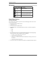
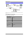
DIP Switches
DIP Switch Setting Description
1=off
2=off
Normal Operation
1=off
2=on
DHCP Server function disabled.
1=on
2=off
Used to restore Default IP Address
and clear Password (See below)
1=on
2=on
Normal Operation.
Restore Default IP Address
and Clear Password
If the CNWR-811P's IP Address or password is lost, the following procedure can be used to
recover from this situation.
1. Turn the power to the CNWR-811P OFF.
2. Set DIP switch 1 ON.
3. Turn the power to the CNWR-811P ON.
4. Operate DIP switch 1 in the following sequence (you have 15 seconds to complete the
sequence):
• OFF
• ON
• OFF
5. The CNWR-811P will now reset, and the Red Status LED flash. The following changes
will have been made. (Other configuration data is unchanged.)
• IP Address set to its default value of 192.168.0.1
• Network Mask set to 255.255.255.0
• DHCP Server is enabled, and will allocate IP Addresses in the range 192.168.0.2 to
192.168.0.51.
• The password cleared (no password).
6. You can now connect to the CNWR-811P and make any configuration changes required.

7
Chapter 2
Chapter 2Chapter 2
Chapter 2
Installation
InstallationInstallation
Installation
This Chapter covers the physical installation of the CNWR-811P.
Requirements
• Ethernet LAN (10/100BaseTX) and the TCP/IP protocol.
• For Internet Access, an ADSL or Cable modem, and an Internet Access account with an
ISP.
• To use the Wireless Access Point, all Wireless devices must be compliant with the
IEEE802.11b specifications.
¼
¼¼
¼
The CNWR-811P's PCMCIA slot is designed to
use ONLY 3.3V PCMCIA Wireless cards.
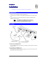
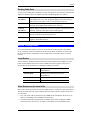
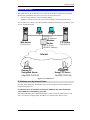
Procedure
Figure 4: Installation Diagram
1. Choose an Installation Site
Select a suitable physical location. Ensure the CNWR-811P and the ADSL/Cable modem
are powered OFF.
2. Insert Wireless PCMCIA card
Ensuring the Wireless PCMCIA card is the right way up, insert it into the slot on the rear.
Push it firmly until it clicks into position.
2

CNWR-811P User Guide
8
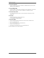
3. Connect LAN Cable
Connect a standard LAN cable from a 10BaseT or 100BaseTX Hub on your LAN to the
“HUB” port on the CNWR-811P.
4. Connect WAN Cable
Connect the ADSL or Cable modem to the WAN port on the CNWR-811P. Use the cable
supplied with your modem. If no cable was supplied, use a standard LAN cable.
5. Connect Printer Cable
Use a standard parallel printer cable to connect your printer to the Printer port on the
CNWR-811P.
6. Power Up
Connect the supplied power adapter and power up.
Use only the power adapter provided.
7. Check the LEDs
• The Status LED should flash, then turn Off. If it stays on, there is a hardware error.
• The Power LED should be ON.
• One (1) of the LAN LEDs (10 or 100) should be ON.
• The Wireless LED should be ON.
• If the printer is On and On-line, the Print Act LED should be ON.
For more information, refer to LEDs in Chapter 1.

9
Chapter 3
Chapter 3Chapter 3
Chapter 3
Configuration
ConfigurationConfiguration
Configuration
This Chapter provides details of the configuration process.
Overview
This chapter describes the procedure for:
• LAN setup
• WAN port configuration for Internet Access
• Wireless access point configuration
PCs on your local LAN may also require configuration. For details, see Chapter 4 - PC Con-
figuration.
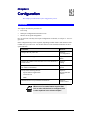
Other configuration may also be required, depending on which features and functions of the
CNWR-811P you wish to use. Use the table below to locate detailed instructions for the re-
quired functions.
To Do this: Refer to:
Configure PCs on your LAN. Chapter 4:
PC Configuration
Learn more about using DHCP on the internal LAN Chapter 5:
DHCP
Configure the CNWR-811P and routers for a LAN which has 1
or more routers.
Chapter 6:
Routing
Set a password for the CNWR-811P, or disable NAT (Net-
work Address Translation).
Chapter 7:
Options
Use any of the following features:
• Special Internet Applications
• Virtual Servers
• DMZ
Chapter 8:
Advanced Internet
Features
Limit Internet Access by individual workstations Chapter 9:
Access Control
Where use of a certain feature requires that
PCs or other LAN devices be configured, this
is also explained in the relevant chapter.
3

CNWR-811P User Guide
10
Configuration Program
The CNWR-811P contains a HTTP server. This enables you to connect to it, and configure it,
using your Web Browser.
Most Browsers should work, provided they support HTML tables and forms.
Preparation
Before attempting to configure the CNWR-811P, please ensure that:
• Your PC can establish a physical connection to the CNWR-811P. The PC and the CNWR-
811P must be directly connected (using the “PC” port on the CNWR-811P) or on the same
LAN segment.
• The CNWR-811P must be installed and powered ON.
• If the CNWR-811P's default IP Address (192.168.0.1) is already used by another device,
the other device must be turned OFF until the CNWR-811P is allocated a new IP Address
during configuration.
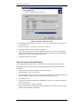
Connecting to the CNWR-811P
To establish a connection from your PC to the device:
1. After installing the CNWR-811P in your LAN, start your PC. If your PC is already run-
ning, restart it.
2. Start your WEB browser.
3. In the Address box, enter "HTTP://" and the IP Address of the CNWR-811P, as in the
following example, which uses the CNWR-811P’s default IP Address:
HTTP://192.168.0.1
4. You should then see the LAN screen.
If you can't connect
If the CNWR-811P does not respond, check the following:
• The CNWR-811P is properly installed, LAN connection is OK, and it is powered
ON.
• Ensure that your PC and the CNWR-811P are on the same network segment. (If
you don't have a router, this must be the case.)
• If your PC is using a fixed IP Address, its IP Address must be within the range
192.168.0.2 to 192.168.0.254 to be compatible with the CNWR-811P's default
IP Address of 192.168.0.1. Also, the Network Mask must be set to
255.255.255.0. See Chapter 4 – PC Configuration for details on checking your
PC’s TCP/IP settings.

Configuration
11
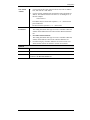
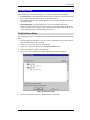
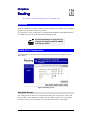
Password
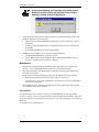
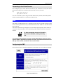
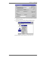
If you have assigned a password to the CNWR-811P you will be prompted for the password, as
shown below.
Figure 5: Password Dialog
• Leave the "User Name" blank.
• Enter the password for this device, if one has been set.
If no password has been set, this dialog will not appear.
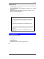
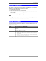
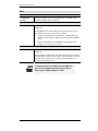
Navigation & Data Input
• Use the menu bar on the left of the screen, and the "Back" button on your Browser, for
navigation.
• Changing to another screen without clicking "Save" does NOT save any changes you may
have made. You must “Save” before changing screens or your data will be ignored.
On each screen, clicking this icon will display
help for that screen.

CNWR-811P User Guide
12
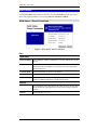
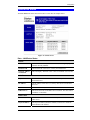
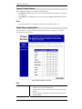
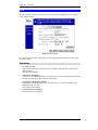
LAN Screen
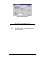
The LAN screen, like the example below, will be displayed when you first connect.
Figure 6: LAN Screen
LAN Configuration.
For most users, the default values for these fields should be satisfactory, and no changes will be
required.
If your LAN contains an existing Router or Routers, refer to Chapter 6 - Routing.
Data – LAN Screen
TCP/IP
IP Address
IP address for the CNWR-811P. Use the default value of 192.168.0.1
unless the address is already in use or your LAN is using a different IP
address range. In the latter case, enter an unused IP Address from within
the range used by your LAN.
Network Mask
The default value 255.255.255.0 is standard for small (class "C") net-
works. For other networks, use the Network Mask for the LAN segment
to which the CNWR-811P is attached. i.e. the same value as the PCs on
that LAN segment.
DHCP Server
Operation
If Enabled, the CNWR-811P will allocate IP Addresses to PCs on your
LAN. The default and recommended value is Enabled.
If you are already using a DHCP Server, this setting must be

Configuration
13
DISABLED, and the existing DHCP server must be re-configured. See
Chapter 5 for further details.
Start IP Ad-
dress
Finish IP
Address
The IP Start Address and IP Finish Address fields set the values used by
the DHCP server.
This range also determines the number of DHCP clients supported.
(Maximum 253.)
DNS (Domain Name Server)
DNS (Domain
Name Server)
IP Addresses
If your ISP uses a “Dynamic IP Address”, then the DNS is also provided
dynamically. Any DNS values entered here will be used instead of the
dynamically-obtained DNS addresses.
If using a “Fixed IP Address”, your ISP should recommend a DNS.
Multiple DNS entries should be entered in the order you want them
accessed. (The first available DNS will be used.)
Routing Table
Routing Table
If your LAN contains an existing Router or Routers, refer to Chapter 6 -
Routing.

CNWR-811P User Guide
14
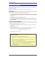
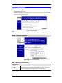
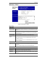
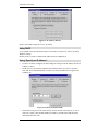
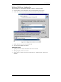
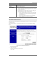
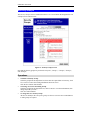
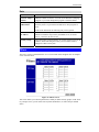
WAN Configuration
To configure the WAN port:
• Select
WAN
from the menu.
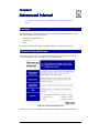
• Select the appropriate connection type (Direct Connection or PPPoE) on the screen below,
then Click the “Configure” button.
Figure 7: WAN Screen
Tip:
If your connection documentation does not refer to PPPoE, select
Direct Connection
.
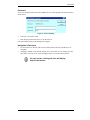
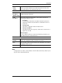
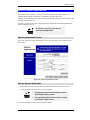
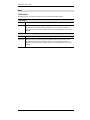
WAN - Direct Connection
Figure 8: WAN - Direct Connection
Data - WAN (Direct Connection)
Device ID
Device (Host)
Name
Normally, there is no need to change the default name, but if your ISP
requests that you use a particular “Hostname”, enter it here. This name
will be provided to, and recorded by, the remote DHCP Server.

Configuration
15
Hardware
(MAC)
Address
Also called Network Adapter Address or Physical Address. Provide this
value to your ISP if requested. If you did not provide this value when
first connected, there is no need to provide it now.
IP Address
Dynamic
IP Address
(DHCP Client)
Leave this enabled if you want your ISP to allocate an IP Address to the
CNWR-811P upon connection.
Fixed
IP Address
Select this if using a fixed IP Address. If this option is selected, the
following data must be entered.
•
IP Address
.
If connecting to an ISP, this is the address allocated by the ISP. If
connecting to another LAN, this must be a valid address on the ex-
ternal LAN.
•
Network Mask
This must be compatible with the IP Address above
•
Gateway IP Address
The address of the router or gateway, either on the external LAN, or
supplied by your ISP.
DNS IP Address
At least 1 DNS IP Address is required, and should be provided by your
ISP. DNS settings are on the LAN screen.
Buttons
Retrieve
Defaults
Get the default Device Name and clear the other items. No changes are
made to the configuration until you click the Save button.
Save
Save any data you have entered on this screen. Remember to save before
changing to another screen.
Cancel
Cancel any data you have entered since the last "Save" operation.
Note:
If using Dynamic IP Address, the IP Address, Network Mask, and Gateway fields may dis-
play the values obtained dynamically.

CNWR-811P User Guide
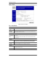
16
WAN - PPPoE
Figure 9: WAN Port - PPPoE
Data – WAN (PPPoE)
Account
Account/User
Name
The name of the Internet account provided by your ISP.
Password
& Verify
Enter the password for the above account. Re-enter the password in the
Verify field, to ensure it is correct.
IP Address
IP Address
provided by
ISP
Normally, this is Dynamic; use this setting if your ISP did not provide an
IP Address.
If your ISP did provide an IP Address, select Fixed and enter the value
they provided.
Options
Idle Time-out
If an connection is inactive for longer than this time period, it will be
terminated. If zero (0), then the connection will never be terminated.
Connect on
Demand
Normally, this should be Enabled. If disabled, you must use the Connect
button on the
Status
screen to establish a connection.
Buttons
Save
Save any data you have entered on this screen. Remember to save before
changing to another screen.
Cancel
Cancel any data you have entered since the last "Save" operation.

Configuration
17
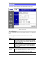
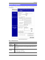
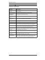
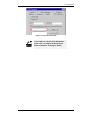
Wireless Configuration
The CNWR-811P settings must match the other Wireless stations. An example
Wireless
screen
is shown below.
Figure 10: Wireless Screen
Data – Wireless Screen
Configuration
Regulatory
Domain
It is illegal to use this device in any location outside of the regulatory
domain.
Station name
This is the same as the Device (Host) Name on the WAN screen. On your
PC, some Wireless status screens may display this name as the Access
Point in use.
SSID
(ESSID)
To communicate, all Wireless stations MUST use the same SSID/ESSID.
The default value is default
Note! The SSID is case sensitive.
Page is loading ...
Page is loading ...
Page is loading ...
Page is loading ...
Page is loading ...
Page is loading ...
Page is loading ...
Page is loading ...
Page is loading ...
Page is loading ...
Page is loading ...
Page is loading ...
Page is loading ...
Page is loading ...
Page is loading ...
Page is loading ...
Page is loading ...
Page is loading ...
Page is loading ...
Page is loading ...
Page is loading ...
Page is loading ...
Page is loading ...
Page is loading ...
Page is loading ...
Page is loading ...
Page is loading ...
Page is loading ...
Page is loading ...
Page is loading ...
Page is loading ...
Page is loading ...
Page is loading ...
Page is loading ...
Page is loading ...
Page is loading ...
Page is loading ...
Page is loading ...
Page is loading ...
Page is loading ...
Page is loading ...
Page is loading ...
Page is loading ...
Page is loading ...
Page is loading ...
Page is loading ...
Page is loading ...
Page is loading ...
-
 1
1
-
 2
2
-
 3
3
-
 4
4
-
 5
5
-
 6
6
-
 7
7
-
 8
8
-
 9
9
-
 10
10
-
 11
11
-
 12
12
-
 13
13
-
 14
14
-
 15
15
-
 16
16
-
 17
17
-
 18
18
-
 19
19
-
 20
20
-
 21
21
-
 22
22
-
 23
23
-
 24
24
-
 25
25
-
 26
26
-
 27
27
-
 28
28
-
 29
29
-
 30
30
-
 31
31
-
 32
32
-
 33
33
-
 34
34
-
 35
35
-
 36
36
-
 37
37
-
 38
38
-
 39
39
-
 40
40
-
 41
41
-
 42
42
-
 43
43
-
 44
44
-
 45
45
-
 46
46
-
 47
47
-
 48
48
-
 49
49
-
 50
50
-
 51
51
-
 52
52
-
 53
53
-
 54
54
-
 55
55
-
 56
56
-
 57
57
-
 58
58
-
 59
59
-
 60
60
-
 61
61
-
 62
62
-
 63
63
-
 64
64
-
 65
65
-
 66
66
-
 67
67
-
 68
68


Ask a question and I''ll find the answer in the document
Finding information in a document is now easier with AI
Related papers
Other documents
-
 Aztech Systems Network Router DSL1015EN User manual
-
MiLAN MIL-W0311 User manual
-
Epson PowerLite 811p Specification
-
Sitecom DC-230 Datasheet
-
Commax CDL-811P/CDL-811R Owner's manual
-
Epson 820P Product information
-
-
-
V7 VPL014-1E Datasheet
-
Epson 730C Product information
