MODEL HV-F202SCL
HV-F202SCL
Specifications
Prod. Code - Order No.
STORED DATE
DESIGNED DATE
CHECKED DATE
A
PPROVED DATE
REV.
21 3 4
TOLERANCE
SCALE
UNIT
F
E
D
C
B
A
SHEET
1
17
DWG.
No.
TITLE
DF022-4PE-
T
1
21 3 4
F
E
D
C
B
A
E400234503
Progressive scan CCD color camera
HV-F202SCL
Specifications
1. General
The HV-F202SCL is an UXGA high precision 3CCD progressive scan color camera, which has
single chip digital processing LSI, a C mount prism, three 1/1.8-inch 2,000,000 pixels square CCDs.
Our original digital image signal processing technology performs the high picture quality signal
processing and the picture compensating functions, beyond the capability of the other conventional
analog cameras.
More ever, high frame rate 30 FPS(s) can be transmitted by miniCameraLink interface, which is of
digital camera standards for FA. The two connector arrangement is considered so that the collision
of cable does not occur at the time of Meidum Configuration connection which enrich the pixel
gradation expression.
2. Outstanding features
(1) High resolution and color fidelity
The 1/1.8-inch 2,000,000 pixels square lattice progressive scan CCD and the dichroic prism for
RGB color achieve a high resolution of UXGA (1600(H) x 1200(V)) picture and good color
reproduction.
(2) Small-sized camera
The new designed camera has small SDR connector for digital output. Therefore, the camera
has the realization of small-sized shape of 55 (W) x 55 (H) x 89 (D) mm.
(3) mini CameraLink interface
CameraLink Version 1.13 support
It is based on the industrial camera interface standard of AIA ( Automated Image
Association) leadership. It is advantageous to the field, where high frame rate is needed
without losing camera performance, since the transmission speed of pixel clock can be
maintained by full screen output.
mini CameraLink
The SDR connector called mini CameraLink is adopted and two connectors are equipped in
a small case. Additionally, when using with L type connection, it is arranged as cable
collision does not occur.
Meidum Configuration connection support
IIt supports Meidum Configuration connection which enables the rich gradation expression
of each color of 10 bit or 12 bit.
-
Mar. 1,2011
(first edition)
H.Kosaka H.Kosaka
SYMBOL DATE DESCRIPTION
(DRAWN) DESIGNED
0
000

SHEET
2
17
DF022-4PE-
S
1
21 3 4
F
E
D
C
B
A
F
E
D
C
B
A
21 3 4
DWG.
No.
E400234503
(4) C mount lens adapter
The de facto industry standard C mount lens adapter allows choosing from a various type of
lenses and optical systems.
(5) Digital processing for various picture quality enhancements
・ Independent six colors masking is the Hitachi innovation for optimizing color balance. The
saturation and the hue of 6 colors (Red, blue, green, cyan, magenta and yellow) are
adjusted independently to deliver the best color in image capture, microscope and other
applications.
・ It is equipped with the in out gradation control function using LUT. Other than normal
gamma 0.45 conversion, the function can set the conversion of in out gradation using look
up table (LUT) as a user option.
(6) Auto shading correction (ASC)
Color shading due to the aberration of C mount lens is automatically compensated (reduced).
(7) Versatile CCD drive functions
・Video frame capture on demand using external trigger signal.
See detailed specifications item 8.
・Long integration mode.
・Auto electronic shutter (AES) mode for stabilized video level.
(8) Versatile imaging functions
・Four application files.
User settings provided for sharpness (detail), masking etc.
・Scene color temperature is detected in dynamic for automatic white balance adjustment.
By varying the detection area in a scene, the whole white balance can be controlled in only the
area. Thus, even if a light source of a different color temperature enters the scene (e.g.,
situation often occurs in a retail showroom suddenly exposed to outdoor lighting when the
entrance door opens), white balance is not severely disturbed.
・Auto exposure (ALC : auto level control)
It can respond the changes in extremely high light by the digital measurement and AGC
(Automatic gain control), AES control using micro computer. In addition, AUTO EXPOSURE
(ALC) setting level and the peak/average of the AUTO EXPOSURE(ALC) characteristics can
be set through menu screen.
・Gain control
AGC(Automatic gain control) and manual gain control are available to select.
・Master black, R/B black, and R/B gain are variable.

SHEET
3
17
DF022-4PE-
S
1
21 3 4
F
E
D
C
B
A
F
E
D
C
B
A
21 3 4
DWG.
No.
E400234503
3. Specifications
(1) Imaging device (sensor type) 1/1.8-inch progressive scan interline CCD (x 3 sensor)
- Indication lens category 1/1.8 inch
Effective pixels (Active area) 1600 (H) x 1200 (V) (x 3 sensor for RGB) : Resolution
Pixel size 4.4 μm square lattice
- scanning area (Pixel area) 7.04mm (H) x 5.28mm (V), Diagonal 8.80mm (1/1.8 inch)
- Readout type, Transfer type progressive scan, Interline transfer
(2) scanning mode full pixel sequential scan
(3) scanning frequency Horizontal : 37.5kHz / Vertical : 29.95Hz / Pixel : 72.0MHz
(4) Optical system 1/1.8-inch F1.8 prism with IR cut filter
Graph is described later.
(5) Lens mount C mount Mount surface projection less than 4.0mm
(6) Flange focal distance 17.526 mm (Air conversion)
(7) Sensitivity 2000 lx, F5.6, light source halogen lamp temp.: 3200K
Shutter : 1/30s, Gain 0dB
(8) Minimum illumination 12 lx, Video Level 50%, Gamma = 0.45
F1.8, Shutter : 1/30s, Gain +12dB
(9) Gamma 0.45 / 1.0 / LUT (Look Up Table : user customizable)
(10) Gain Manual : 0 to 12 dB / AGC : 0 to 12 dB (with limit setting)
(11) White balance Manual / One-push Auto / Continuance Auto
(12) Video output
CaemraLink Version 1.13 standard
Base configuration ( only D.OUT 1 )
Medium configuration ( using D.OUT 1 with D.OUT 2 )
Control : Original
(13) Video output format Base configuration 24bit (R:8bit, G:8bit, B:8bit)
Table is described later.
(14) Quantization level information Maximum data : 255 (8bit), 1023 (10bit), 4095 (12bit)
Video 100% white : 255 (8bit), 1023 (10bit), 4095 (12bit)
Video 0% black : 0, Minimum data : 0
(Lens selection guideline)
Use the lens less than 4.0mm as the projection item from the lens flange surface.
To obtain a good picture image by high resolution and few chromatic aberration, it is
necessary to choose an appropriate high resolution 3CCD type lens.
When using lens other than 1/1.8 type, there may be vignetting or insufficiency of light
around the image or occurrence of flare in the image, in this case combinational lens
selection is necessary.

SHEET
4
17
DF022-4PE-
S
1
21 3 4
F
E
D
C
B
A
F
E
D
C
B
A
21 3 4
DWG.
No.
E400234503
(15) Electric shutter speed OFF / Auto (AES) / Manual (VARIABLE)
Variable shutter mode Exposure time : approx. 1/100,000 to 1/30 second
AES mode
Exposure time : approx. 1/100,000 to 1/29.95(shutter OFF) second
Long time integration mode
Exposure time : approx. 1/30 to 10 seconds in 1 frame steps
(16) Sync system Internal / VD external
(17) Frame on demand mode
Input mode (A) Fixed shutter mode : adjustable for polarity and delay
(B) ONE trigger mode : adjustable for polarity and delay
(C) VD reset mode : negative, frequency Approx. 29.95Hz
Trigger input CameraLink (CC1) or DCIN/SYNC connector
Input level 5Vp-p ± 0.5V
Output strobe signal
VD output : negative, frequency Approx. 29.95Hz
Synchronous output DCIN/SYNC connector
Output level 5Vp-p
(18) Registration Full screen 0.05% (not including lens response)
(19) Vertical contour correction 2H
(20) Sharpness (DTL) Level, WIDTH
(21) Color masking OFF / ON (6 color independent masking)
(22) Paint black Adjustable
(23) Black level Adjustable
(24) Knee Adjustable (Knee point and Knee slope)
(25) Power supply DC+12V ± 1V (input from DC IN / SYNC connector)
(26) Current consumption DC+12V Approx. 600mA (Approx. 7.2W)
(27) Ambient temperature (without dew condensation)
Performance 0 to +40℃ (+32 to +104 F), less than 90 % RH
Operation -10 to +40℃ (+14 to 104 F), less than 90 % RH
Storage -20 to +60℃ (-4 to 140 F), less than 70 % RH
(28) External dimensions 55(W) x 55(H) x 89(D) mm (not including protrusions)
(29) Mass Approx. 350g (without lens)

SHEET
5
17
DF022-4PE-
S
1
21 3 4
F
E
D
C
B
A
F
E
D
C
B
A
21 3 4
DWG.
No.
E400234503
(30) Remote control
(a) Signal system
Control system Start-stop synchronization system
Transmission rate 9600 bps
Data length 8 bits
Start bit 1bit
Stop bit 1bit
Parity None
Bit transfer LSB first
(b) Communications control system
Full control by remote control software, data send/receive by text data transfer to camera
microprocessor (BSC system handshake)
(c) Control items
1. Variable shutter 10 to 1/100,000 second
2. Trigger Mode Fixed shutter, One trigger, VD reset
3. Gain
4. AUTO EXPOSURE
5. White balance
6. Gamma
7. 6 vector independent masking
8. Paint black
9. Sharpness
10. Brightness
11. 24bit / 30bit / 36bit Factory setting: 24bit
12. Trigger pulse polarity Factory setting: POS
13. Trigger input CameraLink (CC1) or DCIN/SYNC connector
Factory setting: CC1
14. Output signal OFF, FLASH OUT and VD OUT
Factory setting: OFF
15. Application files

SHEET
6
17
DF022-4PE-
S
1
21 3 4
F
E
D
C
B
A
F
E
D
C
B
A
21 3 4
DWG.
No.
E400234503
4. Composition
(1) Camera
(2) Lens mount sheet
(3) DCIN/SYNC connector (HR10A-10P-12S)
(4) Installation guide
5. Optional accessories
(1) AC adaptor JC-100 (junction box is included)
(2) Junction box JU-F30
(3) Tripod adaptor TA-F202
(4) 12pin plug HR10A-10P-12S(01)
(5) Camera cable
Molded type Shield type
2 m C-201KSM C-201KSS
5 m C-501KSM C-501KSS
10 m C-102KSM C-102KSS
In the CE Marking region, use the shield type and install clamp filter
(ZCAT2035-0930A: TDK) at both ends of the cable.

SHEET
7
17
DF022-4PE-
S
1
21 3 4
F
E
D
C
B
A
F
E
D
C
B
A
21 3 4
DWG.
No.
E400234503
6. Specification of Digital output connector
(1) DCIN connector
PIN NO. Signal PIN NO. Signal
1 GND (+12V) 7 TRIG-A / VD (H) IN
2 +12V 8 TRIG-B (C) IN
3 GND 9 TRIG-B (H) IN
4 N.C. 10 FLASH / VD OUT
5 N.C. 11 N.C.
6 N.C. 12 TRIG-A / VD (C) IN
Connector (camera side) : SAMWOO SNH-10-12 (RPCB) or equivalent
Plug (matching cable plug) : Hirose HR10A-10P-12S (01) or equivalent
Please do not unplug and insert cable (camera cable) with a power supplied to a camera.
Install clamp filter (ZCAT 2035-0930A: TDK) at both ends (camera and video processor
ends) in the CE marking region.
TRIG-A/VD and TRIG-B are photo coupler input, 8/12/5 pin isisolated with 1/3 pin.
When 8/12/5 pin is connected to GND, please connect to 3 pin.
Note: Please do not input any signal to N.C. pin because machine may break down.
(2) DIGITAL OUT connector
(a) Interrelation between number of DATA bits and number of used connector
Number of Data bits D.OUT1 D.OUT2
1 24bit (R: 8bit G: 8bit B: 8bit) O - O: Use
2 30bit (R: 10bit G: 10bit B: 10bit) O O -: Not use
3 36bit (R: 12bit G: 12bit B: 12bit) O O
D.OUT2
14
26
1
13
D.OUT1

SHEET
8
17
DF022-4PE-
S
1
21 3 4
F
E
D
C
B
A
F
E
D
C
B
A
21 3 4
DWG.
No.
E400234503
(b) Signal connection to DIGITAL OUT connector
Connector 1 (D.OUT1: 24bit / 30bit / 36bit)
Pin No. Signal Pin No. Signal
1 GND 14 GND
2 TXOUT 0 (-) 15 TXOUT 0 (+)
3 TXOUT 1 (-) 16 TXOUT 1 (+)
4 TXOUT 2 (-) 17 TXOUT 2 (+)
5 TXCLKOUT (-) 18 TXCLKOUT (+)
6 TXOUT 3 (-) 19 TXOUT 3 (+)
7 RX (+) [ SERTC (+) ] 20 RX (-) [ SERTC (-) ]
8 TX (-) [ SERTFG (-) ] 21 TX (+) [ SERTFG (+) ]
9 TRIG/VD (-) [ CC1 (-) ] 22 TRIG/VD (+) [ CC1 (+) ]
10 N.U. [ CC2 (+) ] 23 N.U. [ CC2 (-) ]
11 N.U. [ CC3 (-) ] 24 N.U. [ CC3 (+) ]
12 N.U. [ CC4 (+) ] 25 N.U. [ CC4 (-) ]
13 GND 26 GND
Connector 2 (D.OUT2: 30bit / 36bit)
Pin No. Signal Pin No. Signal
1 GND 14 GND
2 TYOUT 0 (-) 15 TYOUT 0 (+)
3 TYOUT 1 (-) 16 TYOUT 1 (+)
4 TYOUT 2 (-) 17 TYOUT 2 (+)
5 TYCLKOUT (-) 18 TYCLKOUT (+)
6 TYOUT 3 (-) 19 TYOUT 3 (+)
7 N.U. 20 N.U.
8 N.U. 21 N.U.
9 N.U. 22 N.U.
10 N.U. 23 N.U.
11 N.U. 24 N.U.
12 N.U. 25 N.U.
13 GND 26 GND
Connector (camera side) Sumitomo 3M 1226-1100-00PL or equivalent
N.U.: Not used
- D.OUT2 is used for Medium configuration.
- The digital out cable should be comprised of a twisted pair of wires having 100 ohm
characteristic impedance and an outer sheath shield type conductor.
- Connect the shield (ground) of the digital out cable to the ground terminal of the video
equipment, frame grabber, etc.
- Install clamp filter (ZCAT2035-0930A: TDK) at both ends (camera and video processor ends) in
the CE marking region.
- TX: Transmit data from camera to PC
- RX: Transmit data from PC to camera
(Note) Please do not unplug and insert cable (digital out cable) with a power supplied to a
camera.

SHEET
9
17
DF022-4PE-
S
1
21 3 4
F
E
D
C
B
A
F
E
D
C
B
A
21 3 4
DWG.
No.
E400234503
7.Video output format (Typical example)
Data length Horizontal Pixels Vertical Pixels FRAME RATE support standard
R:8bit, G:8bit, B:8bit
1600 1200
Approximately
29.95FPS
Base configuration
(using D.OUT1 only)
R:10bit, G:10bit, B:10bit
1600 1200
Approximately
29.95FPS
Medium configuration
R:12bit, G:12bit, B:12bit
1600 1200
Approximately
29.95FPS
Medium configuration
8. Timing chart
8-1. Transmitter LVDS output
(1) DATA TIMING (H)
(2) DATA TIMING (V)
VIDEO
Active Picture
LVAL
1920 clk
1600 clk
110 clk
100 clk
HD
110 clk
Active Picture
VIDEO
FVAL
1252 H
1200 H
12 H
3 H
VD
37 H
1clk = 13.889ns
1H = 1920clk = 26.667
μ
s

SHEET
10
17
DF022-4PE-
S
1
21 3 4
F
E
D
C
B
A
F
E
D
C
B
A
21 3 4
DWG.
No.
E400234503
(3) LVDS SERIAL DATA
(a) Base configuration 24bit
D.OUT 1
N.U.: Not used
0±3ns
Previous Cycle
T
CLK
13.889ns (72.0MHz)
1.41V
1.075V
R7-1 R6-1 N.U. B7 B6 G7 G6 R7 R6
B3-1 B2-1 N.U. FVAL LVAL B5 B4 B3 B2
G2-1 G1-1 B1 B0 G5 G4 G3 G2 G1
R1-1 R0-1 G0 R5 R4 R3 R2 R1 R0
X3
X2
X1
X0
CLKX
Next Cycle
(
VD
)
(
HD
)

SHEET
11
17
DF022-4PE-
S
1
21 3 4
F
E
D
C
B
A
F
E
D
C
B
A
21 3 4
DWG.
No.
E400234503
(b) Medium configuration 36bit / [30bit]
D.OUT 1
N.U.: Not used
D.OUT 2
N.U.: Not used
0±3ns
Previous C
y
cle
T
CLK
13.889ns (72.0MHz)
1.41V
1.075V
R7-1 R6-1 N.U. B7 B6 B11 B10 R7 R6
B3-1 B2-1 N.U. FVAL LVAL B5 B4 B3 B2
R10-1 R9-1 B1 B0 B9 B8 R11 R10 R9
R1-1 R0-1 R8 R5 R4 R3 R2 R1 R0
X3
X2
X1
X0
CLKX
Next C
y
cle
(VD) (HD)
0±3ns
Previous C
y
cle
T
CLK
13.889ns (72.0MHz)
1.41V
1.075V
N.U. N.U. N.U. N.U. N.U. G7 G6 N.U. N.U.
G11-1 G10-1 N.U. FVAL LVAL N.U. N.U. G11 G10
G2-1 G1-1 G9 G8 G5 G4 G3 G2 G1
N.U. N.U. G0 N.U. N.U. N.U. N.U. N.U. N.U.
Y3
Y2
Y1
Y0
CLKY
Next C
y
cle
(VD) (HD)
[
N.U.
]
[
N.U.
]
[
N.U.
]
[
N.U.
]
[
N.U.
]
[
N.U.
]
[
N.U.
]
[
N.U.
]
[
N.U.
]

SHEET
12
17
DF022-4PE-
S
1
21 3 4
F
E
D
C
B
A
F
E
D
C
B
A
21 3 4
DWG.
No.
E400234503
8-2. Normal mode
Shutter time
Shutter time
(
Camera settin
g
Data output
FVAL
1200 H
VD
12H
(* )
37H
3H
1252 H

SHEET
13
17
DF022-4PE-
S
1
21 3 4
F
E
D
C
B
A
F
E
D
C
B
A
21 3 4
DWG.
No.
E400234503
8-3. Fixed shutter mode
When external trigger signal is POSITIVE (high active), after the trigger signal rise, exposure is
start. The exposure time is set by the camera electronic shutter speed. The video output is obtained
immediately after the end of fixed exposure. The strobe signal start/end can be set to shutter time.
Trigger signal input during exposure is disabled.
8-4. ONE Trigger mode
When external trigger signal is POSITIVE (high active), after the trigger signal rise, exposure is start.
At the trigger signal falling edge, the internal VD signal is reset and the video data are transmitted. The
trigger signal width equals the exposure time.
More than 10μs.
Trigger input
(High active)
High
Lo
w
Shutter time
Shutter time
(Camera setting value)
Data
More than 1252H
(*1)
Strobe output
VD
3H
FVAL
37H
Trigger
input
High
Low
Shutter time
Shutter time
(Integration
Data output
More than 1252H
(*1)
Strobe output
VD
3H
FVAL
37H
More than 10μs

SHEET
14
17
DF022-4PE-
S
1
21 3 4
F
E
D
C
B
A
F
E
D
C
B
A
21 3 4
DWG.
No.
E400234503
8-5. VD reset mode
NOTE: If the external VD of cycle which does not match the camera operation mode is input,
shutter time has an error.
High
Low
Data output
VD
3H
FVAL
37H
VD input
(Low active)
VD out
p
ut
3H

SHEET
15
17
DF022-4PE-
S
1
21 3 4
F
E
D
C
B
A
F
E
D
C
B
A
21 3 4
DWG.
No.
E400234503
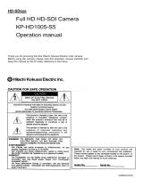
9. Spectral sensitivity characteristics
HV-F202SCL/GV spectrum
0.0
0.1
0.2
0.3
0.4
0.5
0.6
0.7
0.8
0.9
1.0
400 450 500 550 600 650 700
wave length (nm)
Relative sensitivity response
B
G
R
B
GR
Example by the integrated value of the representative sample data of the optical component and
the image sensor in the camera.
10. External view

SHEET
16
17
DF022-4PE-
S
1
21 3 4
F
E
D
C
B
A
F
E
D
C
B
A
21 3 4
DWG.
No.
E400234503
Warranty and service:
1) The guarantee period is two year after the data purchase. However, the defects due to
erroneous use or intentional act are excluded.
2) As the defect after expiration of the guarantee period, where product repair is possible, repair will
be performed at charge.
3) The present Warranty pertains only to the camera unit. Secondary malfunctions attributable to
camera failure as well as expenses incurred by disassembly and reassembly of the related
system, are beyond the scope of this Warranty.
4) Compensation for loss of business, loss or damage to software, database and other contingent
losses are beyond the scope of this Warranty.
5) Hitachi Kokusai Electric Inc. is not liable for the losses caused when the equipment is used in a
system, use for business trades, production process, medical fields, crime prevention
applications, etc.
6) The parts used in the equipment have their respective lives. The lives of such parts will be
shortened under the environments of high temperature or high humidity. When the stable
operation is required for a long time, it is recommended to perform periodical maintenance and
inspection every year or every two years.
Notice:
These specifications are subject to change without prior notice due to product improvement.
Confirm the most recent specifications at time of order.
Hitachi Kokusai Electric certifies this product complies with the standard warranty conditions
of Hitachi Kokusai Electric, and that quality control is implemented to the extent required to
comply with these conditions.

SHEET
17
17
DF022-4PE-
S
1
21 3 4
F
E
D
C
B
A
F
E
D
C
B
A
21 3 4
DWG.
No.
E400234503
Modification history
SIMBLE DATE CORRECTION AND REASONS DESIGNED
/