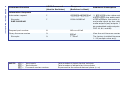
Extron DXP HD 4K Series User manual
- Category
- Video switches
- Type
- User manual

68-2759-50 Rev. B
01 16
DXP HD 4K Series
HDMI Matrix Switchers
Matrix Switchers
Setup Guide

Safety Instructions • English
WARNING: This symbol, , when used on the product, is intended
to alert the user of the presence of uninsulated dangerous voltage
within the product’s enclosure that may present a risk of electric
shock.
ATTENTION: This symbol, , when used on the product, is
intended to alert the user of important operating and maintenance
(servicing) instructions in the literature provided with the
equipment.
For information on safety guidelines, regulatory compliances, EMI/EMF
compatibility, accessibility, and related topics, see the Extron Safety and
Regulatory Compliance Guide, part number 68-290-01, on the Extron
website, www.extron.com.
Instructions de sécurité • Français
AVERTISSEMENT: Ce pictogramme, , lorsqu’il est utilisé sur
le produit, signale à l’utilisateur la présence à l’intérieur du boîtier
du produit d’une tension électrique dangereuse susceptible de
provoquer un choc électrique.
ATTENTION : Ce pictogramme, , lorsqu’il est utilisé sur le produit,
signale à l’utilisateur des instructions d’utilisation ou de maintenance
importantes qui se trouvent dans la documentation fournie avec
le matériel.
Pour en savoir plus sur les règles de sécurité, la conformité à la
réglementation, la compatibilité EMI/EMF, l’accessibilité, et autres sujets
connexes, lisez les informations de sécurité et de conformité Extron, réf.
68-290-01, sur le site Extron, www.extron.com.
Sicherheitsanweisungen • Deutsch
WARNUNG: Dieses Symbol auf dem Produkt soll den Benutzer
darauf aufmerksam machen, dass im Inneren des Gehäuses
dieses Produktes gefährliche Spannungen herrschen, die nicht
isoliert sind und die einen elektrischen Schlag verursachen
können.
VORSICHT: Dieses Symbol auf dem Produkt soll dem Benutzer
in der im Lieferumfang enthaltenen Dokumentation besonders
wichtige Hinweise zur Bedienung und Wartung (Instandhaltung)
geben.
Weitere Informationen über die Sicherheitsrichtlinien,
Produkthandhabung, EMI/EMF-Kompatibilität, Zugänglichkeit und
verwandte Themen finden Sie in den Extron-Richtlinien für Sicherheit
und Handhabung (Artikelnummer 68-290-01) auf der Extron-Website,
www.extron.com.
Instrucciones de seguridad • Español
ADVERTENCIA: Este símbolo, , cuando se utiliza en el
producto, avisa al usuario de la presencia de voltaje peligroso sin
aislar dentro del producto, lo que puede representar un riesgo de
descarga eléctrica.
ATENCIÓN: Este símbolo, , cuando se utiliza en el producto,
avisa al usuario de la presencia de importantes instrucciones
de uso y mantenimiento recogidas en la documentación
proporcionada con el equipo.
Para obtener información sobre directrices de seguridad, cumplimiento
de normativas, compatibilidad electromagnética, accesibilidad y
temas relacionados, consulte la Guía de cumplimiento de normativas
y seguridad de Extron, referencia 68-290-01, en el sitio Web de Extron,
www.extron.com.
Safety Instructions
Инструкция по технике
безопасности • Русский
ПРЕДУПРЕЖДЕНИЕ: Данный символ, , если указан
на продукте, предупреждает пользователя о
наличии неизолированного опасного напряжения
внутри корпуса продукта, которое может привести к
поражению электрическим током.
ВНИМАНИЕ: Данный символ, , если указан на
продукте, предупреждает пользователя о наличии
важных инструкций по эксплуатации и обслуживанию в
руководстве, прилагаемом к данному оборудованию.
Для получения информации о правилах техники
безопасности, соблюдении нормативных требований,
электромагнитной совместимости (ЭМП/ЭДС), возможности
доступа и других вопросах см. руководство по безопасности
и соблюдению нормативных требований Extron на сайте
Extron: www.extron.com, номер по каталогу - 68-290-01.
安全说明 • 简体中文
警告: 产品上的这个标志意在警告用户该产品机壳内有暴露的危险
电 压 ,有 触 电 危 险 。
注意: 产品上的这个标志意在提示用户设备随附的用户手册中有
重要的操作和维护(维修)说明。
关于我们产品的安全指南、遵循的规范、EMI/EMF 的兼容性、无障碍
使用的特性等相关内容,敬请访问 Extron 网站 www.extron.com,参见
Extron 安全规范指南,产品编号 68-290-01。
安全記事 • 繁體中文
警告: 若產品上使用此符號,是為了提醒使用者,產品機殼內存在著
可能會導致觸電之風險的未絕緣危險電壓。
注意 若產品上使用此符號,是為了提醒使用者,設備隨附的用戶手冊
中有重要的操作和維護(維修)説明。
有關安全性指導方針、法規遵守、EMI/EMF 相容性、存取範圍和相關主題的
詳 細 資 訊 ,請 瀏 覽 :Extron 網站:www.extron.com,然後參閱
《Extron 安全性與法規遵守手冊》,準則編號 68-290-01。
安全上のご注意 • 日本語
警告:この記号 が製品上に表示されている場合は、筐体内に絶
縁されて いない高電圧が流れ、感電の危険があることを示し
ていま す。
注意: この記号 が製品上に表示されている場合は、本機の取扱
説明書に 記載されている重要な操作と保守(整備)の指示につい
てユーザーの 注意を喚起するものです。
安全上のご注意、法規厳守、EMI/EMF適合性、その他の関連項目に
つ い て は 、エ ク スト ロ ン の ウ ェ ブ サ イト www.extron.comよ り 『 Extron
Safety and Regulatory Compliance Guide』 (P/N 68-290-01) をご覧く
ださい。
안전 지침 • 한국어
경고: 이 기호 , 가 제품에 사용될 경우, 제품의 인클로저 내에 있는
접지되지 않은 위험한 전류로 인해 사용자가 감전될 위험이 있음을
경고합니다.
주의: 이 기호 , 가 제품에 사용될 경우, 장비와 함께 제공된
책자에 나와 있는 주요 운영 및 유지보수(정비) 지침을 경고합니다.
안전 가이드라인, 규제 준수, EMI/EMF 호환성, 접근성, 그리고 관련
항목에 대한 자세한 내용은 Extron 웹 사이트(www.extron.com)의 Extron
안전 및 규제 준수 안내서, 68-290-01 조항을 참조하십시오.

FCC Class A Notice
This equipment has been tested and found to comply with the limits for a
Class A digital device, pursuant to part15 of the FCC rules. The ClassA
limits provide reasonable protection against harmful interference when
the equipment is operated in a commercial environment. This equipment
generates, uses, and can radiate radio frequency energy and, if not
installed and used in accordance with the instruction manual, may cause
harmful interference to radio communications. Operation of this equipment
in a residential area is likely to cause interference; the user must correct the
interference at his own expense.
NOTE: For more information on safety guidelines, regulatory
compliances, EMI/EMF compatibility, accessibility, and related topics,
see the “Extron Safety and Regulatory Compliance Guide” on the
Extron website.
Copyright
© 2016 Extron Electronics. All rights reserved.
Trademarks
All trademarks mentioned in this guide are the properties of their respective owners.
The following registered trademarks, registered service marks, and trademarks are the
property of RGB Systems, Inc. or Extron Electronics:
Registered Trademarks
(®)
AVTrac, Cable Cubby, CrossPoint, DTP, eBUS, EDID Manager, EDID Minder, Extron,
FlatField, FlexOS, GlobalConfigurator, GlobalViewer, Hideaway, Inline, IPIntercom,
IPLink, KeyMinder, LinkLicense, LockIt, MediaLink, NetPA, PlenumVault,
PoleVault, PowerCage, PURE3, Quantum, SoundField, SpeedMount, SpeedSwitch,
SystemINTEGRATOR, TeamWork, TouchLink, V-Lock, VersaTools, VN-Matrix, VoiceLift,
WallVault, WindoWall, XTP and XTP Systems
Registered Service Mark
(SM)
: S3 Service Support Solutions
Trademarks
(
™
)
AAP, AFL (Accu-RateFrameLock), ADSP(Advanced Digital Sync Processing),
Auto-Image, CableCover, CDRS(ClassDRippleSuppression), DDSP(Digital
Display Sync Processing), DMI (DynamicMotionInterpolation), DriverConfigurator,
DSPConfigurator, DSVP(Digital Sync Validation Processing), eLink, EQIP,
FastBite, FOX, FOXBOX, IP Intercom HelpDesk, MAAP, MicroDigital, ProDSP,
QS-FPC(QuickSwitch Front Panel Controller), Room Agent, Scope-Trigger, ShareLink,
SIS, SimpleInstructionSet, Skew-Free, SpeedNav, Triple-Action Switching, True4K,
Vector, Vector™ 4K, WebShare, XTRA, ZipCaddy, ZipClip

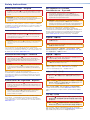
Conventions Used in this Guide
Notifications
CAUTION: Risk of minor personal injury.
ATTENTION : Risque de blessuremineure.
ATTENTION:
• Risk of property damage.
• Risque de dommages matériels.
NOTE: A note draws attention to important information.
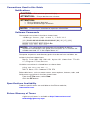
Software Commands
Commands are written in the fonts shown here:
^AR Merge Scene,,Op1 scene 1,1 ^B 51 ^W^C
[01] R 0004 00300 00400 00800 00600 [02] 35 [17] [03]
E X! *X1&* X2)* X2#* X2! CE}
NOTE: For commands and examples of computer or device
responses mentioned in this guide, the character “0” is used for the
number zero and “O” is the capital letter “o.”
Computer responses and directory paths that do not have variables are
written in the font shown here:
Reply from 208.132.180.48: bytes=32 times=2ms TTL=32
C:\Program Files\Extron
Variables are written in slanted form as shown here:
ping xxx.xxx.xxx.xxx —t
SOH R Data STX Command ETB ETX
Selectable items, such as menu names, menu options, buttons, tabs, and
eld names are written in the font shown here:
From the File menu, select New.
Click the OK button.
Specifications Availability
Product specications are available on the Extron website,
www.extron.com.
Extron Glossary of Terms
A glossary of terms is available at http://www.extron.com/
technology/glossary.aspx.

DXP HD 4K Series • Contents v
Contents
Introduction ............................... 1
About this Guide ........................... 1
About the DXP HD 4K Series
Matrix Switchers .......................... 1
Application Diagrams .................... 2
Setup ......................................... 5
Setup Steps................................... 5
Rear Panels and Connections ....... 6
Securing HDMI Cables with the
LockIt HDMI Cable Lacing
Bracket ...................................... 11
Front Panel Cong Port ............... 12
Operation ................................ 13
Front Panel Features ................... 13
Buttons and LEDs ................... 13
DXP HD 4K Front Panels ......... 14
Creating a Tie .............................. 18
Saving or Recalling a Preset ....... 20
Locking and Unlocking the
Front Panel (Executive Mode) .... 22
Selecting Front Panel Lock
Mode 2 or Toggling between
Lock Modes 2 and 0 .............. 22
Selecting Front Panel Lock
Mode 2 or Toggling between
Lock Modes 2 and 1 .............. 24
Viewing Ties ............................... 25
Muting an Output from the
Front Panel ................................. 26
Viewing the Mute
Conguration .......................... 27
Selecting the Remote RS-232
Port Baud Rate .......................... 28
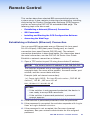
Remote Control ....................... 29
Establishing a Network
(Ethernet) Connection ................ 29
Connection Timeouts .............. 30
Number of Connections .......... 30
Verbose Mode ......................... 30
SIS Commands ........................... 30
Host-to-switcher
Instructions ............................. 30
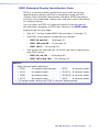
EDID (Extended Display
Identication Data) ................. 31
Symbol Denitions .................. 35
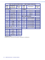
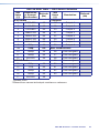
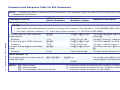
Command and Response Table
for SIS Commands .................... 37
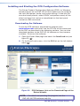
Installing and Starting the PCS
Conguration Software .............. 45
Downloading the Software ...... 45
Starting the Conguration
Program .................................. 47
For More Information ............... 49
Accessing the Web Page ............ 50

DXP HD 4K Series • Contentsvi

DXP HD 4K Series • Introduction 1
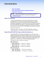
Introduction
• About this Guide
• About the DXP HD 4K Series Matrix Switchers
• Application Diagrams
NOTE: For more information on any subject in this guide,
see the DXP HD 4K Series User Guide, available at
www.extron.com.
About this Guide
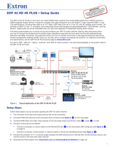
This setup guide allows you to easily and quickly set up and
congure your DXP matrix switcher. Step by step instructions
show you how to connect the hardware and to perform basic
operations using both the front panel controls and selected Simple
Instruction Set (SIS) commands. The guide also shows you how
to load and start up the Product Conguration Software (PCS) and
how to connect to the built-in HTML pages, which you can use to
operate the switcher.
The terms "DXP," "switcher," and "DXP switcher" are used
interchangeably in this guide to refer to all DXP HD 4K models.
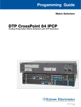
About the DXP HD 4K Series Matrix Switchers
The Extron DXP HD 4K series are digital matrix switchers that
route HDMI signals from multiple sources to any or all of up to 16
HDMI-equipped display devices. All DXP matrix switchers support
resolutions of up to 4K, including 1080p @ 60 Hz Deep Color, and
are HDCP 1.4 compliant, enabling simultaneous distribution of a
single source signal to one or more compliant displays.
The following matrix sizes are available:
DXP 88 Series:
• DXP 44 HD 4K — 4 inputs by 4 outputs
• DXP 84 HD 4K — 8 inputs by 4 outputs
• DXP 88 HD 4K — 8 inputs by 8 outputs
DXP 1616 Series:
• DXP 168 HD 4K — 16 inputs by 8 outputs
• DXP 1616 HD 4K — 16 inputs by 16 outputs

2 DXP HD 4K Series • Introduction
The DXP HD 4K series switchers all provide easy integration
in applications that require reliable HDMI signal routing. They
include several convenience features common to Extron matrix
switchers such as SpeedSwitch, EDID Minder, Key Minder, global
presets, and Ethernet control. In addition, digital audio can be
de-embedded from any input and assigned to digital or analog
stereo outputs.
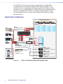
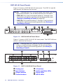
Application Diagrams
QUANTUM CONNECT 408
VIDEO WALL PROCESSOR
DATA
WiFi
1234
WiFi
1234
DBS RECEIVER
DBS RECEIVER
PUSH PUSH
POWERGUIDE MENU RES 480 480p720p 1080i 1080p
DIRECTV HD
SELECT
DIRECTV
PUSH PUSH
POWERGUIDE MENU RES 480 480p720p 1080i 1080p
DIRECTV HD
SELECT
DIRECTV
PUSH PUSH
POWERGUIDE MENU RES 480 480p720p 1080i 1080p
DIRECTV HD
SELECT
DIRECTV
DXP HD 4K SERIES
DIGITAL CROSSPOINT MATRIX SWITCHER
C O N T R O L I/O
CONFIG
1
2
3 4
5
6 7 8
OUTPUTS
AUDIOVIDEO
ESCVIEW
PRESETENTER
1
2
34
5
67
8
9
10
11 12
13
14 15 16
9
10
11 12
13
14 15
16
INPUTS
IPCP PRO 550
OVER
21
43
LIMIT
R
IR
1234567
8
Tx
Rx
Tx
Rx
RTS
CTS
COM
IR/SERIAL
1
3
2
4
RELAYS FLEX
I/O
S
LIMIT
OVER
eBUS
SWITCHED
12 VDC
1000
LINK
ACT
21
56
3
7
4
8
21
56
3
7
4
8
Extron
Help
System
Off
Channel
Display
On
Off
Mute
Screen
Control
Lighting
Control
May 10, 2011 - 2:48 PM
channel
Tuner
Number
Pad
Video Preview
Presets
Bravo
Volume
Mute
Audio
Control
Blu-ray
Security
Camera
PC Laptop DVD AuxTuner
1 2 3
Extron
Help
System
Off
Channel
Display
On
Off
Mute
Screen
Control
Lighting
Control
May 10, 2011 - 2:48 PM
channel
Tuner
Number
Pad
Video Preview
Presets
Bravo
Volume
Mute
Audio
Control
Blu-ray
Security
Camera
PC Laptop DVD AuxTuner
1 2 3
BASSLEVEL TREBLE
MINI POWER AMPLIFIER
MPA 401
Extron
Help
System
Off
Display
Room
Control
Off
Mute
Screen
Lighting
December 15, 2013 - 7:58 AM
Audio
Control
Volume
Mute
Tuner
1 2 3
VCRLaptop PC DVD
Doc
Cam
Tuner
On
Channel
Last
Presets
More
Presets
321
654
987
Enter
0
Extron
Quantum Connect
Scalable Multi-Graphic
Videowall Processor
System
Videowall
Displays
CPUs
Laptops
Operations
Center
Operations Center
HDMI
HDMI
HDMI
HDMI
Ethernet/PoE
Ethernet/PoE
Ethernet/PoE
Ethernet
Ethernet
Audio
Audio
HDMI
HDMI
HDMI HDMI
Trafc Cam
Receivers
Satellite
Receivers
Codec
Extron
DXP HD 4K
4K HDMI Matrix Switcher
with Audio De-Embedding
Extron
FF 220T
Ceiling Speakers
Extron
MPA 401-70V
Power Amplier
Extron
IPCP Pro 550
IP Link Pro
Control Processor
TCP/IP
Network
Extron
TLP Pro 720M
7" Wall Mount
TouchLink Pro Touchpanel
Extron
TLP Pro 720M
7" Wall Mount
TouchLink Pro Touchpanel
Extron
TLP Pro 720T
7" Tabletop
TouchLink Pro Touchpanel
Figure 1. DXP 1616 HD 4K Videowall Application

3DXP HD 4K Series • Introduction
DTP HDMI 230 Rx
OVER DTP
RS-232
IR
TxRx Tx RxG
DTP HDMI 230 Rx
OVER DTP
RS-232
IR
TxRx Tx RxG
DTP HDMI 230 Rx
OVER DTP
RS-232
IR
TxRx Tx RxG
LR
POWER
12V
0.7A MAX
AUDIO
SIG LINK
DTP IN
OUTPUTS
LR
POWER
12V
0.7A MAX
AUDIO
SIG LINK
DTP IN
OUTPUTS
LR
POWER
12V
0.7A MAX
AUDIO
SIG LINK
DTP IN
OUTPUTS
DTP HDMI 230 Tx DTP HDMI 230 Tx DTP HDMI 230 Tx
AUDIO
INPUTS OVER DTP
RS-232
IR
TxRx Tx RxG
POWER
12V
0.7A MAX
SIG LINK
DTP OUT
AUDIO
INPUTS OVER DTP
RS-232
IR
TxRx Tx RxG
POWER
12V
0.7A MAX
SIG LINK
DTP OUT
AUDIO
INPUTS OVER DTP
RS-232
IR
TxRx Tx RxG
POWER
12V
0.7A MAX
SIG LINK
DTP OUT
POWER
12V
1.5A MAX
CLASS 2 WIRING
L
(SUMMED)
(SUMMED)
R
VCG
MPA 401-70V
R
L
10V 50mA
REMOTE
70 V OUTPUT
INPUTS
POWER
12V
1.5A MAX
CLASS 2 WIRING
L
(SUMMED)
(SUMMED)
R
VCG
MPA 401-70V
R
L
10V 50mA
REMOTE
70 V OUTPUT
INPUTS
POWER
12V
1.5A MAX
CLASS 2 WIRING
L
(SUMMED)
(SUMMED)
R
VCG
MPA 401-70V
R
L
10V 50mA
REMOTE
70 V OUTPUT
INPUTS
eBUS
FLEX I/O
RELAYSIR/SERIALCOM12 VDC
LAN
+V
TxRx GTxRxGTxRxGTxRxG SGSG SG SGRTSCTS
+-+-
+-+-
-S G
PWR OUT = 12W
+S
SGSG SGSGTxRx GTxRxGTxRxGTxRxGRTSCTS
1 2 3 4 G
1234
5678
1
1234
5678
2 3 7
4 5 6 8
1 2
3
100-240V ~ 50-60Hz
5A MAX
SWITCHED 12 VDC
40W MAX TOTAL
4
IPCP PRO 550
100-240V --A MAX
50-60 Hz
USB STORAGE
RESET
LAN
1
3
B-Y
R-YVID
/Y
4
HDMI
HDMI
HDMI
AUDIO
LR
LR
HDMI
LOOPOUT
2
INPUTS-CH A
INPUTS-CH B
OUTPUTS
SMP 351
1234G
DIGITAL I/O
Tx Rx
RS-232
G
REMOTE
AUDIOLR
AUDIOLR
MOUSE /
KEYBOARD
1
2
100-240V --A MAX
50-60 Hz
USB STORAGE
RESET
LAN
1
3
B-Y
R-YVID
/Y
4
HDMI
HDMI
HDMI
AUDIO
LR
LR
HDMI
LOOPOUT
2
INPUTS-CH A
INPUTS-CH B
OUTPUTS
SMP 351
1234G
DIGITAL I/O
Tx Rx
RS-232
G
REMOTE
AUDIOLR
AUDIOLR
MOUSE /
KEYBOARD
1
2
100-240V --A MAX
50-60 Hz
USB STORAGE
RESET
LAN
1
3
B-Y
R-YVID
/Y
4
HDMI
HDMI
HDMI
AUDIO
LR
LR
HDMI
LOOPOUT
2
INPUTS-CH A
INPUTS-CH B
OUTPUTS
SMP 351
1234G
DIGITAL I/O
Tx Rx
RS-232
G
REMOTE
AUDIOLR
AUDIOLR
MOUSE /
KEYBOARD
1
2
100-240V ~ 1.1A MAX
50-60 Hz
DXP 1616 HD 4K
INPUTS
INPUTS
OUTPUTS
OUTPUTS
AUDIO OUTPUTS
REMOTELAN
1
5
9
13
2
6
10
14
3
7
11
15
4
8
12
16
1
1
2
3
4
5
9
13
2
6
10
14
3
7
11
15
4
8
12
16
Tx Rx G
L
S/PDIF
RESET
S/PDIF
R
L
R
!
1
@
2
#
3
$
4
%
5
^
6
&
7
*
8
(
9
)
0
_
-
+
=
|
\
}
]
{
[
~
`
QWERTYUIOP
“
‘
:
;
<
,
>
.
?
/
ASDFGHJ
ZXCVBNM
KL
control
shift
caps lock
tab
esc
F1 F2 F3 F4 F5 F6 F7 F8 F9 F10F11 F12F13 F14F15 F16F17 F18F19
alt
optioncommand
delete
fn home clear
enter
=/
*
8
-
5
2
7
0.
4
1
+
9
6
3
page
up
page
down
enddelete
commandoption control
shift
return
!
1
@
2
#
3
$
4
%
5
^
6
&
7
*
8
(
9
)
0
_
-
+
=
|
\
}
]
{
[
~
`
QWERTYUIOP
“
‘
:
;
<
,
>
.
?
/
ASDFGHJ
ZXCVBNM
KL
control
shift
caps lock
tab
esc
F1 F2 F3 F4 F5 F6 F7 F8 F9 F10F11 F12F13 F14F15 F16F17 F18F19
alt
optioncommand
delete
fn home clear
enter
=/
*
8
-
5
2
7
0.
4
1
+
9
6
3
page
up
page
down
enddelete
command option control
shift
return
!
1
@
2
#
3
$
4
%
5
^
6
&
7
*
8
(
9
)
0
_
-
+
=
|
\
}
]
{
[
~
`
QWERTYUIOP
“
‘
:
;
<
,
>
.
?
/
ASDFGHJ
ZXCVBNM
KL
control
shift
caps lock
tab
esc
F1 F2 F3 F4 F5 F6 F7 F8 F9 F10F11 F12F13 F14F15 F16F17 F18F19
alt
optioncommand
delete
fn home clear
enter
=/
*
8
-
5
2
7
0.
4
1
+
9
6
3
page
up
page
down
enddelete
commandoption control
shift
return
Extron
Help
System
Off
Display
Room
Control
Off
Mute
Screen
Lighting
December 15, 2013 - 7:58 AM
Audio
Control
Volume
Mute
Tuner
1 2 3
VCRLaptop PC DVD
Doc
Cam
Tuner
On
Channel
Last
Presets
More
Presets
321
654
987
Enter
0
Extron
Help
System
Off
Display
Room
Control
Off
Mute
Screen
Lighting
December 15, 2013 - 7:58 AM
Audio
Control
Volume
Mute
Tuner
1 2 3
VCRLaptop PC DVD
Doc
Cam
Tuner
On
Channel
Last
Presets
More
Presets
321
654
987
Enter
0
Extron
Help
System
Off
Display
Room
Control
Off
Mute
Screen
Lighting
December 15, 2013 - 7:58 AM
Audio
Control
Volume
Mute
Tuner
1 2 3
VCRLaptop PC DVD
Doc
Cam
Tuner
On
Channel
Last
Presets
More
Presets
321
654
987
Enter
0
WiFi
1234
WiFi
1234
WiFi
1234
STANDBY/ON
PQLS HDMI OPEN/CLOSEFL OFF
USB
STANDBY/ON
PQLS HDMI OPEN/CLOSEFL OFF
USB
STANDBY/ON
PQLS HDMI OPEN/CLOSEFL OFF
USB
PUSH PUSH
POWER GUIDE MENU RES480 480p 720p 1080i 1080p
DIRECTV HD
SELECT
DIRECTV
PUSH PUSH
POWER GUIDE MENU RES480 480p 720p 1080i 1080p
DIRECTV HD
SELECT
DIRECTV
PUSH PUSH
POWER GUIDE MENU RES480 480p 720p1080i 1080p
DIRECTV HD
SELECT
DIRECTV
Extron
DTP HDMI
4K 230 Tx
Transmitter
Extron
DTP HDMI
4K 230 Rx
Receiver
CATx Cable
up to 230' (70 m)
Wireless Keyboard
and Mouse
Projector
HDMI
RS-232
Extron
TLP Pro 720M
7" Wall Mount
TouchLink Pro
Extron
FF 220T
Flat Field
Ceiling
Speakers
Extron
MPA 401-70V
Power
Amplier
Extron
DTP HDMI
4K 230 Tx
Transmitter
Extron
DTP HDMI
4K 230 Rx
Receiver
CATx Cable
up to 230' (70 m)
Wireless Keyboard
and Mouse
Projector
HDMI
RS-232
Extron
TLP Pro 720M
7" Wall Mount
TouchLink Pro
Extron
FF 220T
Flat Field
Ceiling
Speakers
Extron
MPA 401-70V
Power
Amplier
Extron
DTP HDMI
4K 230 Tx
Transmitter
Extron
DTP HDMI
4K 230 Rx
Receiver
CATx Cable
up to 230' (70 m)
Wireless Keyboard
and Mouse
Projector
HDMI
HDMI
HDMI
HDMI
HDMI
HDMI HDMI
Audio
Audio
Audio
Audio
HDMI
Audio
HDMIHDMI
Audio
RS-232
Extron
TLP Pro 720M
7" Wall Mount
TouchLink Pro
Extron
FF 220T
Flat Field
Ceiling
Speakers
Extron
MPA 401-70V
Power
Amplier
TCP/IP
Network
Extron
IPCP Pro 550
IP Link Pro Control Processor
Extron
SMP 351
Streaming Media Processors
Blu-ray Players
Satellite Receivers
CPUs
Extron
DXP HD 4K
4K HDMI
Matrix Switcher
with Audio
De-embedding
Room 1
Room 2
Room 3
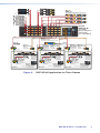
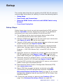
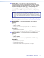
Figure 2. DXP HD 4K Application for Three Rooms

4 DXP HD 4K Series • Introduction

DXP HD 4K Series • Setup 5
Setup
This section describes the rear panels of the DXP HD 4K switchers
and provides instructions for cabling. It covers the following topics:
• Setup Steps
• Rear Panels and Connections
• Securing HDMI Cables with the LockIt HDMI Cable Lacing
Bracket
• Front Panel Config Port
Setup Steps
Follow these steps to set up and start operating the DXP switcher.
See the Operation section, beginning on page 13, for additional
procedures you may want to perform to set up the DXP.
1. Turn off power to the input and output devices that will be
connected and disconnect their power cords.
2. Connect HDMI input devices to the rear panel input connectors
(see figures 3 and 4,
A
, on the next page).
3. Connect HDMI audio and video output devices to the rear panel
output connectors (see figures 3 and 4,
B
).
4. (Optional, DXP 1616 Series only) Change any required button
labels (see "Making Labels Using the Button-Label Generator
Program — DXP 1616 Series Only" in the DXP HD 4K User
Guide).
5. If desired, connect a computer or control system to the Remote
RS-232 control port (see figures 3 and 4,
E
) or to the front
panel USB Cong port (see figures 10 and 11,
E
, on page 14).
6. If desired, connect a network switch, a control system, or a
computer to the RJ-45 LAN port (see figures 3 and 4,
F
).
7. Plug the DXP switcher into a grounded AC source, and connect
power to the input and output devices.
8. Download the Extron Product Conguration Software (PCS)
from www.extron.com.
9. Select EDID les to apply to inputs as desired, using SIS
commands or the PCS conguration software. See EDID
(Extended Display Identification Data) on page 31, or see the
conguration program help le and the DXP HD 4K Series User
Guide for details.
10. Create ties and presets as desired (see Creating a Tie on
page 18 or Saving or Recalling a Preset on page 20).

6 DXP HD 4K Series • Setup
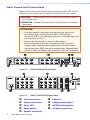
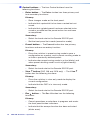
Rear Panels and Connections
Most of the connectors are on the rear panels of the DXP HD 4K.
Figures 3 and 4 show the rear panels of two of the ve models.
CAUTION: Remove power from the system before making
any connections.
ATTENTION : Couper l’alimentation avant de faire l’installation
électrique.
ATTENTION:
• Use electrostatic discharge precautions (be electrically
grounded) when making connections. Electrostatic
discharge (ESD) can damage equipment, although you may
not feel, see, or hear it.
• Prenez des précautions contre les décharges
électrostatiques (soyez électriquement relié à la terre)
lorsque vous effectuez des connexions. Les décharges
électrostatiques (ESD) peuvent endommager l’équipement,
même si vous ne pouvez pas le sentir, le voir ou l’entendre.
Tx Rx G
RESET
REMOTE
DXP 88 HD 4K
SPDIF
L
R
1
2
AUDIO OUTPUTS
OUTPUTS
1
5
2
6
3
7
4
8
INPUTS
1
5
2
6
3
7
4
8
100-240V ~ 1.0A MAX
50-60 Hz
CC
B
B
AA
FF
E
E
DD
II
H
H
G
G
LAN
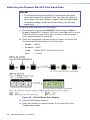
Figure 3. DXP 88 HD 4K Rear Panel
DXP 1616 HD 4K
I NPUTS
OUTPUTS
REMOTE
LAN
100-240V ~ 1.1A MAX
50-60 Hz
1
5
9
13
2
6
10
14
3
7
11
15
4
8
12
16
1
1
2
3
4
5
9
13
2
6
10
14
3
7
11
15
4
8
12
16
Tx Rx G
L
S/PDIF
RESET
S/PDIF
R
L
R
CC
B
B
AA
FF
E
E
D
D
I
IH
H
G
G
A UDIO OUTPUTS
Figure 4. DXP 1616 HD 4K Rear Panel
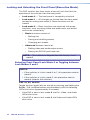
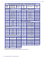
A
Input connectors
F
LAN port
B
Output connectors
G
Analog audio outputs
C
Reset LED
H
S/PDIF audio outputs
D
Reset button
I
AC power connector
E
Remote connector

7DXP HD 4K Series • Setup
NOTE: Figures 3 and 4 on the previous page show
the DXP 88 HD 4K, with 8 inputs and 8 outputs, and
DXP 1616 HD 4K, with 16 inputs and 16 outputs.
• The rear panels of the DXP 44, 84, and 88 are identical
except for the number of inputs and outputs.
• The rear panels of the DXP 168 and 1616 are identical
except for the number of outputs (both have 16 inputs).
A
Input connectors — Connect HDMI source devices to
these female 19-pin type A HDMI input connectors for
video input.
LockIt™ cable lacing brackets, one for each HDMI input and
output connector, are provided with the DXP HD 4K. These
brackets can be used to secure the HDMI cables to the
DXP connectors to reduce stress on the HDMI connectors
and prevent signal loss due to loose cable connections (see
Securing HDMI Cables with the LockIt HDMI Cable Lacing
Bracket on page 11).
B
Output connectors — Connect HDMI output devices
to these female 19-pin type A HDMI output connectors
for buffered video output (see Securing HDMI Cables
with the LockIt HDMI Cable Lacing Bracket).
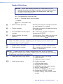
C
Reset LED — While you are holding the Reset
button, this green LED blinks every 3 seconds to
indicate the level of reset that will occur if the button
is released at that point (see
D
Reset button).
D
Reset button — This recessed button initiates four
levels (modes) of reset. Use a pointed object such as a
small screwdriver to press and hold the Reset button.
• Factory firmware reset (mode 1) — Hold the Reset
button while powering up the switcher to restore the DXP to
the factory rmware for a single power cycle.
NOTE: This type of reset maintains all the current user
settings, such as audio adjustments, IP settings, and
the configuration.
• Event reset (mode 3) — This mode is not supported. If
you select it by accident, the Reset LED blinks three times
and no reset occurs.
• IP settings reset (mode 4) — While the DXP is running,
press and hold the Reset button until the LED blinks twice
(approximately 6 seconds). Release the button and press it
again momentarily to reset the switcher IP functions.
NOTE: An IP settings reset does not replace any user
installed firmware.
1
1
RESET
DXP 88 Series
RESET
DXP 1616
Series

8 DXP HD 4K Series • Setup
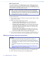
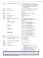
• Absolute reset (mode 5) — While the DXP is running,
press and hold the Reset button until the LED blinks three
times (approximately 9 seconds). Release the button and
press it again momentarily to restore the switcher to the
default factory conditions.
For more details on these reset modes, see the
DXP HD 4K User Guide, available at www.extron.com.
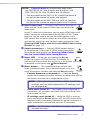
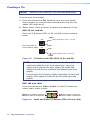
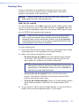
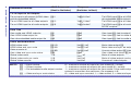
E
Remote connector — Connect an RS-232 capable host
device such as a computer or a touch panel control to this
3.5 mm 3-pole captive screw connector to configure and
control the switcher via SIS commands.
Connect the 9-pin connector end of the RS-232 cable to the
serial port of your computer or control system.
Figure 5. Wiring the Remote RS-232 Connector
See SIS Commands on page 30 for denitions of some of the
basic SIS commands to set up the DXP.
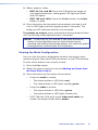
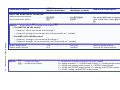
F
LAN port — Connect a computer, a network switch, or a
control system to this RJ-45 connector. With the Ethernet
connection, you can use a computer to configure and control
the networked switcher with SIS commands, the PCS
configuration program, or the embedded HTML page.

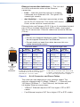
9DXP HD 4K Series • Setup
Ethernet connection indicators — The Link and
Act LEDs indicate the status of the Ethernet
connection.
• Link — Indicates that the switcher is properly
connected to an Ethernet LAN. This green LED
should light steadily.
• Act (Activity) — Indicates transmission of data
on the RJ-45 connector. This amber LED should
icker as the switcher communicates.
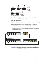
Ethernet links use Category (CAT) 3, 5e, or 6 unshielded twisted
pair (UTP) or shielded twisted pair (STP) cables, terminated
with RJ-45 connectors. Ethernet cables are limited to 328 feet
(100 m).
NOTES:
• Do not use standard telephone cables. Telephone cables
do not support Ethernet or Fast Ethernet.
• Do not stretch or bend the cables because this can
cause transmission errors.
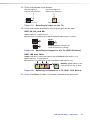
A cable that is wired as T568A at one end
and T568B at the other (Tx and Rx pairs
reversed) is a "crossover" cable.
A cable that is wired the same at both ends
is called a "straight-through" cable, because
no pin or pair assignments are swapped.
RJ-45
Connector
Insert Twisted
Pair Wires
12345678
Pins:
Crossover Cable Straight-through Cable
Pin
1
2
3
4
5
6
7
8
Wire Color
White-green
Green
White-orange
Blue
White-blue
Orange
White-brown
Brown
Wire Color
T568A
T568B
End 1 End 2End 1End 2
White-orange
Orange
White-green
Blue
White-blue
Green
White-brown
Brown
Pin
1
2
3
4
5
6
7
8
Wire Color
Blue
White-blue
White-brown
Brown
Wire Color
T568B
T568B
White-orangeWhite-orange
OrangeOrange
White-greenWhite-green
Blue
White-blue
GreenGreen
White-brown
Brown
Figure 6. RJ-45 Connector and Pinout Tables
The cable you use depends on your network speed. The
switcher supports both 10 Mbps (10Base-T — Ethernet) and
100 Mbps (100Base-T — Fast Ethernet), half-duplex and
full-duplex Ethernet connections.
• 10Base-T Ethernet requires CAT 3 or higher UTP or STP
cables.
• Fast Ethernet requires CAT 5e or higher UTP or STP cables.
LAN
DXP 1616
Series
LAN
DXP 88 Series

10 DXP HD 4K Series • Setup
Terminate the Ethernet cable as required:
• Network connection — Wire as a patch (straight-through)
cable.
• Computer or control system connection — Wire as a
crossover cable.
Default Ethernet settings:
• IP address: 192.168.254.254
• Subnet mask: 255.255.0.0
• Gateway: 0.0.0.0
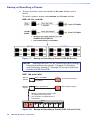
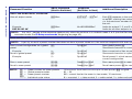
G
Analog audio outputs — Connect powered speakers, an
amplifier, or other audio output device to these 5-pole 3.5 mm
captive screw connectors for 2-ch stereo analog audio output.
These connectors can de-embed 2-ch LPCM audio that was
routed from any DXP HDMI input and convert it to a stereo
analog signal.
Do not tin the wires!
Balanced Audio Output
Tip
Ring
Tip
Ring
Slee
ves
Unbalanced Audio Output
Tip
No Ground Here
No Ground Here
Tip
Sleeves
LR
LR
Figure 7. Wiring the Captive Screw Audio Output
Connectors
The DXP 168 and 1616 have four analog audio output
connectors while the DXP 44, 84, and 88 have two.
ATTENTION:
• For unbalanced audio output, connect the sleeves to
the ground contact. DO NOT connect the sleeves to the
negative (-) contacts.
• Pour l’audio asymétrique, connectez les manchons au
contact au sol. Ne PAS connecter les manchons aux
contacts négatifs (–).
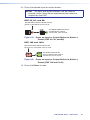
H
S/PDIF outputs (Sony/Philips Digital Interface Format) — Use
75 ohm digital audio cables to connect audio signal
processors (such as the Extron SSP 7.1 Surround Sound
Processor) or other compatible devices to these female
RCA connectors. The connected processor then converts
digital signals from these ports to analog for encoded standard
definition bitstream audio for Dolby or DTS multi-channel
surround sound.
S/PDIF

11DXP HD 4K Series • Setup
Tip (+)
Sleeve ( )
RCA Connector
Figure 8. RCA Plug for S/PDIF Audio Outputs
The DXP 168 and 1616 have four S/PDIF connectors while the
DXP 44, 84, and 88 have two.
I
AC power connector — Plug a standard IEC power cord into
this connector to connect the switcher to a 100 VAC to 240
VAC, 50 or 60 Hz power source.
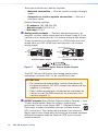
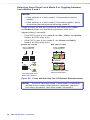
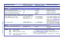
Securing HDMI Cables with the LockIt HDMI Cable Lacing
Bracket
Use a LockIt HDMI Cable Lacing Bracket to securely fasten each
HDMI cable to the switcher as follows.
1. Plug the HDMI cable into
the panel connection (see the
illustration at right,
1
).
2. Loosen the HDMI connection
mounting screw from the
panel enough to allow the
LockIt lacing bracket to be
placed over it (
2
). The screw
does not have to be removed.
3. Place the LockIt lacing
bracket (
3
) on the screw and
against the HDMI connector,
then tighten the screw to
secure the bracket.
ATTENTION:
• Do not overtighten the HDMI connector mounting screw.
The shield it fastens to is very thin and can easily be
stripped.
• Ne serrez pas trop la vis de montage du connecteur
HDMI. Le blindage auquel elle est attachée est très n et
peut facilement être dénudé.
4. Loosely place the included tie wrap around the HDMI connector
and the LockIt lacing bracket as shown (
4
).
5. While holding the connector securely against the lacing
bracket, use pliers or similar tool to tighten the tie wrap, then
remove any excess length.
3
33
11
44
22

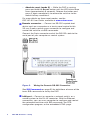
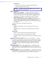
12 DXP HD 4K Series • Setup
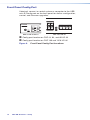
Front Panel Config Port
If desired, connect a control system or computer to the USB
mini-B Cong port on the front panel for device conguration,
control, and rmware upgrades.
Extron
CONFIG
INP
1
5
2
6
AA
C O N T R O L
CONFIG
15 16
15 16
ESCVIEW
PRESETENTER
BB
DXP 88 HD 4K Series DXP 1616 HD 4K
A
Config port location on DXP 44, 84, and 88 HD 4K
B
Config port location on DXP 168 and 1616 HD 4K
Figure 9. Front Panel Config Port Locations

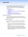
DXP HD 4K Series • Operation 13
Operation
This section describes the DXP HD 4K series front panel controls
and the procedures to congure and begin to operate the
switchers. For additional operations and more details, see the
DXP HD 4K Series User Guide, available at www.extron.com.
Topics include:
• Front Panel Features
• Creating a Tie
• Locking and Unlocking the Front Panel (Executive Mode)
• Viewing Ties
• Muting an Output from the Front Panel
• Selecting the Remote RS-232 Port Baud Rate
Front Panel Features
The front panel buttons of both the DXP 1616 series and the
DXP 88 series are grouped into two sets, with the input and output
buttons located on the left side of the control panel and the control
buttons on the right side.
Buttons and LEDs
The front panel buttons have multiple primary and secondary
functions. For more details on these functions, see the DXP user
guide.
• The DXP 44, 84, and 88 have non-illuminated buttons, each
of which has an LED beside it. These bicolor (red and green)
LEDs light green when video is selected and red when audio is
selected.
• The DXP 168 and 1616 have illuminated tricolor (red, green,
and amber) push buttons that can be labeled with text or
graphics. You can set these buttons to have amber background
illumination all the time, or you can disable the illumination (see
"Setting the Button Background Illumination" in the DXP user
guide for the procedure).

14 DXP HD 4K Series • Operation
DXP HD 4K Front Panels
Figure 10 shows a DXP 88 HD 4K front panel. The DXP 44 and 84
front panels are identical to this one.
NOTE: Although the DXP 44 and 84 both have eight input and
eight output buttons, not all these buttons are functional:
• DXP 44: Only input and output buttons 1 through 4 are
functional, except for creating and recalling presets (see
Saving or Recalling a Preset on page 20).
• DXP 84: Only output buttons 1 through 4 are functional,
except for creating and recalling presets (see Saving or
Recalling a Preset).
AA
D
D
E
E
Extron
CONFIG
INPUTS
1
5
2
6
3
7
4
8
OUTPUTS
1
5
2
6
3
7
4
8
ENTER PRESET ESC I/O
VIDEO
AUDIO
INPUTS
SIGNAL
HDCP
12345678
DIGITAL CROSSPOINT MATRIX SWITCHER
DXP HD 4K SERIES
BB CC
HH
FF
GG
Figure 10. DXP 88 HD 4K Front Panel
Figure 11 shows a DXP 1616 HD 4K front panel. The DXP 168 front
panel is identical to this one.
NOTE: Although the DXP 168 has 16 input and output
buttons, output buttons 9 through 16 are not functional
except for creating and recalling presets (see Saving or
Recalling a Preset).
DXP HD 4K SERIES
DIGITAL CROSSPOINT MATRIX SWITCHER
C O N T R O L I/O
CONFIG
1
2
3
4
5
6
7 8
OUTPUTS
1
2
3
4
5
6 7 8
9
10
11
12
13
14
15 16
9
10
11
12
13
14 15 16
INPUTS
AUDIOVIDEO
ESCVIEW
PRESETENTER
DD
A
A
BB
CC
EE
Figure 11. DXP 1616 HD 4K Front Panel
A
Config port
E
I/O buttons
B
Input buttons
F
Audio and Video LEDs
C
Output buttons
G
Signal LEDs
D
Control buttons
H
HDCP LEDs
Page is loading ...
Page is loading ...
Page is loading ...
Page is loading ...
Page is loading ...
Page is loading ...
Page is loading ...
Page is loading ...
Page is loading ...
Page is loading ...
Page is loading ...
Page is loading ...
Page is loading ...
Page is loading ...
Page is loading ...
Page is loading ...
Page is loading ...
Page is loading ...
Page is loading ...
Page is loading ...
Page is loading ...
Page is loading ...
Page is loading ...
Page is loading ...
Page is loading ...
Page is loading ...
Page is loading ...
Page is loading ...
Page is loading ...
Page is loading ...
Page is loading ...
Page is loading ...
Page is loading ...
Page is loading ...
Page is loading ...
Page is loading ...
Page is loading ...
Page is loading ...
Page is loading ...
Page is loading ...
-
 1
1
-
 2
2
-
 3
3
-
 4
4
-
 5
5
-
 6
6
-
 7
7
-
 8
8
-
 9
9
-
 10
10
-
 11
11
-
 12
12
-
 13
13
-
 14
14
-
 15
15
-
 16
16
-
 17
17
-
 18
18
-
 19
19
-
 20
20
-
 21
21
-
 22
22
-
 23
23
-
 24
24
-
 25
25
-
 26
26
-
 27
27
-
 28
28
-
 29
29
-
 30
30
-
 31
31
-
 32
32
-
 33
33
-
 34
34
-
 35
35
-
 36
36
-
 37
37
-
 38
38
-
 39
39
-
 40
40
-
 41
41
-
 42
42
-
 43
43
-
 44
44
-
 45
45
-
 46
46
-
 47
47
-
 48
48
-
 49
49
-
 50
50
-
 51
51
-
 52
52
-
 53
53
-
 54
54
-
 55
55
-
 56
56
-
 57
57
-
 58
58
-
 59
59
-
 60
60


Extron DXP HD 4K Series User manual
- Category
- Video switches
- Type
- User manual
Ask a question and I''ll find the answer in the document
Finding information in a document is now easier with AI
Related papers
-
Extron DXP HD 4K PLUS Series User manual
-
-
 Extron electronics SW HD 4K PLUS Series User manual
-
 Extron electronics DXP 1616 HD 4K PLUS Series User manual
-
Extron electronics HDMI 230 D User manual
-
Extron electronics DTP CrossPoint 84 User manual
-
Extron DXP HDMI Series Owner's manual
-
-
-
Extron electronics DTP HDMI 4K 330 Rx User manual


Other documents
-
Legrand 40744 Owner's manual
-
 Extron electronics DXP DVI Pro User manual
-
Extron electronic DTP T USW 233 User manual
-
 Extron electronics DTP CrossPoint 84 IPCP User guide
-
-
 Extron electronics DTP T SW4 HD 4K User manual
-
 Weltron WA-612E User manual
-
AOpen DXPS-U Owner's manual
-
-
 Extron electronics MPA 401-100V User manual


