
QUICK REFERENCE DATA
DS4BD Series Residential Split System Air Conditioner
Table 1. Electrical Specifications & Physical Data
MODEL NUMBER: DS4BD- 018KB 024KB 030KB 036KB 042KB 048KB 060KB
Electrical
Data
Volts-Cycles Phase (1) 208 / 230 - 60 - 1
Total Amps 9.3 13.5 14.8 18.0 19.4 23.2 27.8
Delay Fuse Max. (2) 20 25 30 35 40 50 60
Min. Circuit Ampacity 11.6 16.7 18.3 22.2 23.9 28.7 34.4
Component
Data
Coil
Area 8.3 8.3 10.0 10.0 15.3 15.3 17.9
Rows-FPI 1-18
Tube Dia. Micro-Channel
Fan Motor
Type PSC
Amps 0.35 0.7 0.7 1.4 1.5 1.5 1.5
HP 0.05 0.1 0.1 0.25 0.25 0.25 0.25
Compressor Data
RLA 9.0 12.8 14.1 16.6 17.9 21.8 26.4
LRA 48.0 58.3 73.0 79.0 112.0 117.0 134.0
REFRIGERANT SUCTION LINE O.D
NOTE: Liquid line is 3/8” O.D. for entire length.
0 - 24 ft. 3/4” 3/4” 3/4” 3/4” 7/8” 7/8” 7/8”
25 - 39 ft. 3/4” 3/4” 3/4” 7/8” (3) 7/8” 7/8” 1-1/8” (4)
40 - 75 ft. 3/4” 3/4” 3/4” 7/8” (3) 7/8” 7/8” 1-1/8” (4)
REFRIGERANT CHARGE
R-410A in ounces for outdoor unit & 15' Lineset. (5)
40.4 46.0 40.0 51.0 81.0 76.0 105.6
APPROXIMATE WEIGHT (LBS.)
Net 109 125 138 140 179 179 188
Ship 114 130 144 146 187 187 197
(1) Operating Voltage Range: 187v min. — 253v max.
(2) HACR Type Circuit Breakers may be used.
(3) Requires 7/8" to 3/4" reducer from line to unit.
(4) Requires 7/8" to 1-1/8" reducer from line to unit.
(5) Additional charge for line sets above 15 feet. Values based on
suction line as follows with 3/8" liquid line.
(a) 3/4" = 0.6 oz. per additional foot.
(b) 7/8" = 0.7 oz. per additional foot.
(c) 1 1/8" = 0.8 oz. per additional foot
.
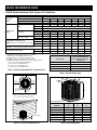
Table 3. Unit Dimensions
MODEL
NUMBER
HEIGHT
(H)
WIDTH
(W)
DEPTH
(D)
DS4BD-018KB 23 1/2" 22 3/4" 22 3/4"
DS4BD-024KB 23 1/2" 22 3/4" 22 3/4"
DS4BD-030KB 27 1/2" 22 3/4" 22 3/4"
DS4BD-036KB 27 1/2" 22 3/4" 22 3/4"
DS4BD-042KB 27 1/2" 30 3/4" 30 3/4"
DS4BD-048KB 27 1/2" 30 3/4" 30 3/4"
DS4BD-060KB 31 1/2" 30 3/4" 30 3/4"
D
H
W
Model DS4BD Shown
Figure 1. Clearance Requirements
2” Mounting Pad
48”
24" for
Service Access
12" or 18”
See Note
12" or 18”
See Note
DO NOT
OBSTRUCT
TOP OF UNIT
NOTE: Units require full perimeter clearances.
Installer must maintain 18” between two units
or 12” between single unit and structure.
6” from Building
or Structure
Table 2. Control Wiring (24V)
Wire Gauge
Recommended Maximum
Wire Length (FT) from Unit
to Thermostat
22 45
20 70
18 115
16 180

7096150 (Replaces 7094530)
Instructions:
1. Find the column for the model of outdoor unit that is being installed.
2. Find the row for the model of the indoor unit that is being installed.
3. Find the cell in the table in which this row and column meet. In this cell
the appropriate orifice / TXV and charge addition for this match are listed.
If the text in this cell is BOLD, then a change of orifice is necessary.
4. If a change in restrictor is necessary, then the appropriate restrictor will
already be supplied with the outdoor unit.
Examples:
• FortheDS4BD-030KB/C5(B,D)A-X30U-Bmatch,theappropriateTXV
is the 669565 and 36 ounces of charge will need to be added. (CHANGE
IN CHARGE)
• FortheDS4BD-024KB/C8(B,D)AM01830U-Bmatch,theappropriate
restrictor is the .055 and no additional charge needs to be added.
(CHANGEINRESTRICTOR)
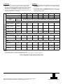
Table 4. Restrictor or TXV / Charge Addition (Oz)
ID Restrictor Installed With ID Unit
Model Number: DS4BD 018KB 024KB 030KB 036KB 042KB 048KB 060KB
ID Restrictor Supplied With OD Unit: 0.048 0.055
-- -- -- -- --
Outdoor Unit BOM Charge (Oz.) 40.4 46 40 51 81 76 105.6
MODELS
SUPPLIED
WITH ID
REQUIRED RESTRICTOR OR TXV / CHARGE ADDITION (OZ) / RATED AIRFLOW (SCFM)
C5
C5(B,D)A-X25U-B 669564
669564
(30 / 525)
669564
(24 / 700)
-- -- -- -- --
C5(B,D)A-X30U-B 669565 -- --
669565
(36 / 950)
-- -- -- --
C5(B,D)A-X37U-B 669566 -- -- --
669566
(21 / 1100)
-- -- --
C5(B,D)A-X42U-B 669567 -- -- -- --
669567
(12 / 1275)
-- --
C8
C8(B,D)AM01830U-B 0.061
0.048
(0 / 535)
0.055
(0 / 705)
0.061
(0 / 960)
-- -- -- --
C8(B,D)AM036U-B 0.067 -- -- --
0.067
(0 / 1190)
-- -- --
CM4B
CM4B-53U TXV -- -- -- --
TXV
(0 / 1250)
-- --
CM4B-54U TXV -- -- -- -- --
TXV
(0 / 1450)
TXV
(0 / 1450)
CM4B-56U TXV -- -- -- -- --
TXV
(10 / 1500)
TXV
(0 / 1600)
NOTES:
• The charges listed are only valid for the standard 15’ lineset.
• Numberslistedas0.***arerestrictordiameters,whilenumberslistedas669***areTXVpartnumbers.
Specifications & illustrations subject to change without notice or incurring obligations (07/15).
O’Fallon, MO, © Nortek Global HVAC LLC 2015. All Rights Reserved.
-
 1
1
-
 2
2


Miller DS4(B,Q)D-KB/KC User guide
- Type
- User guide
- This manual is also suitable for
Ask a question and I''ll find the answer in the document
Finding information in a document is now easier with AI
Related papers
Other documents
-
Broan FS4BD-KA/B User guide
-
-
Unbranded PSA4BD-KA/B User guide
-
-
-
Broan ES4BD/ES4QD User guide
-
-
-
-