
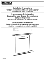
Installation Instructions
Instrucciones de instalaci6n
Instructions d'installation
English / Espafiol / Fran_;ais
i<enmoreo
(Moddos con tina gigante de plast_co}
@
(Mod@les 6 tr@sgrande cure en p_®stique}
co pto r
P/N WlO282552B
Sears Brands Management Corporation
Hoffman Estates, IL 60179 U.S.A.
www.kenmore.com
www.sears.com
www.sears.ca

TABLEOF CONTENTS
DISHWASHER SAFETY .................................................................. 2
INSTALLATION REQUIREMENTS ................................................. 3
Tools and Parts ........................................................................................ 3
Location Requirements ........................................................................... 3
Drain Requirements ................................................................................ 5
Water Supply Requirements ................................................................ 5
Electrical Requirements ......................................................................... 5
JNDICE ........................................................................................ 16
TABLE DES MATIi:RES ................................................................. 31
INSTALLATION INSTRUCTIONS ................................................... 6
Prepare cabinet opening using existing utility hookups .................. 6
Prepare cabinet opening where there are no existing
utility hookups .......................................................................................... 7
Prepare Dishwasher ................................................................................ 9
Make Electrical Connection ................................................................. 12
Connect to water supply ...................................................................... 13
Connect to drain ................................................................................... 14
Secure dishwasher in cabinet opening ............................................. 14
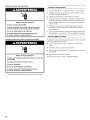
DISHWASHER SAFETY
Your safety and the safety of others are very important.
We have provided many important safety messages in this manual and on your appliance. Always read and obey all safety
messages.
This is the safety alert symbol.
This symbol alerts you to potential hazards that can kill or hurt you and others.
All safety messages will follow the safety alert symbol and either the word "DANGER" or "WARNING."
These words mean:
You can be killed or seriously injured if you don't immediately
follow instructions.
You can be killed or seriously injured if you don't follow
instructions.
All safety messages will tell you what the potential hazard is, tell you how to reduce the chance of injury, and tell you what can
happen if the instructions are not followed.
Tip Over Hazard
Do not use dishwasher until completely instal|ed.
Do not push down on open door.
Doing so can result in serious injury or cuts.
You need to;
• Slowly open dishwasher door while someone grasps the rear of
the dishwasher. Remove shipping materials, drain hose and
lower rack. Close dishwasher door until latched.
• Observe all governing codes and ordinances.
• Install this dishwasher as specified in these instructions.
• Installation should be performed by a qualified service
technician. The dishwasher must be installed to meet all
electrical and plumbing national and local codes and
ordinances.
2

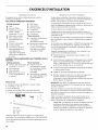
INSTALLATION REQUIREMENTS
Gather the required tools and parts before starting installation.
All installations
Tools needed:
• Pliers
• Phillips screwdriver
• 5,_d' and 1/4" nut drivers or
hex sockets
• Measuring tape or ruler
• 10" adjustable wrench that
opens to 11/8'' (2.9 cm)
• Flat-blade screwdriver
• Utility knife
• 2 twist-on wire connectors
which are the proper size to
connect your household
wiring to 16-gauge wiring
in dishwasher
In addition, for new installations
Tools needed:
• Cordless drill with 1/2", 3/4",
and 11/2'' hole saw bits
• Small tubing cutter
• Wire stripper
• 11/2'' to 2" screw-type clamp
if connecting to waste-tee
• Small level
• Flashlight
• Shallow pan
• s/8" open-end wrench
• Bath towel
• Wood block
Parts Needed:
Shims (if installed with
built-up floor)
3/8" Compr x _" hose
fitting. Contact your local
Sears Store to purchase Kit
Number 11000.
Parts needed:
• Copper tubing (3/8"
recommended) or flexible
stainless steel braided fill
line
• Clamp connector or
conduit connector to fit a
7/8" (2.2 cm) diameter hole
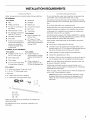
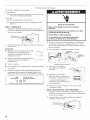
Parts supplied
A. 2 - drain hose clamps, 1 large and 1 small
B. 2 - # 10 x 1/2" Phillips-head screws
C. Drain hose
D. 2 - undercounter side mount brackets
E. 2 - undercounter mounting brackets (top)
B
C
D
Do not run drain lines, water lines or electrical wiring where they
can interfere with or contact dishwasher motor or legs.
The location where the dishwasher will be installed must provide
clearance between motor and flooring. Motor should not touch the
floor.
Do not install dishwasher over carpeted flooring.
Shelter dishwasher and water lines leading to dishwasher against
freezing. Damage from freezing is not covered by the warranty.
A side panel kit is available from your dealer for installing your
dishwasher at the end of your cabinetry.
A moisture barrier accessory (Part Number 4396277) is available
from your dealer for installing underneath the countertop. This may
also be obtained by calling 1-800-4MY-HOME.
Check location where dishwasher will be installed. The location
must provide:
• easy access to water, electricity and drain.
• convenient access for loading and unloading dishes. Corner
locations require a 2" (5.1 cm) minimum clearance between the
side of the dishwasher door and the wall or cabinet.
• square opening for proper operation and appearance.
• cabinet front perpendicular to floor.
• level floor. (If floor at front of opening is not level with floor at
rear of opening, shims may be needed to level dishwasher.)
NOTE: To avoid shifting during dishwasher operation, shims must
be securely attached to the floor.
If dishwasher will be left unused for a period of time or in a
location where it may be subject to freezing, have it winterized by
authorized service personnel.
Make sure pipes, wires and drain hose are within the shaded area
shown in the "Cutout dimensions" section.
Helpful Tip: If the floor in the dishwasher opening is uneven
(example: tile flooring only partway into opening), you will
need to be exact in measuring dimensions and in leveling
dishwasher.
Make sure all these parts are included. If not included, call
1-800-4MY-HOME.
See separate parts list for accessories available for your
dishwasher.

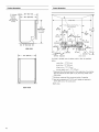
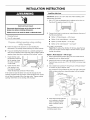
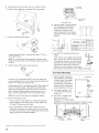
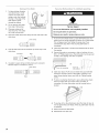
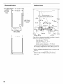
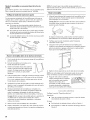
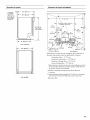
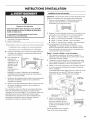
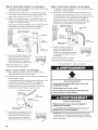
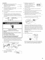
Productdimensions
Cutout dimensions
s/_,,(1.gcm)
insulation-
may be
compressed
(not used on all
models)
25%" (64.1 cm)
241/2"(62.2 cm)
|
21" (53.3 cm) --_
33%"
(86 cm) rain.
with wheels
removed
SIDE ViEW
•_-- 23%" (60.6 cm)
_ " 24" (61cm)_*
All surfaces must be free
from intrusions
(4Acm)¢ (10.8cm)$ clear area :1;
Cut holes in shaded area of cabinet walls or floor as specified
below:
water line - 1/2" (1.3 cm)
drain line - ]1/2" {3.8 cm)
direct wire - 3/4" (1.9 cm)
power supply cord - 11/2'' (3.8 cm)
_Measured from the lowest point on the underside of countertop.
May be reduced to 337/8'' (86 cm) by removing wheels from
dishwasher.
_Minimum, measured from narrowest point of opening.
¢'_¢May be increased to 67/8'' (17.5 cm) if height of opening is
341/2 '' (87.6 cm) at its lowest point.
SBoth sides
REAR ViEW
4

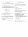
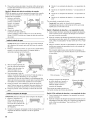
Use the new drain hose supplied with your dishwasher. If this is
not long enough, use a new drain hose with a maximum length
of 12 ft (3.7 m) that meets all current AHAM/IAPMO test
standards, is resistant to heat and detergent, and fits the 1"
(2.5 cm) drain connector of the dishwasher.
Connect drain hose to waste tee or disposer inlet above drain
trap in house plumbing and 20" (50.8 cm) minimum above the
floor. It is recommended that the drain hose either be looped
up and securely fastened to the underside of the counter, or be
connected to an air gap.
Air gap
IL
• Use an air gap if the drain hose is connected to house plumbing
lower than 20" (50.8 cm) above subfloor or floor.
• Use 1/2" minimum I.D. drain line fittings.
_4 _X__ .... _ _ _ ,_
W_:_!_e_' s_spp v _(eq_,,}®_'et<_set_:s
• A hot water line with 20 to 120 psi (138 to 862 kPa) water
pressure.
• 120°F (49°C) water at dishwasher.
• 3/8" O.D. copper tubing with compression fitting or flexible
stainless steel braided fill line (1/2" minimum plastic tubing is not
recommended).
• A 90 ° elbow with s/s" N.P.T. external pipe threads on one end.
Do not solder within 6" (15.2 cm) of water inlet valve.
Contact a qualified electrician.
Assure that the electrical installation is adequate and in
conformance with all national and local codes and ordinances.
You must have:
• 120-volt, 60 Hz, AC-only, 15- or 20- amp, fused electrical
supply.
• Copper wire only.
We recommend:
• A time-delay fuse or circuit breaker.
• A separate circuit.
If direct wiring dishwasher:
• Use flexible, armored or nonmetallic sheathed, copper wire
with grounding wire that meets the wiring requirements for your
home and local codes and ordinances.
• Use strain relief method provided with house wiring junction
box or install a UL Listed/CSA Approved clamp connector to
the house wiring junction box. If using conduit, use a UL Listed/
CSA Approved strain relief.
If connecting dishwasher with a power supply cord:
• Use Power Supply Cord Kit (Part Number 4317824) marked for
use with dishwashers. Kit contents include:
- Volex, Inc., UL Listed 16 gauge 3 wire power supply cord with
3 prong grounded plug.
- Neer C-500 z/s" strain relief.
- 3 wire connectors.
- Part Number 302797 grommet
Follow the kit instructions for installing the power supply cord.
• Power supply cord must plug into a mating 3 prong, grounded
outlet, located in the cabinet next to the dishwasher opening.
Outlet must meet all local codes and ordinances.

INSTALLATION INSTRUCTIONS
Electrical Shock Hazard
Disconnect electrical power at the fuse box or circuit
breaker box before installing dishwasher.
Failure to do so can result in death or electrical shock.
1. Disconnect power.
2. Turn off water supply.
Follow the steps in this section if you are installing the
dishwasher in an existing cabinet opening with utility hookups.
• If you are installing the dishwasher in a cabinet opening that
does not have hookups, follow the steps under "Prepare cabinet
opening where there are no existing utility hookups" section.
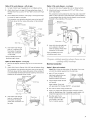
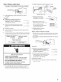
2.
Check that the water H
line reaches to the front ___ Water
left of opening where line
the water connection / >
will be made .............................._/_
Check that the direct
wire reaches to the
front right of opening
where the electrical connection will be made.
If the water line and the direct wire reach far enough into the
opening, proceed to the next section "Install the drain hose." If they
do not reach far enough, follow the steps under "Prepare cabinet
opening where there are no existing utility hookups."
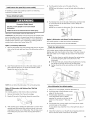
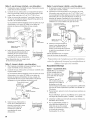
Install the drain hose
IMPORTANT: Always use a new drain hose when installing a new
replacement dishwasher.
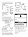
1. Drill a 11/2'' (3.8 cm) diameter hole in cabinet wall or floor on
the side of the opening closest to the sink.
2. Connect drain hose to waste tee or waste disposer using one of
the following methods:
• Option 1, Waste disposer - with air gap
• Option 2, No waste disposer - with air gap
• Option 3, Waste disposer - no air gap _
• Option 4, No waste disposer - no air gap _
_An
air gap is recommended.
Helpful Tip: To reduce the vibration of the hose, keep the hose
away from the floor and the edge of the hole where it passes
through the cabinet.
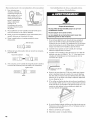
Option 1, Waste disposer - with air gap:
1. Remove the disposer knockout plug. Cut end of drain hose if
needed (do not cut ribbed section).
2. Attach drain hose to air gap with large spring-type clamp. If
the drain hose was cut, use a 11/2'' to 2" (3.8 to 5 cm) screw-type
clamp _.
3. Use a rubber hose connector _ with spring or screwtype clamps _
to connect air gap to disposer inlet.
This connection must be before the drain trap and at least 20"
(50.8 cm) above the floor where dishwasher will be installed.
gap
Large
clamp
hose
Drain trap
4. Insert drain hose through hole
cut in cabinet to the front
center of opening where
drain connection will be
made.
_Parts available from local
plumbing supply stores.
6

Option 2, No waste disposer - with air gap:
1. Cut end of drain hose if needed (do not cut ribbed section).
2. Attach drain hose to air gap with large spring-type clamp. If
the drain hose was cut, use a 11/2'' to 2" (3.8 to 5 cm) screw-type
clamp _.
3. Use a rubber hose connector _ with spring or screwtype clamps _
to connect air gap to waste tee.
This connection must be before the drain trap and at least 20"
(50.8 cm) above the floor where dishwasher will be installed.
Rubber hose
connector
gap
Option 4, No waste disposer - no air gap:
1. Cut end of drain hose if needed (do not cut ribbed section).
2. Attach drain hose to waste tee with 11/2'' to 2" (3.8 to 5 cm)
screw-type clamp _.
This connection must be before the drain trap and at least 20"
(50.8 cm) above the floor where dishwasher will be installed. It
is recommended that the drain hose be looped up and securely
fastened to the underside of the counter.
Drain hose -
cut here if needed
Screw-type
clamp
Large
clamp
Drain
Drain trap _ hose
4. Insert drain hose through
hole cut in cabinet to the
front center of opening
where drain connection
will be made.
_Parts available from local
plumbing supply stores.
Option 3, Waste disposer - no air gap:
1. Remove the disposer knockout plug. Do not cut end of drain
hose.
2.
Attach drain hose to disposer inlet with large springtype clamp.
This connection must be before the drain trap and at least 20"
(50.8 cm) above the floor where dishwasher will be installed. It
is recommended that the drain hose be looped up and securely
fastened to the underside of the counter.
Large spring-type J
_ Drain hose
D '
3.
Insert drain hose through
hole cut in cabinet to the
front center of opening
where drain connection will
be made.
Drain hose
tee
Drain
3.
Insert drain hose through hole
cut in cabinet to the front
center of opening where drain
connection will be made.
_Parts available from local
plumbing supply stores.
Drain hose
hose
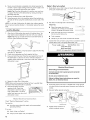
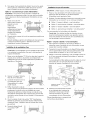
Electrical connection
Option 1, Direct wire method:
Helpful Tip: Wiring the dishwasher will be easier if you route
wire into the cabinet opening from the right side.
1. Drill a 3/4" (1.9 cm) hole in
right-hand cabinet side, rear
or floor. Preferred and
optional locations are shown.
2. Wood cabinet: Sand the hole
until smooth.
Optional Preferred
locations locations
3. Run wire into house wiring junction box.
4. Install a UL Listed/CSA Approved clamp connector (strain
relief) for flexible-type wire. If installing conduit, attach a UL
Listed/CSA Approved strain relief to the junction box.
5. Run other end of wire
through cabinet hole. Cable
must extend to the right
front of cabinet opening.
Metal cabinet: Cover hole
with grommet, (Part Number 302797 - not provided.)

Option 2, Power supply cord method:
NOTE: A mating, 3 prong, ground-type wall receptacle is required
in a cabinet next to the dishwasher opening.
1. Drill a 11/2'' (3.8 cm)
hole in the cabinet
rear or side.
Preferred and
optional locations
are shown.
Optional Preferred
locations locations
2. Wood cabinet:
Sand the hole until
smooth.
Metal cabinet: Cover hole with grommet (Part Number
302797) included with power supply cord kit.
Install the water line
Helpful Tip: Routing the water line through the left side of
cabinet opening will make water connection easier.
Drill a minimum 1/2" (1.3 cm) hole in the cabinet side, rear or
floor. Preferred and optional locations are shown.
Optional Preferred
locations locations
2. Measure overall length
of copper tubing
required.
3. Attach copper tubing
to the water line with a
manual shutoff valve.
4.
Copper
tubing
Slowly feed copper
tubing through hole in
cabinet. Copper tubing will bend and kink easily, so be gentle.
The copper tubing should be far enough into the cabinet
opening to connect it to dishwasher inlet on the front left of the
dishwasher.
5. Turn water shutoff valve to "ON" position. Flush water into a
shallow pan to get rid of particles that may clog the inlet valve.
6. Turn shutoff valve to "OFF" position.
Install the drain hose
IMPORTANT: Always use a new drain hose.
1. Drill a 11/2'' (3.8 cm)
diameter hole in
cabinet wall or floor
on the side of the
opening closest to the
sink.
2.
J
Connect drain hose to waste tee or waste disposer using one of
the following methods:
• Option 1, Waste disposer - with air gap
• Option 2, No waste disposer - with air gap
• Option 3, Waste disposer - no air gap _
• Option 4, No waste disposer - no air gap _
_An air gap is recommended.
Helpful Tip: To reduce the vibration of the hose, keep the hose
away from the floor and the edge of the hole where it passes
through the cabinet.
Option 1, Waste disposer - with air gap:
1. Remove the disposer knockout plug. Cut end of drain hose if
needed (do not cut ribbed section).
2. Attach drain hose to air gap with large spring-type clamp. If
the drain hose was cut, use a 11/2'' to 2" (3.8 to 5 cm) screw-type
clamp _.
3. Use a rubber hose connector _ with spring or screwtype clamps _
to connect air gap to disposer inlet.
This connection must be before the drain trap and at least 20"
(50.8 cm) above the floor where dishwasher will be installed.
gap
Large
clamp
hose
Drain trap
4. Insert drain hose through
hole cut in cabinet to the
front center of opening
where drain connection will
be made.
_Parts available from local
plumbing supply stores.
Drain hose

Option 2, No waste disposer - with air gap:
1. Cut end of drain hose if needed (do not cut ribbed section).
2. Attach drain hose to air gap with large spring-type clamp. If
the drain hose was cut, use a 11/2'' to 2" (3.8 to 5 cm) screw-type
clamp _.
3. Use a rubber hose connector _ with spring or screwtype clamps _
to connect air gap to waste tee.
This connection must be before the drain trap and at least 20"
(50.8 cm) above the floor where dishwasher will be installed.
Rubber hose
connector
gap
Option 4, No waste disposer - no air gap:
1. Cut end of drain hose if needed (do not cut ribbed section).
2. Attach drain hose to waste tee with 11/2'' to 2" (3.8 to 5 cm)
screw-type clamp _.
This connection must be before the drain trap and at least 20"
(50.8 cm) above the floor where dishwasher will be installed. It
is recommended that the drain hose be looped up and securely
fastened to the underside of the counter.
Drain hose -
cut here if needed
Screw-type
clamp
Large
clamp
Drain tra Drain
hose
4. Insert drain hose through
hole cut in cabinet to the
front center of opening
where drain connection will
be made.
_Parts available from local
plumbing supply stores.
Option 3, Waste disposer - no air gap:
1. Remove the disposer knockout plug. Do not cut end of drain
hose.
2.
Attach drain hose to disposer inlet with large springtype clamp.
This connection must be before the drain trap and at least 20"
(50.8 cm) above the floor where dishwasher will be installed. It
is recommended that the drain hose be looped up and securely
fastened to the underside of the counter.
Large spring-type J
Drain hose
Drain trap/ _ I--I
3.
Insert drain hose through
hole cut in cabinet to the
front center of opening
where drain connection will
be made.
tee
Drain
3. Insert drain hose through
hole cut in cabinet to the
front center of opening
where drain connection will
be made.
_Parts available from local
plumbing supply stores.
hose
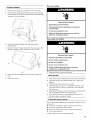
Tip Over Hazard
Do not use dishwasher until completely installed.
Do not push down on open door.
Doing so can result in serious injury or cuts.
Excessive Weight Hazard
Use two or more people to move and install
dishwasher,
Failure to do so can result in back or other injury.
Helpful Tip.- Put cardboard under dishwasher until it is installed
in cabinet opening. The cardboard will help avoid damage to
floor covering during installation.
1. Using 2 or more people, grasp the sides of dishwasher door
frame and put the dishwasher on its back, resting on top of the
corner posts.
2. Remove two screws attaching access panel and lower panel to
dishwasher using a 1/4" hex socket, nut driver or Phillips
screwdriver.

3. Removepanelsandsetpanelsasideonacoveredsurface.
4. Checkthatgroundingclipisattachedtothelowerpanel.
5.
Lower
panel
clip
Slide nut and ferrule onto tubing.
Copper tubing only: Slide nut, then ferrule, about 1" (2.5 cm)
onto copper tubing.
NOTE: To avoid vibration during operation, route the water
supply line so that it does not touch the dishwasher base, frame
or motor.
6. Add 90 ° elbow fitting to the water supply line.
Connect the 3/8" compression fitting to the water supply line
prior to installing the unit into the cabinet opening. Attach such
that the 3/4" connection is facing upward.
Copper tubing only: Put the tubing into the 90 ° elbow fitting as
far as it will go (the copper tubing bends and kinks easily).
Slide the nut and ferrule forward and start the nut onto the
elbow threads. Flexible braided connection: Secure nut to
elbow using 5/8" open ended wrench or adjustable wrench.
NOTE: Do not use Teflon_tape with compression fittings.
Remove terminal box cover.
- If you are direct wiring: Install a UL Listed/CSA Approved
clamp connector to the terminal box. If using conduit, use a
UL Listed/CSA Approved strain relief.
- If you are installing a power supply cord kit, do so now,
following kit instructions. The power supply cord kit must be
UL Listed and marked for use with dishwashers (that is, Power
Supply Cord Kit Part Number 4317824).
8°
. Terminal
I....................................................................................-_ box cover
_'_/ @' _ Cable clamp
connector
Dishwasher wires
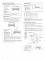
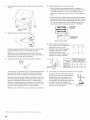
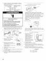
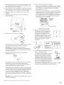
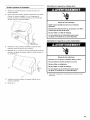
Measure height of cabinet opening
from underside of countertop to
floor where dishwasher will be
installed (you need the lowest
point). Check chart for that height
opening. Put wheels in the required
position.
9°
Minimum Wheel Number of
turns on
cutout height position front leg
34" (86.4cm) 1 10
341/4"(87 cm) 2 5
341/2" (87.6 cm) 3 O
Turn both front leveler legs to the same
height.
If the minimum cutout height is less than 34"
(86.4 cm), the rear wheels can be removed
for additional clearance. This will allow the
dishwasher to fit into a 337/8'' (86 cm) high
cutout, but the dishwasher will be more
difficult to move into position. If the wheels
Front leg
are removed, cover the floor when moving the dishwasher.
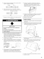
If you have built-upfloors
1.
2.
3°
Measure height of opening
from underside of countertop
to built-up floor. If the height
is at least 333/4" (85.7 cm),
the dishwasher will fit into the
opening without modification
to the countertop or flooring.
Put wheels in position 1 and
turn the front leveler legs up
all the way.
Add shims as needed in the
area shown to bring
dishwasher up to proper height.
/ Countertop
33%"
(85.7 cra)
rain,
/ up
NOTE: Shims must be securely attached to the floor to keep
them from moving when the dishwasher is operating.
t®Teflon is a registered trademark of E.I. Du Pont de Nemours and Company.
10

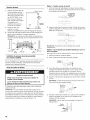
Install custom door panel kit (on some models)
If installing a custom door panel kit, install it now following
instructions included with kit.
Choose attachment option
Excessive Weight Hazard
Use two or more people to move and install
dishwasher.
Fai|ure to do so can result in back or other injury.
Using two or more people, stand the dishwasher up.
IMPORTANT: The dishwasher must be secured to the cabinet. There
are two brackets found in the parts bag. Attach the brackets to
the top of the dishwasher if the countertop is wood, laminate or
another similar surface. If your countertop is marble, granite or
another hard surface, install using Option #2.
Option 1, Countertop attachment
1. Remove the brackets from the package and place in the open
slots on the left and right-hand top of the dishwasher collar as
shown.
Tabs must
2.
Insert the bracket into the slot on the collar. Using a pair of
pliers, bend the tab down to secure the bracket in place.
Repeat this step for the other side.
)--1
..................................... ,.s .....................
NOTE: Do not attach the dishwasher. This will be done later.
Option 2, Dishwasher with Stainless Steel Tub Side
Attachment
(for marble, granite or other hard surface countertops)
1. Remove the brackets from the parts package.
2. Break off the end of the bracket along the scored line.
Score
(ine
3.
With another person holding the dishwasher to avoid it from
tipping, open dishwasher door, and place towel over pump
assembly and spray arm of dishwasher. This will stop screws
from falling into pump area when securing dishwasher to
cabinet.
4. Push the plastic buttons out of the side of the tub.
5°
NOTE: Save the buttons to cover the holes after dishwasher is
installed.
i
(
J
)
(
Plastic
button
Push bracket into slot on the side of dishwasher, and bend tab
in toward the side of the dishwasher so that it keeps the
bracket in place.
NOTE: Do not attach the dishwasher. This will be done later.
Bend
Option 3, Dishwasher with Plastic Tub Side Attachment
(for marble, granite or other hard surface countertops)
Order Mounting Bracket Kit Part Number 8212560.
Check door spring tension
With another person holding the dishwasher to keep it from
tipping, open and close the door a few times. If the door closes or
falls open under its own weight, the door tension will need to be
adjusted.
• If the door closes too quickly, decrease the spring tension
by moving the spring end toward the front of the
dishwasher.
• If the door falls open, increase the spring tension by moving
the spring end toward the back of the dishwasher.
• Springs should be in the same notches on left and right
sides.
Spring Move
spring end
/
Move dishwasher into cabinet opening
1.
2.
3°
4.
5°
Using two or more people, stand the dishwasher up.
Grasp the sides of the dishwasher at the
edges of the door panel.
Tilt dishwasher backward on wheels and
move dishwasher close to cabinet
opening. Do not push on the front of the
panel or on the console -- they may
dent.
If dishwasher has a power supply cord, insert power supply
cord into hole cut into cabinet.
If using direct wire, check that it is on the right front side of
opening.
Check that water line is on the left side of opening and drain
hose is near the center of the hole in the cabinet.
11

6. Slowly move dishwasher completely into cabinet opening. Do
not kink or pinch copper tubing, drain hose, power supply cord
or direct wire between dishwasher and cabinet.
Helpful Tip: Once the dishwasher is in position, you may have
to support the front of the dishwasher by raising, lowering or
shimming front feet.
7. Remove cardboard from under dishwasher.
8. Using the precut slots in the insulation, attach the insulation to
the sides of the tub using the molded hooks on each side of the
tub.
NOTE: It is all right if dishwasher fits tightly into cabinet opening.
Do not remove insulation blanket -- the blanket reduces the sound
level.
Level the dishwasher
1. Align front of dishwasher door panel with cabinet doors. You
may need to adjust alignment to be even with your cabinets.
Helpful Tip: Prop up one side of frame to hold dishwasher up
off floor when adjusting front legs.
With some installations, it may be easier to adjust the front leg
using the _6" hex head.
2. Check that leveling legs are firmly against the floor.
3. Close and latch the door. Place the level against the front of
the dishwasher to check to see if it is vertically aligned. If
needed, adjust leveling leg or add shims under rear wheel until
dishwasher is even.
f
4. Repeat for other side of dishwasher.
NOTE: Shims must be securely attached to floor to prohibit their
movement when the dishwasher is operated.
5. Place level against top front
opening of tub. Check that
dishwasher is level from side to
side. If dishwasher is not level,
adjust front legs up or down until
dishwasher is level.
Check "Electrical Requirements" section.
You need to:
• have the correct electrical supply and recommended
grounding method.
If you are:
• direct wiring, use Option 1
• using a power supply cord, use Option 2
Option 1, Direct wire method
1. Route direct wire so that it does not touch dishwasher motor or
lower part of dishwasher tub.
2. Pull direct wire through hole in terminal box.
Helpful Tip:
• Select the proper size twist-on
connectors to connect your household ......................................F',
wiring to 16-gauge dishwasher wiring. .................................................
_j
• Insert wire ends into twist-on connector.
Do not pre-twist bare wire.
• Twist connector.
• Gently tug on wires to be sure both are secured.
3. Connect the wires as follows using twist-on connectors sized to
connect direct wire to 16-gauge dishwasher wire:
Power supply wire: Terminal box wire:
white-Wall-white
black_--_-bJack
ground wire_<--_green ground connector
4.
5o
6°
Electrical Shock Hazard
Electricallyground dishwasher.
Connect ground wire to green ground connector
interminal box.
Do not usean extension cord.
Failure to follow these instructionscan result in
death, fire, or electrical shock.
Form bare ground wire into a U-shaped hook. Wrap ground
wire hook clockwise around ground connector and under the
washer.
Securely tighten ground connector.
| Ground wire Washer
_--_ __ _--4 _---'_/-- Ground
Gro!nd wire _
Tighten clamp connector or
conduit connector screws.
12

Reinstall terminal box cover with
wires inside terminal box.
The cover must be outside the box on
the left side.
8. Make sure no wires are pinched by
cover.
L.......... ,,5
Option 2, Power supply cord method
1. Route the power supply cord so that it does not touch
dishwasher motor or lower part of dishwasher tub.
2. Pull the direct wire through hole in terminal box.
Helpful Tip:
• Select the proper size twist-on
connectors to connect your household
wiring to 16-gauge dishwasher wiring.
• Insert wire ends into UL Listed/CSA
Approved twist-on connector. Do not
pre-twist bare wire.
• Twist connector.
• Gently tug on wires to be sure both are
secured.
3. Connect the wires as followsusingtwist-onconnectors sizedto
connect power supply cord to 16-gauge dishwasher wire:
Power supply wire: Terminal box wire:
white--white
black_=_black
ground wire_:-_green ground connector
5.
6.
7.
Securely tighten ground connector.
Ground wire Washer
Ground
connector
Ground wire
Tighten clamp connector or conduit
connector screws.
Reinstall terminal box cover with
wires inside terminal box.
The cover must be outside the box on
the left side.
8. Make sure no wires are pinched by [.........._:..........
cover.
9. Do not plug the dishwasher cord intothe outletuntilinstructed
to do so.
10. Check that power supply cord does not touch dishwasher motor
or lower part of dishwasher tub.
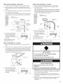
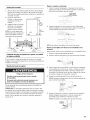
Tighten 90 ° elbow fitting to valve.
Electrical Shock Hazard
Electrically ground dishwasher.
Connect ground wire to green ground connector
in terminal box.
Do not use an extension cord.
Failure to follow these instructions can result in
death, fire, or electrical shock.
4. Form bare ground wire into a U-shaped hook. Wrap ground
wire hook clockwise around ground connector and under the
washer.
Be sure rubber washer is properly seated in fitting. Slide the _"
fitting up to the valve and hand tighten to avoid unintentional
cross-threading. Hand tighten until the coupling is tight. Using
pliers, check the tightness of the coupling. An additional 1/4to
1/2turn may be required to seal the rubber gasket.
NOTE: Do not overtighten. Damage to the coupling can result.
2. Check for leaks.
Place paper towel under 90 ° elbow fitting. Turn on water
supply and check for leaks. If leak occurs, repeat previous step.
13

2.
3.
4.
5.
To help minimize vibration,
route drain hose to avoid
contact with motor, door
springs, water line, cabinet,
flooring or the edge of the
hole where it passes
through the cabinet.
Do not remove drain loop
from side of dishwasher.
Place pan under end of
drain hose. Pan will collect
any water in drain hose.
-- _ Drain / I
Place the smaller drain hose clamp onto the small end of the
drain hose.
Hose clamp
Y
Push the drain hose into the connector up to the stop on the
drain hose.
Connector Stop
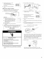
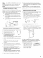
Tip Over Hazard
Do not use dishwasher until completely installed.
Do not push down on open door,
Doing so can resut in serious injury or cuts.
1. If you have not already done so, open dishwasher door and
place towel over pump assembly and spray arm of dishwasher.
This will keep screws from falling into pump area if you
unintentionally drop them when securing dishwasher to
countertop.
2. Check that dishwasher is still level and centered side to side in
the opening.
3. Secure dishwasher to countertop or sides of cabinet with two,
#10 x 1/2" Phillips-head screws. The dishwasher must be secured
to keep it from tipping when door is opened.
6°
Use pliers to open clamp and slide clamp onto connector
between stops on connector as shown.
Hose clamp
Stops
4.
5.
6°
Z
8.
Screw to countertop
Screw to
side cabinet i
Open door about 3" (7.6 cm) and check that space between
inner door and tub is equal on both sides. If spacing is not
equal, loosen bracket screws and shift tub. Tighten bracket
screws.
If using a countertop attachment to secure dishwasher, check
that top of door does not contact screws, brackets, or
countertop. If it does, dishwasher must be lowered and re-
leveled.
If securing with a side attachment, check that sides of door do
not rub against the screw heads. If they do, dishwasher must be
re-centered.
Remove towel from dishwasher.
Reinstall the lower dish rack.
14

Directwire method:
Complete installation
1.
2.
Check that grounding clip is attached to the lower panel.
Place the lower panel behind the access panel. Some models
have insulation on the access panel which must fall behind the
insulation on the lower panel.
Grounding
clip
3. Hold the two panels together and place them against
dishwasher leg.
4. Reinstall the screws through the holes in the access panel and
the slots in the lower panel. Install right side screw first.
J
_z
5. Check that the lower edge of the lower panel contacts the
floor.
6. Tighten the screws.
Electrical Shock Hazard
Electrically ground dishwasher.
Connect ground wire to green ground connector
in terminal box.
Do not use an extension cord.
Failure to follow these instructions can result in
death, fire, or electrical shock.
Power supply cord method:
Electrical Shock Hazard
Plug into a grounded 3 prong outlet.
Do not remove ground prong.
Do not use an adapter.
Do not use an extension cord.
Failure to follow these instructions can result
in death, fire, or electrical shock.
7. Reconnect power or plug in dishwasher.
Check operation
1. Read the Use and Care Guide that came with your dishwasher.
2. Check that all parts have been installed and no steps were
skipped.
3. Check that you have all the tools you used.
4. Start dishwasher and allow it to complete the shortest wash
cycle. After the first 2 minutes, unlatch door, wait 5 seconds,
then open door.
5. Check to see that there is water in the bottom of the dishwasher
tub. Check that dishwasher is working properly.
6. If not, disconnect power or unplug dishwasher and see "If
dishwasher does not operate" section.
If dishwasher does not operate
First try the solutions suggested here to possibly avoid the cost of a
service call.
• Has the circuit breaker tripped or the house fuse blown?
• Is the door closed tightly and latched?
• Has the cycle been set correctly to start the dishwasher?
• Is the water turned on?
If none of these work, call 1-800-4MY-HOME.
15

INDICE
SEGURIDAD DE LA LAVAVAJILLAS ............................................ 16
REQUISITOS DE INSTALACION .................................................. 17
Herramientas y piezas .......................................................................... 17
Requisitos de ubicaci6n ........................................................................ 17
Requisitos de desag0e .......................................................................... 19
Requisitos del suministro de agua ...................................................... 19
Requisitos el&ctricos .............................................................................. 19
INSTRUCCIONES DE INSTALACION .......................................... 20
Prepare la abertura del armario usando las
conexiones de servicio existentes ....................................................... 20
Prepare la abertura del armario donde no existen
conexiones de servicio .......................................................................... 21
Prepare la lavavajillas ......................................................................... 23
Conexi6n el&ctrica ................................................................................ 26
Conexi6n al suministro de agua ......................................................... 28
Conexi6n al desag0e ............................................................................ 28
Asegure la lavavajillas en la abertura del armario ....................... 29
SEGURIDAD DE LA LAVAVAJILLAS
Su seguridad y la seguridad de los demos es muy importante.
Hemos incluido muchos mensajes importantes de seguridad en este manual yen su electrodomestico. Lea y obedezca siempre
todos los mensajes de segurJdad.
Este es el sfmbolo de advertencia de seguridad.
Este simbolo le llama la atenci6n sobre peligros potenciales que pueden ocasionar la muerte o una lesi6n a
usted y a los demas.
Todos los mensajes de seguridad in:fina continuaci6n del sfmbolo de advertencia de seguridad y de la palabra
"PELIGRO" o "ADVERTENCIA". Estas palabras significan:
Si no sigue las instrucciones de inmediato, usted puede
morir o sufrir una lesi6n grave.
Si no sigue las instrucciones, usted puede morir o sufrir
una lesion grave.
Todos los mensajes de seguridad le diran el peligro potencial, le diran c6mo reducir las posibilidades de sufrir una lesi6n y Io que
puede suceder si no se siguen las instrucciones.
Peligro de Vuelco
No use la lavavajillas antes de estar cornpletamente
instalada.
No se apoye en la puerta abierta,
No seguir estas instrueeiones puede oeasionar heridas
serias o cortaduras.
Usted necesita=
• Abrir lentamente la puerta de la lavavajillas mientras alguien
sujeta la parte trasera de la lavavajillas. Quite los materiales
de env_o, la manguera de desag0e y la canasta inferior. Cierre
la puerta de la lavavajillas hasta que quede asegurada.
Cumplir con todos los c6digos y reglamentos vigentes.
Instalar la lavavajillas segGn se especifica en estas
instrucciones.
La instalaci6n debe ser hecha por un t&cnico de servicio
calificado. La lavavajillas debe instalarse de acuerdo con
todos los c6digos y reglamentos el&ctricos y de plomer_a
nacionales y locales.
16

REQUISITOSDE INSTALACION
Me_H_e_ _s_sy p zs:_
Re6na las herramientas y piezas necesarias antes de comenzar la
instalaci6n.
Todas las instalaciones
Herramientas necesarias: •
• Pinzas •
• Destornillador Phillips •
• Llaves de tuercas o •
casquillos hexagonales de •
5_6" y 1/4" •
• Cinta de medir o regla
• Llave ajustable de 10" que
se abra a 11/8" (2,9 cm)
• Destornillador de punta
plana
• Cuchillo de uso general
• 2 conectores de empalme
retorcido para alambre
que tengan el tama_o
adecuado para conectar el
cableado de su hogar al
cableado calibre 16 de la
lavavajillas
Adem6s, para nuevas instalaciones
Herramientas necesarias:
• Taladro inal6mbrico con •
brocas de sierra
perforadora de 1/2", 3/4" y
11/2"
• Cortatubos peque_o •
• Pelacables
• Abrazadera tipo tornillo de
11/2'' a 2" si se ha de
conectar al tubo de
desperdicios.
Nivel peque_o
Linterna
Recipiente poco profundo
Llave ajustable de 5/8"
Toalla de ba_o
Bloque de madera
Piezas necesarias:
• Cu_as (si se instala con un
piso armado)
• Conector a compresi6n de
3/8" x conector de
manguera de 3/4". P6ngase
en contacto con la tienda
local de Sears para
comprar el Juego N °
11000.
Piezas necesarias:
Tuber_a de cobre (se
recomienda de 3/8") o Ifnea
de Ilenado flexible de
acero inoxidable
Conector de abrazadera o
conector de conductos que
quepa en un orificio de 7/8"
(2,2 cm) de di6metro
Piezas provistas
A. 2 abrazaderas para la manguera de desag0e: 1 grande y 1
peque_a
B. 2 tornillos Phillips No. 10 x 1/2"
C. Manguera de desagge
D. 2 soportes de montaje para la parte inferior del mostrador
E. 2 soportes de montaje (superior) para el mostrador
C D
No instale tuberias de agua o desagOe o cables el&ctricos donde
puedan interferir o hacer contacto con el motor o las patas de la
lavavajillas.
El lugar donde se instalar6 la lavavajillas debe permitir un espacio
libre entre el motor y el piso. El motor no debe tocar el piso.
No instale la lavavajillas sobre piso alfombrado.
Proteja la lavavajillas y las Ifneas de agua que van a la lavavajillas
contra el congelamiento. La garanfia no cubre da_os por
congelaci6n.
Puede obtener un juego de panel lateral de su vendedor para
instalar su lavavajillas en el extremo del armario.
Su distribuidor tiene un accesorio que funciona como barrera
contra la humedad (Pieza N ° 4396277) para ser instalado debajo
del mostrador. Este puede obtenerse tambi&n Ilamando al
1-800-4MY-HOME.
Revise el lugar donde instalar6 la lavavajillas. El lugar debe
proveer:
F6cil acceso a instalaciones de agua, electricidad y desagOe.
Facilidad para cargar y descargar la lavavajillas. Los rincones
deben tener un espacio libre mfnimo de 2" (5,1 cm) entre el
costado de la puerta de la lavavajillas y la pared o el armario.
Una abertura cuadrada para que la lavavajillas funcione y se
vea bien.
• Un armario delantero que sea perpendicular al piso.
• Piso nivelado. (Si el piso en la parte delantera de la abertura
no est6 nivelado con el piso en la parte trasera de la abertura,
puede usar cu_as para nivelar la lavavajillas.)
NOTA: Las cu_as deben adherirse con firmeza al piso para evitar
que se muevan cuando se est& usando la lavavajillas.
Siva a dejar la lavavajillas sin uso por cierto tiempo o en un lugar
donde pudiera congelarse, haga que un miembro del personal de
servicio autorizado la prepare para el invierno.
Aseg6rese de que la tuber[a, los cables el&ctricos y la manguera de
desagOe est_n en el 6rea sombreada que se muestra en la secci6n
"Dimensiones de corte'.
Consejo 6til: Si el piso de la abertura donde colocar6 la
lavavajillas no es parejo (por ejemplo: piso con Iosetas s61o
hasta cierta parte de la abertura), deber6 ser exacto para
tomar las medidas y nivelar la lavavajillas.
Aseg6rese de que todas las piezas est&n incluidas. Si no Io est6n,
Ilame al 1-800-4MY-HOME.
Vea la lista de piezas que viene por separado para ver qu&
accesorios est6n disponibles para su lavavajillas.
17

Dimensionesdelproducto
!l aislamiento de
%" (1,g cm)--J,-__ 251/,"(64,1cm)
pued I |
compnm_rse I _ 241/2"(62,2cm)
(no se usa en | I
todos los | I
modelos)
33%" (86cm)
m_n,cuando se
hayan quitado
las ruedas
21" (53,3 cm) =_
VISTA LATERAL
23%" (60,6 cm)
VISTA POSTERIOR
Dimensionesde corte
-3-
(6,4 cm)_
13/4"
x 24" (61 cm)_
f Todas las superficies __
deben estar libres de intrusiones
34"
(86,4 cm)
mJn.*
(4,4 cm)$ (10,8 cm)$
(5,1 cm) 10"
(25,4 cm)
area fibreS:
Corte orificios en el 6rea sombreada de los paredes del armario o
del piso, como se especifica a continuaci6n:
tuberia de agua - 1/2" (1,3 cm)
tuberia de desagOe - 11/2'' (3,8 cm)
cable directo - 3/4" (1,9 cm)
cable de suministro de energfa - 11/2'' (3,8 cm)
_Medidas tomadas desde el punto m6s bajo de la parte inferior
del mostrador. Pueden reducirse a 337/8'' (86 cm) quitando las
ruedas de la lavavajillas.
_Minimo, medidas tomadas desde el punto m6s angosto de la
abertura.
_Pueden inerementarse a 67/8'' (17_5cm) si la altura de la
abertura es de 341/2'' (87_6 cm) en su punto m6s bajo.
SAmbos lados
18

Utilice la nueva manguera de desagOe provista con su
lavavajillas. Si no fuera Io suficientemente larga, use una
manguera de desagOe nueva de una Iongitud m6xima de
12 pies (3,7 m) que cumpla con todos los est6ndares de prueba
vigentes de la AHAM/IAPMO, sea resistente al calory a los
detergentes y quepa en el conector de desagOe de 1" (2,5 cm)
de su lavavajillas.
Conecte la manguera de desagOe al tubo de desperdicios o al
recipiente de desechos sobre el sif6n de desagOe en las
instalaciones sanitarias de la casa y a un mfnimo de 20"
(50,8 cm) sobre el piso. Se recomienda que la manguera de
desagOe se enrolle en un lazo y se sujete con seguridad a la
parte inferior del mostrador o que se conecte a un espaciador
de aire.
Espaciador de aire
IL
Use un espaciador de aire si la manguera de desagOe est6
conectada a las instalaciones sanitarias de la casa a menos de
20" (50,8 cm) sobre el contrapiso o el piso.
Utilice accesorios de tubeHa de desagOe con di6metro interno
de 1/2" como mfnimo.
Req_}_sos de sum _ss_Hsde _xs£_
• Tuber_a de agua caliente con una presJ6n de agua de
20 a 120 Ib/pulg 2 (138 a 862 kPa).
• Agua a 120°F (49°C) en la lavavajillas.
• Tuber_a de cobre con 3/8" de di6metro exterior con accesorio de
compresi6n o Ifnea de Ilenado flexible de acero inoxidable con
cubierta trenzada (no se recomienda usar tubeHa pl6stica con
un mfnimo de 1/2").
• Un codo de 90 ° con roscas de tuber_a externas de 3/8" (N.P.T.)
en un extremo.
No suelde dentro de una distancia de 6" (15,2 cm) de la v61vula de
entrada de agua.
P6ngase en contacto con un electricista calificado.
Aseg6rese de que la instalaci6n el_ctrica sea adecuada y cumpla
con todos los c6digos y reglamentos nacionales y locales.
Usted debe tener:
• Un suministro el6ctrico de 120 voltios, 60 Hz, CA solamente,
de 15 6 20 amperios con fusible.
• Alambre de cobre solamente.
Recomendamos:
• Un fusible de retardo o un disyuntor.
• Un circuito separado.
Si est6 haciendo una conexi6n directa a la lavavajillas:
• Utilice cable de cobre flexible, blindado o con forro no
met61ico con alambre de puesta a tierra adecuado a los
requisitos de cableado de su hogar y que cumpla con los
c6digos y reglamentos de su Iocalidad.
Utilice el protector de cables provisto con la caja de empalmes
de su hogar o instale en la caja de empalmes un conector de
abrazadera aprobado por el UL/certificado por CSA en la
caja de empalmes de su hogar. Si usa un conducto para cables,
use un protector de cables aprobado por el UL/certificado por
CSA.
Si est6 conectando la lavavajillas con un cable de suministro de
enercjra:
• Utilice el Juego de cable de suministro de energfa (Pieza No.
4317824) que est6 marcado para ser usado con lavavajillas. El
juego contiene:
- Cable de suministro de energfa de Volex, Inc. en la lista de
UL, de 3 hilos de calibre 16 con un enchufe de 3 terminales
con conexi6n a tierra.
- Protector de cables Neer C-500 de 7/8".
- 3 conectores de alambre.
- Aro de refuerzo, pieza N ° 302797.
Siga las instrucciones del juego para instalar el cable de
suministro de energfa.
El cable de suministro de energfa debe enchufarse en un
contacto de conexi6n a tierra de tres terminales, ubicado en el
armario pr6ximo a la abertura de la lavavajillas. El contacto
debe estar conforme a todos los c6digos y ordenanzas locales.
19

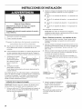
INSTRUCCIONES DE INSTALACION
Peligro de Choque EI6ctrico
Desconecte el surninistro de energfa en la caja de
fusibles o cortacircuitos antes de instalar
la lavavajilias.
No seguir esta instrucci6n puede ocasionar la muerte o
choque el6ctrico,
1. Desconecte el suministro de energfa.
2. Cierre el suministro de agua.
Siga los pasos en esta secci6n si est6 instalando la lavavajillas
en una abertura del armario con conexiones de servicio
existentes.
Si est6 instalando la lavavajillas en un espacio del armario que
no tiene conexiones, siga los pasos de la secci6n "Prepare la
abertura del armario donde no existen conexiones de servicio'.
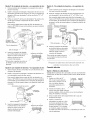
1. Verifique que la tuberfa
de agua Ilegue a la
parte frontal izquierda
de la abertura donde se
har6 la conexi6n de
agua.
2. Verifique que el cable
directo Ilegue a la parte
I
Cable directo
frontal derecha de la abertura del armario donde se har6 la
conexi6n el&ctrica.
Si la tuber[a de agua y el cable directo Ilegan Io suficientemente
lejos en la abertura, proceda a la siguiente secci6n "lnstalaci6n de
la manguera de desagOe'. Si no Ilegan Io suficientemente lejos,
siga los pasos de la secci6n "Prepare la abertura del armario
donde no existen conexiones de servicio'.
2. Conecte la manguera de desagOe al tubo de desperdicios o al
recipiente de desechos utilizando uno de los siguientes
m&todos.
• Opci6n 1: con recipiente de desechos - con espaciador de
aire
• Opci6n 2: sin recipiente de desechos - con espaciador de
aire
• Opci6n 3: con recipiente de desechos - sin espaciador de
aire*
• Opci6n 4: sin recipiente de desechos - sin espaciador de
aire*
*Se recomienda un espaciador de aire
Consejo 6til: Para reducir la vibraci6n de la manguera,
mantenga &sta lejos del piso y del borde del orificio por el que
aqu&lla pasa a trav&s del armario.
Opci6n 1, Recipiente de desechos - con espaciador de aire:
1. Quite el tap6n del disco removible. Corte el extremo de la
manguera de desagOe si es necesario (no corte la secci6n
ranurada).
2. Sujete la manguera de desagOe al espaciador de aire con una
abrazadera grande de tipo resorte. Si se cort6 la manguera de
desagOe, utilice una abrazadera* de tipo tornillo de lY2" a 2"
(3,8 a 5 cm).
3. Utilice un conector* de manguera de hule con abrazaderas*
de resorte o de tornillo para conectar el espaciador de aire a
la entrada del recipiente de desechos.
Esta conexi6n debe hacerse antes del sif6n de desagOe y al
menos a 20" (50,8 cm) por encima del piso en que se instalar6
la lavavajillas.
Conector de la
nanguera de hule Espaciador
de aire
Abrazadera
resorfe
Manguera de
desagiJe = carte aqui uera de
si es necesario, gue
Sif6n de desagiJe
Instalaci6n de la manguera de desagUe
IMPORTANTE: Siempre utilice una manguera de desagOe nueva,
aunque instale una lavavajillas nueva que reemplace a otra.
1. Perfore un orificio de 11/2'' (3,8 cm) de di6metro en la pared o el
piso del armario, en el lado de la abertura del armario que
est& m6s cerca del fregadero.
4. Inserte la manguera de desagOe en
el orificio hecho en el armario y
dirfjala al centro frontal de la
abertura donde se har6 la conexi6n
del desagOe.
*Estas partes se pueden encontrar en
las tiendas locales de art[culos de
plomerfa.
I I
Manguera de desagiJe
2O
Page is loading ...
Page is loading ...
Page is loading ...
Page is loading ...
Page is loading ...
Page is loading ...
Page is loading ...
Page is loading ...
Page is loading ...
Page is loading ...
Page is loading ...
Page is loading ...
Page is loading ...
Page is loading ...
Page is loading ...
Page is loading ...
Page is loading ...
Page is loading ...
Page is loading ...
Page is loading ...
Page is loading ...
Page is loading ...
Page is loading ...
Page is loading ...
Page is loading ...
Page is loading ...
Page is loading ...
Page is loading ...
-
 1
1
-
 2
2
-
 3
3
-
 4
4
-
 5
5
-
 6
6
-
 7
7
-
 8
8
-
 9
9
-
 10
10
-
 11
11
-
 12
12
-
 13
13
-
 14
14
-
 15
15
-
 16
16
-
 17
17
-
 18
18
-
 19
19
-
 20
20
-
 21
21
-
 22
22
-
 23
23
-
 24
24
-
 25
25
-
 26
26
-
 27
27
-
 28
28
-
 29
29
-
 30
30
-
 31
31
-
 32
32
-
 33
33
-
 34
34
-
 35
35
-
 36
36
-
 37
37
-
 38
38
-
 39
39
-
 40
40
-
 41
41
-
 42
42
-
 43
43
-
 44
44
-
 45
45
-
 46
46
-
 47
47
-
 48
48


Ask a question and I''ll find the answer in the document
Finding information in a document is now easier with AI
in other languages
Related papers
-
 Kenmore Elite 66513966K014 Installation guide
-
 Kenmore Elite 66513206K901 Installation guide
-
Kenmore 66516034400 Installation guide
-
Kenmore 66577972K703 Installation guide
-
Kenmore Elite 2214523N611 Installation guide
-
Kenmore Elite 66512779K311 Installation guide
-
Kenmore 66513683K600 Installation guide
-
Kenmore Elite 24'' Built-In Dishwasher - Bisque ENERGY STAR Installation guide
-
Kenmore Elite 66513799K600 Installation guide
-


Other documents
-
Haier HDBC100AFS Installation Instructions Manual
-
KitchenAid 8564554 User manual
-
Kenmore Elite 66513932K010 Installation guide
-
KitchenAid KUDT03FTWH1 Installation guide
-
KitchenAid KUDW02FRWH4 Installation guide
-
Kenmore Pro 66513173K706 Installation guide
-
-
Roper Dishwasher Undercounter Dishwasher User manual
-
Whirlpool Gold GU3100XTV User manual
-
Whirlpool WDF550SAAW Owner's manual