KitchenAid KVWB606HBS0 Owner's manual
- Category
- Cooker hoods
- Type
- Owner's manual
This manual is also suitable for

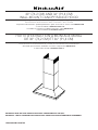
30” (76.2 CM) AND 36” (91.4 CM)
WALL-MOUNT CANOPY RANGE HOOD
Installation Instructions and Use and Care Guide
For questions about features, operation/performance, parts, accessories or service, call: 1-800-422-1230
or visit our website at www.kitchenaid.com
In Canada, for assistance, installation and service, call: 1-800-807-6777
or visit our website at www.kitchenaid.ca
HOTTE D’EXTRACTION À MONTAGE MURAL
DE 30" (76,2 CM) ET 36" (91,4 CM)
Instructions d’installation et Guide d’utilisation et d’entretien
Au Canada, pour assistance, installation ou service, composez le 1-800-807-6777
ou visitez notre site web à www.kitchenaid.ca
IMPORTANT: READ AND SAVE THESE INSTRUCTIONS. FOR RESIDENTIAL USE ONLY.
IMPORTANT : LIRE ET CONSERVER CES INSTRUCTIONS. POUR UTILISATION RÉSIDENTIELLE UNIQUEMENT.
LIB0143609/W11230974B

2
TABLE OF CONTENTS
RANGE HOOD SAFETY .................................................................3
INSTALLATION REQUIREMENTS ................................................. 5
Tools and Parts ............................................................................. 5
Location Requirements ................................................................5
Venting Requirements ..................................................................6
Electrical Requirements ...............................................................7
INSTALLATION INSTRUCTIONS ................................................... 8
Prepare Location ..........................................................................8
Install Range Hood ....................................................................... 9
Connect Vent System ..................................................................9
Make Electrical Connection .......................................................10
Install Vent Covers ......................................................................11
Complete Installation .................................................................11
RANGE HOOD USE ......................................................................11
Controls and Features ................................................................ 11
RANGE HOOD CARE ...................................................................12
Cleaning .....................................................................................12
WIRING DIAGRAM .......................................................................14
WHIRLPOOL SERVICE ................................................................15
TABLE DES MATIÈRES
SÉCURITÉ DE LA HOTTE DE CUISINIÈRE ...............................17
EXIGENCES D’INSTALLATION ...................................................19
Outils et pièces ...........................................................................19
Exigences d’emplacement .........................................................19
Exigences concernant l’évacuation ...........................................20
Spécications électriques ..........................................................21
INSTRUCTIONS D’INSTALLATION .............................................22
Préparation de l’emplacement ...................................................22
Installation de la hotte ................................................................23
Raccordement du circuit d’évacuation ...................................... 23
Raccordement électrique ...........................................................24
Installation des cache-conduits .................................................25
Achever l’installation ..................................................................25
UTILISATION DE LA HOTTE .......................................................26
Commandes et caractéristiques ................................................26
ENTRETIEN DE LA HOTTE .........................................................27
Nettoyage ...................................................................................27
SCHÉMA DE CÂBLAGE ...............................................................29
SERVICE WHIRLPOOL ................................................................30

3
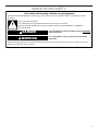
RANGE HOOD SAFETY
You can be killed or seriously injured if you don't immediately
You
can be killed or seriously injured if you don't
follow
All safety messages will tell you what the potential hazard is, tell you how to reduce the chance of injury, and tell you what can
happen if the instructions are not followed.
Your safety and the safety of others are very important.
We have provided many important safety messages in this manual and on your appliance. Always read and obey all safety
messages.
This is the safety alert symbol.
This symbol alerts you to potential hazards that can kill or hurt you and others.
All safety messages will follow the safety alert symbol and either the word “DANGER” or “WARNING.”
These words mean:
follow instructions.
instructions.
DANGER
WARNING

4
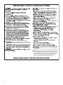
IMPORTANT SAFETY INSTRUCTIONS
READ
AND
SAVE
THESE
INSTRUCTIONS
For General Ventilating Use Only. Do Not Use
To Exhaust Hazardous Or Explosive Materials And Vapors.
This appliance is not intended for use by people (including
children) whose physical, sensory or mental capacities are
different or impaired or who lack the necessary experience
or knowledge/expertise to do so, unless such persons are
supervised or are trained to operate the appliance by a
person who accepts responsibility for their safety.
To Reduce The Risk Of Fire Or Electric
Shock, Do Not Use This Fan With Any Solid-State Speed
Control Device.
Ducted fans must always be vented to the outdoors.

5
INSTALLATION REQUIREMENTS
Tools and Parts
Gather the required tools and parts before starting installation.
Read and follow the instructions provided with any tools listed
here.
Tools Needed
■ Level
■ Drill with 1¼" (3.0 cm), 3/8" (9.5 mm), and 5/16" (7.9 mm)
drill bits
■ Pencil
■ Wire stripper or utility knife
■ Tape measure or ruler
■ Pliers
■ Caulking gun and weatherproof caulking compound
■ Vent clamps
■ Jigsaw or keyhole saw
■ Flat-blade screwdriver
■ Metal snips
■ Phillips screwdriver
Parts Needed
■ Home power supply cable
■ 1/2" (13 mm) UL listed or CSA approved strain relief
■ Three UL Listed wire connectors
For Vented Installations, You Will Also Need:
■ One wall or roof cap
■ Metal vent system
For Non-Vented (Recirculating) Installations, You Will
Also Need:
■ Recirculation Kit Part Number W10692908 for non-vented
(recirculating) installations only. See the “Assistance or
Service” section to order.
■ 6" (15.2 cm) diameter round metal vent duct—length
required is determined by ceiling height.
Parts Supplied
Remove parts from packages. Check that all parts are included.
■ Hood canopy assembly with ventilator and LED and halogen
lights installed
■ Vent transition with back draft dampers installed
■ Metal grease lter(s)—depending on model and size
■ Vent cover support bracket
■ Mounting template
■ Two-piece vent cover
■ Four 4.2 x 8 screws
■ Six 5 x 45 mm mounting screws
■ Two D6.4 x 18 mm washers
■ Two 8 x 40 mm wall anchors
■ Four10 x 60 mm wall anchors
■ Four 5.4 x 75 mm screws (for 10 x 60 mm wall anchors)
■ Two 3.5 x 9.5 mm sheet metal screws
■ T10
®
TORX
®†
adapter
Location Requirements
IMPORTANT: Observe all governing codes and ordinances.
Have a qualied technician install the range hood. It is the
installer’s responsibility to comply with installation clearances
specied on the model/serial/rating plate. The model/serial/
rating plate is located behind the left lter on the rear wall of the
vent hood.
Canopy hood location should be away from strong draft areas,
such as windows, doors and strong heating vents.
Cabinet opening dimensions that are shown must be used.
Given dimensions provide minimum clearance.
This range hood is recommended for use with cooktops with a
maximum total rating of 65,000 BTUs or less.
Grounded electrical outlet is required. See the “Electrical
Requirements” section.
The canopy hood is factory-set for venting through the roof
or wall. For non-vented (recirculating) installation see “For
nonvented (recirculating) installation only” in the “Connect Vent
System” section. Recirculation Kit Part Number W10692908 is
available from your dealer or an authorized parts distributor.
All openings in ceiling and wall where canopy hood will be
installed must be sealed.
For Mobile Home Installations
The installation of this range hood must conform to the
Manufactured Home Construction Safety Standards, Title 24
CFR, Part 328 (formerly the Federal Standard for Mobile Home
Construction and Safety, Title 24, HUD, Part 280) or when such
standard is not applicable, the standard for Manufactured Home
Installation 1982 (Manufactured Home Sites, Communities and
Setups) ANSI A225.1/NFPA 501A, or latest edition, or with local
codes.
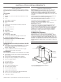
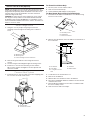
Product Dimensions
*For non-vented (recirculating) installations
**For vented installations
10¾" (27.3 cm)
13³⁄₁₆" (33.5 cm)
*28⁷⁄₈" (73.4 cm) min.
43³⁄₁₆" (109.7 cm) max.
**25¹⁄₄" (64.1 cm) min.
39¹¹⁄₃₂
" (98.4 cm) max.
24"
(60.8 cm)
5"
(12.7 cm)
19¹¹⁄₁₆" (50.0 cm)
30" (76.2 cm)
36" (91.4 cm)
†
®
TORX and T10
®
are registered trademarks of Acument Intellectual Properties, LLC.

6
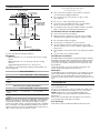
Cabinet Dimensions
*For non-vented (recirculating) installations
IMPORTANT:
Minimum distance “X”: 24" (61.0 cm) from electric cooking
surface.
Minimum distance “X”: 27" (68.6 cm) from gas cooking
surfaces.
Suggested maximum distance “X”: 36" (91.4 cm)
The chimneys can be adjusted for different ceiling heights. See
the following chart.
Vented Installations
Min. ceiling height Max. ceiling height
Electric cooking
surface
7' 1" (2.16 m) 9' 3" (2.82 m)
Gas cooking
surface
7' 4" (2.23 m) 9' 3" (2.82 m)
Non-vented (recirculating) Installations
Min. ceiling height Max. ceiling height
Electric cooking
surface
7' 5" (2.23 m) 9' 7" (2.9 m)
Gas cooking
surface
7' 8" (2.33 m) 9' 7" (2.9 m)
NOTE: The range hood chimneys are adjustable and designed to
meet varying ceiling or soft heights depending on the distance
“X” between the bottom of the range hood and the cooking
surface. For higher ceilings, a Chimney Extension Kit is available
from your dealer or an authorized parts distributor. The chimney
extension replaces the chimney shipped with the range hood. To
order, see the “Assistance or Service” section.
Venting Requirements
(Vented Models Only)
■ Vent system must terminate to the outdoors except for
non-vented (recirculating) installations.
■ Do not terminate the vent system in an attic or other
enclosed area.
■ Do not use 4" (10.2 cm) laundry-type wall caps.
■ Use metal vent only. Rigid metal vent is recommended.
Plastic or metal foil vent is not recommended.
■ The length of vent system and number of elbows should be
kept to a minimum to provide efcient performance.
For the Most Efcient and Quiet Operation:
■ Use no more than three 90° elbows.
■ Make sure there is a minimum of 24" (61.0 cm) of straight
vent between the elbows if more than one elbow is used.
■ Do not install two elbows together.
■ Use clamps to seal all joints in the vent system.
■ The vent system must have a damper. If the roof or wall
cap has a damper, do not use the damper supplied with the
range hood.
■ Use caulking to seal exterior wall or roof opening around the
cap.
■ The size of the vent should be uniform.
Cold Weather Installations
An additional back draft damper should be installed to minimize
backward cold air ow and a thermal break should be installed
to minimize conduction of outside temperatures as part of the
vent system. The damper should be on the cold air side of the
thermal break.
The break should be as close as possible to where the vent
system enters the heated portion of the house.
Makeup Air
Local building codes may require the use of makeup air systems
when using ventilation systems greater than specied CFM of
air movement. The specied CFM varies from locale to locale.
Consult your HVAC professional for specic requirements in your
area.
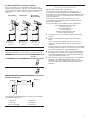
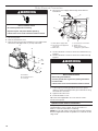
Venting Methods
This canopy range hood is factory set for venting through the
roof or through the wall.
A 6" (15.2 cm) round vent system is needed for installation (not
included). The hood exhaust opening is 6" (15.2 cm) round.
NOTE: Flexible vent is not recommended. Flexible vent
creates back pressure and air turbulence that greatly reduce
performance.
Vent system can terminate either through the roof or wall. To
vent through a wall, a 90° elbow is needed.
Rear Discharge
A 90° elbow may be installed immediately above the hood.
10" (25.4 cm) min.
13" (33.0 cm) max.
2" (5.1 cm) min.
9" (22.9 cm) min.*
Centerline
Side
cabinet
Side
cabinet
Vent and po
wer
supply cable
entry location
17" (43.2 cm)*
30" (76.2 cm) or
36" (91.4 cm)
“X”
bottom of
canopy
to cooking
surface
10" (25.4 cm) min.
13" (33.0 cm) max.
Cooking surface

7
For Non-Vented (Recirculating) Installations
If it is not possible to vent cooking fumes and vapors to the
outside, the hood can be used in the non-vented (recirculating)
version using a Recirculation Kit (which includes charcoal lters
and a deector). To order, see the “Assistance or Service”
section.
Calculating Vent System Length
To calculate the length of the system you need, add the
equivalent feet (meters) for each vent piece used in the system.
Vent Piece 6" (15.2 cm)
Round
45° elbow 2.5 ft (0.8 m)
90° elbow 5.0 ft (1.5 m)
Maximum equivalent vent length is 35 ft (10.7 m).
Example Vent System
The following example falls within the maximum recommended
vent length of 35 ft (10.7 m).
1 - 90° elbow = 5.0 ft (1.5 m)
1 - wall cap = 0.0 ft (0.0 m)
8 ft (2.4 m) straight = 8.0 ft (2.4 m)
Length of system = 13.0 ft (3.9 m)
Electrical Requirements
Observe all governing codes and ordinances.
Ensure that the electrical installation is adequate and in
conformance with National Electrical Code, ANSI/NFPA 70
(latest edition), or CSA Standards C22.1-94, Canadian Electrical
Code, Part 1 and C22.2 No. 0-M91 (latest edition) and all local
codes and ordinances.
If codes permit and a separate ground wire is used, it is
recommended that a qualied electrician determine that the
ground path is adequate.
A copy of the above code standards can be obtained from:
National Fire Protection Association
1 Batterymarch Park
Quincy, MA 02169-7471
CSA International
8501 East Pleasant Valley Road
Cleveland, OH 44131-5575
■ A 120 V, 60 Hz, AC only, 15-amp, fused electrical circuit is
required.
■ If the house has aluminum wiring, follow the procedure
below:
Connect the aluminum wiring using special connectors
and/or tools designed and UL listed for joining copper to
aluminum.
Follow the electrical connector manufacturer’s recommended
procedure. Aluminum/copper connection must conform with
local codes and industry accepted wiring practices.
■ Wire sizes and connections must conform with the rating of
the appliance as specied on the model/serial/rating plate.
The model/serial/rating plate is located behind the left lter
on the rear wall of the range hood.
■ Wire sizes must conform to the requirements of the National
Electrical Code, ANSI/NFPA 70 (latest edition), or CSA
Standards C22. 1-94, Canadian Electrical Code, Part 1 and
C22.2 No. 0-M91 (latest edition) and all local codes and
ordinances.
A
A
B
B
B
A
Roof Venting Wall Venting Non-Vented
(Recirculating)
A. Roof cap
B. 6" (15.2 cm)
round vent
A. Wall cap
B. 6" (15.2 cm)
round vent
A. Diverter
B. 6" (15.2 cm)
round vent
90 elbo
w
6 ft (1.8 m)
2 ft
(0.6 m)
Wall cap

8
INSTALLATION INSTRUCTIONS
Prepare Location
■ It is recommended that the vent system be installed before
hood is installed.
■ Before making cutouts, make sure there is proper clearance
within the ceiling or wall for exhaust vent.
■ Check your ceiling height and the hood height maximum
before you select your hood.
1. Disconnect power.
2. Determine which venting method to use: roof, wall, or
non-vented.
3. Select a at surface for assembling the range hood. Place
covering over that surface.
4. Using two or more people, lift range hood onto covered
surface.
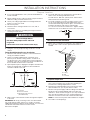
Range Hood Mounting Screws Installation
1. Determine and mark the centerline on the wall where the
canopy hood will be installed.
2. Select a mounting height between a minimum of 24"
(61.0cm) for an electric cooking surface, a minimum of
27" (68.6cm) for a gas cooking surface, and a suggested
maximum of 36" (91.4 cm) above the range to the bottom of
the hood. Mark a reference line on the wall.
3. Tape template in place, aligning the template centerline and
bottom of template with hood bottom line and with the
centerline marked on the wall.
4. Mark centers of the fastener locations through the template
to the wall.
IMPORTANT: All canopy mounting screws must be installed
into wood where possible. If there is no wood to screw into,
additional wall framing supports may be required, or use the four
10 x 60 mm wall anchors and 5.4 x 75 mm screws.
Remove the template.
5. For wood, drill 3/16" (4.8 mm) pilot holes at all locations
where screws are being installed into wood.
For wall anchors, drill 7/16" (10 mm) holes at all locations
where wall anchors are being used.
6. For wood, install two 5 x 45 mm mounting screws. Leave a
1/4" (6.4 mm) gap between the wall and the back of the
screw head to slide range hood into place. For wall anchors,
install the 10 x 60 mm wall anchors and install the
5.4x75mm screws into the wall anchors. Tighten until the
wall anchors are secure. Back the screws out 1/4" (6.4 mm).
Vent Cover Bracket Installation
1. Attach vent cover bracket to wall ush to the ceiling using
two 5 x 45 mm screws. Use the optional wall anchors if
needed.
Complete Preparation
1. Determine and make all necessary cuts in the wall for the
vent system. Install the vent system before installing the
hood. See the “Venting Requirements” section.
2. Determine the required height for the home power supply
cable and drill a 1¼" (3.2 cm) hole at this location.
3. Run the home power supply cable according to the National
Electrical Code or CSA Standards and local codes and
ordinances. There must be enough 1/2" (13 mm) conduit and
wires from the fused disconnect (or circuit breaker) box to
make the connection in the hood’s electrical terminal box.
NOTE: Do not reconnect power until installation is complete.
4. Use caulk to seal all openings.
WARNING
Excessive Weight Hazard
Use two or more people to move and install
range hood.
Failure to do so can result in back or other injury.
Vertical Centerline
C
L
LLAW RAER
ETALPMET GNITNUOM
EGDE MOTTOB NGILA
ENIL LICNEP HTIW
MOTTOB GNITACIDNI
DOOH EHT FO
thgieH noitallatsnI
TROPPUS LLAW RAER RO SDUTS HGUORHT SELOH TOLIP "61/3 )OWT( 2 LLIRD
eniL latnoziroH
A
C
B
A. Centerline
B. Fastener locations
C. Mounting height reference
(hood bottom line)
¹⁄₄
"
(6.4 mm)
A
C
B
A. Ceiling
B. Wall
C. Centerline

9
Install In-Line Smart Kit (Optional)
NOTE: Your range hood can work with either an internal or an
in-line (external) blower motor system. An optional In-Line Smart
Kit (purchased separately) allows the blower motor that comes
with this range hood to be installed in a location other than
inside the range hood cavity.
CAUTION: To reduce the risk of re and electric shock, install
this range hood only with the In-Line Smart Kit manufactured
by Whirlpool, part number W10692945. For installation see the
In-Line Smart Kit installation instructions. See the “Assistance or
Service” section to order.
Install Range Hood
1. Using two or more people, hang range hood on two
mounting screws through the mounting slots on back of
hood.
2. Remove the grease lter. See the “Range Hood Care”
section.
3. Level the range hood and tighten upper mounting screws.
4. Install two 5 x 45 mm lower mounting screws and two
D6.4x18mm washers and tighten. Use the optional wall
anchors if needed.
Connect Vent System
1. Install transition on top of hood (if removed for shipping) with
two 3.5 x 9.5 mm sheet metal screws.
For Vented Installations Only:
1. Fit vent system over the exhaust outlet.
2. Seal connection with clamps.
3. Check that back draft dampers work properly.
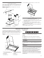
For Non-Vented (Recirculating) Installation Only:
1. Assemble the air deector with the duct cover bracket using
four 4.2 x 8 mm screws.
2. Measure from the bottom of the air deector to the bottom of
the hood outlet.
3. Cut the duct to the measured size “X.”
4. Remove the air deector.
5. Slide the duct onto the bottom of the air deector.
6. Place the assembled air deector and duct over the exhaust
outlet from the hood.
7. Reassemble the air deector to the duct cover bracket with
the four assembly screws.
8. Seal connections with vent clamps.
A
B
C
A. Mounting screws
B. Mounting slots
C. Lower mounting screws and washers
B
A
A. Vent transition
B. 3.5 x 9.5 mm screws
A
B
C
A. Assembly screws
B. Air deector
C. Duct cover bracket
X
A
C
D
B
E
A. Air deector
B. Vent clamp
C. X = length to cut vent
duct
D. Vent duct
E. Exhaust outlet

10
Make Electrical Connection
1. Disconnect power.
2. Remove terminal box cover.
3. Remove the knockout in the terminal box cover and install a
UL listed or CSA approved 1/2" (13 mm) strain relief.
4. Run home power supply cable through strain relief into
terminal box.
5. Use UL Listed wire connectors and connect black wires (C)
together.
6. Use UL Listed wire connectors and connect white wires (E)
together.
7. Connect green (or bare) ground wire from home power
supply to yellow-green ground wire (F) in terminal box using
UL Listed wire connectors.
8. Tighten strain relief screw.
9. Install terminal box cover.
10. Check that all light bulbs are secure in their sockets.
11. Reconnect power.
Optional Power Cord Kit Installations
For optional power cord kit installations, follow the instructions
supplied with the power cord kit. See the “Assistance or
Service” section for information on ordering.
NOTE: Use only with range hood cord connection kits that have
been investigated and found acceptable for use with this model
range hood.
WARNING
Electrical Shock Hazard
Disconnect power before servicing.
Replace all parts and panels before operating.
Failure to do so can result in death or electrical shock.
A
B
C
C
C
C
A. Knockout
B. Terminal box cover
C. Screws (7)
A
B
C
D
E
F
A. Home power supply cable
B. UL Listed or CSA approved
strain relief
C. Black wires
D. UL Listed wire connectors
E. White wires
F. Green (or bare) and
yellowgreen ground wires
WARNING
Electrical Shock Hazard
Electrically ground blower.
Connect ground wire to green and yellow ground wire
in terminal box.
Failure to do so can result in death or electrical shock.

11
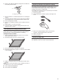
Install Vent Covers
When using both upper and lower vent covers, push lower cover
down onto hood and lift upper cover to ceiling and install with
two 4.2 x 8 mm screws.
NOTE: For vented installations the upper vent cover may be
reversed to hide slots.
Secure the bottom of the duct with two 4.2 x 8 mm screws.
Complete Installation
1. For non-vented (recirculating) installations only, install
charcoal lters over grille on blower housing. See the “Range
Hood Care” section.
2. Install metal lters. See the “Range Hood Care” section.
3. Check the operation of the range hood blower and light. See
the “Range Hood Use” section.
NOTE: To get the most efcient use from your new range hood,
read the “Range Hood Use” section.
RANGE HOOD USE
The range hood is designed to remove smoke, cooking vapors
and odors from the cooktop area. For best results, start the hood
before cooking and allow it to operate several minutes after
the cooking is complete to clear all smoke and odors from the
kitchen.
The range hood controls are located on the front side of the
canopy.
Control Panel
Controls and Features
NOTES:
■ To activate the controls, press and release the desired
button.
■ The control feature touch will be lit when a control feature is
turned on.
Sleep Mode
The range hood automatically enters Sleep Mode when not in
use. After 10 minutes of no range hood activity, all of the control
button lights will turn off. To deactivate Sleep Mode, press any
button.
Auto Sense
Auto Sense allows the range hood fan to turn on automatically
when it senses heat higher than its allowable temperature limit.
When Auto Sense is on, the fan speed will increase or decrease
based on the temperature Auto Sense is measuring.
Auto Sense can be manually increased by pressing a higher fan
speed. The fan will run at the selected speed for 10 minutes
before returning to the speed selected for Auto Sense.
If Auto Sense is on, the Auto button light will turn off and go into
Sleep Mode when the vent hood is not in use. If the vent hood
is turned on by the consumer or by Auto Sense, the Auto button
light will turn on.
A
B
C
D
A. Upper vent cover
B. Lower vent cover
C. 4.2 x 8 mm screws
D. Bracket
A
B
C
D
E
F
G
H
A. Louver holes (non-vented
[recirculating] installations only)
B. Duct covers
C. LED lights (2)
D. Perimetric cover
E. Metal grease lters (located
behind the perimetric cover)
F. Canopy
G. Halogen light
H. Control panel

12
To Set Auto Sense:
Press AUTO.
To Select Auto Sense Cooktop Type:
NOTE: The range hood is factory-set for the gas cooktop
mode.
1. Press and hold AUTO for 5 seconds to switch between the
gas cooktop and electric cooktop modes.
2. The Auto button light will ash ve times when the range
hood is changed to the electric cooktop mode. Auto Sense
is now set to work with electric cooktops and ranges.
3. The Auto button light will ash three times when the range
hood is changed to the gas cooktop mode. Auto Sense is
now set to work with gas cooktops and ranges.
4. Changing the cooktop type will change the temperature limit
for Auto Sense to turn on. When the range hood senses a
high enough temperature, the fan will start automatically.
When the temperature drops below the set temperature limit,
the fan will stop automatically. The Auto button light will turn
off after the range hood enters Sleep Mode, but Auto Sense
is still active.
To Deactivate Auto Sense:
1. If the Auto button is lit, press AUTO once to deactivate Auto
Sense. The Auto button light will turn off.
2. If Auto Sense is in Sleep Mode, press AUTO once to
deactivate Sleep Mode and turn the Auto button light on.
Press AUTO again to deactivate Auto Sense and turn off the
Auto button light.
3. Auto Sense will automatically turn off after 2 hours of no
activation of the Auto Sense system. To reset Auto Sense,
press AUTO.
Manual Vent Functions
Fan Speeds
Low Press LOW to turn the fan on at Low speed.
Med Press MED to turn the fan on at Medium speed.
Hi Press HI to turn the fan on at High speed.
Boost Press BOOST to turn the fan on at the highest
speed. Boost will automatically turn off after 10
minutes and the fan will switch to High speed.
Timer
The range hood can be set to automatically turn off after 15
minutes.
1. Press and hold the desired fan speed button for 2 seconds.
The fan will run on the chosen speed for 15 minutes, and
the fan speed button light will ash continuously. After 15
minutes, the fan will turn off automatically.
2. Press the desired fan speed button again while the fan timer
is running to cancel the fan timer.
NOTE: Changing the fan speed or turning Auto Sense on will
also cancel the 15-minute timer.
Light
The range hood has both task and ambient lighting.
To operate the lights:
1. Touch LIGHT ON/OFF once, and the LED task lights will turn
on.
2. Touch LIGHT ON/OFF again, and the LED task lights will turn
off. The ambient lights will turn on.
3. Touch LIGHT ON/OFF a third time, and the ambient lights will
turn off.
NOTE: To turn both the task and ambient lights on at the
same time, touch and hold LIGHT ON/OFF for 2 seconds.
Touch LIGHT ON/OFF again to turn the task and ambient
lights off.
RANGE HOOD CARE
Cleaning
IMPORTANT: Clean the hood and grease lters frequently
according to the following instructions. Replace grease lters
before operating hood.
Exterior Surfaces:
To avoid damage to the exterior surface, do not use steel wool
or soap-lled scouring pads.
Always wipe dry to avoid water marks.
Cleaning Method:
■ Liquid detergent soap and water or all-purpose cleanser.
■ Wipe with a damp soft cloth or nonabrasive sponge, and
then rinse with clean water and wipe dry.
Metal Grease Filter
1. Open the stainless steel panel. Grasp panel at the front
corners, and then pull down to disengage the two catch pins
from the spring catches. The panel is attached at the rear
and will rotate down.
C
D
A
B
A. Metal lters
B. Stainless steel panel
C. Catch pins (2)
D. Spring catches (2)

13
2. Remove each lter by pulling the spring release handle and
then pulling down the lter.
3. Wash metal lters as needed in dishwasher or hot detergent
solution.
4. Reinstall the lter by making sure the spring release handles
are toward the front. Insert aluminum lter into upper track.
5. Push in spring release handle.
6. Push up on metal lter, and then release handle to latch into
place.
7. Repeat steps 1 to 5 for the other lter.
8. Close the stainless steel panel. Engage the two pins in the
spring catches to secure.
Non-Vented (Recirculating) Installation Filters
The charcoal lter is not washable. It should last up to six
months with normal use. Replace with Charcoal Filter Kit. See
the “Accessories” section for information on ordering.
To Replace Charcoal Filter:
1. Remove metal grease lter from range hood. See “Metal
Grease Filter” in this section.
2. Bend spring clips away from metal grease lter.
3. Place charcoal lter into top side of metal lter.
4. Bend spring clips back into place to secure the charcoal lter
to the metal lter.
5. Replace metal grease lter. See “Metal Grease Filter” in this
section.
NOTE: When used in recirculation mode, To Reduce the Risk of
Fire and Shock use only conversion kit Models:
■ Charcoal Filter Kit W10692910
■ Recirculation Kit W10692908
Replacing a Halogen Lamp (Ambient Lighting)
Turn off the range hood and allow the halogen lamp to cool. To
avoid damage or decreasing the life of the new lamp, do not
touch lamp with bare ngers. Replace lamp, using tissue or
wearing cotton gloves to handle lamp.
If new lights do not operate, make sure the lamps are inserted
correctly before calling service.
1. Disconnect power.
2. Using a at-blade screwdriver, gently pry the light cover
loose.
3. Remove the lamp and replace with a 120 V, 40 watt
maximum, halogen lamp made for a G-9 base.
4. Replace the light cover.
5. Reconnect power.
Replacing a LED Lamp
The LED lights are replaceable by a service technician only. See
the “Warranty” section for service contact information.
A
A. Spring release handle

14
WIRING DIAGRAM
SE13XD
BLK
RED
WHT
WHT
BLK
BLU
GRY
BLU
M
3
2
1
4
5
6
7
8
9
BLU
Y/G
BRN
YEL
WHT
RED
GRY
BLK
SENSOR
AUTO-SPEED
User Interface
RED
BLK
WHT
WHT
BLK
LED
LED
BLK
RED
BLK
YEL
WHT
BLU
BLK
BRN
BLU
YEL
Y/G
MOTOR SPECIFICATIONS
FREQUENCY
POWER SUPPLY
POWER ABSORTION
60 HZ
120 VAC
420 W
BLUE-BLACK
MOTOR RESISTANCE (Ω)
BLUE-GREY
BLUE-RED
BLUE-WHITE
9.8
18
14.3
21.6
Y/G
L
N
GND
YEL
BLU
YEL
BLU
INPUT: 120VAC
DRIVER
OUTPUT: 700mA (2-15VDC)
+
-
BLU
YEL
25 uF

15
ASSISTANCE OR SERVICE
If you need service
Please refer to the warranty page in this manual.
If you need replacement parts
If you need to order replacement parts, we recommend that
you use only factory specied parts. Factory specied parts will
t right and work right because they are made with the same
precision used to build every new appliance.
To locate factory specied replacement parts in your area, call
the following customer assistance telephone number or your
nearest designated service center.
In the U.S.A.
Call the KitchenAid Customer eXperience Center toll free: 1-800-
422-1230 or visit our website at www.kitchenaid.com.
Our Consultants Provide Assistance With:
■ Scheduling of service. KitchenAid designated service
technicians are trained to fulll the product warranty and
provide after-warranty service anywhere in the United States.
■ Features and specications on our full line of appliances.
■ Referrals to local dealers.
■ Installation information.
■ Use and maintenance procedures.
■ Accessory and repair parts sales.
■ Specialized customer assistance (Spanish speaking, hearing
impaired, limited vision, etc.).
For Further Assistance
If you need further assistance, you can write to KitchenAid with
any questions or concerns at:
KitchenAid Brand Home Appliances
Customer eXperience Center
553 Benson Road
Benton Harbor, MI 49022-2692
Please include a daytime phone number in your correspondence.
In Canada
Call the Whirlpool Canada LP Customer eXperience Centre toll
free: 1-800-807-6777 or visit our website at www.kitchenaid.ca.
Our Consultants Provide Assistance With:
■ Scheduling of service. KitchenAid appliances designated
service technicians are trained to fulll the product warranty
and provide after-warranty service anywhere in Canada.
■ Features and specications on our full line of appliances.
■ Referrals to local dealers.
■ Use and maintenance procedures.
■ Accessory and repair parts sales.
For Further Assistance
If you need further assistance, you can write to Whirlpool
Canada LP with any questions or concerns at:
Customer eXperience Centre
Whirlpool Canada LP
200 - 6750 Century Ave.
Mississauga, Ontario L5N 0B7
Please include a daytime phone number in your correspondence.
Accessories
Charcoal Filter Kit
(for non-vented installations only)
Order Part Number W10692910
Recirculation Kit
(for non-vented installations only)
Order Part Number W10692908
Chimney Extension Kit - Stainless Steel
Order Part Number EXTKIT12HS
Chimney Extension Kit - Black Stainless
Order Part Number EXTKIT14HV
6" (15.2 cm) Makeup Air Kit
(consult local building codes)
Order Part Number W10446915
Power Cord Kit
Order Part Number W10613691
In-Line Smart Kit
Order Part Number W10692945

16
NOTES

LIB0143609/W11230974B
®
/™ ©2018 KitchenAid. All rights reserved.
Tous droits réservés.
04/18
Printed in Mexico
Imprimé au Mexique
Impreso en México
-
 1
1
-
 2
2
-
 3
3
-
 4
4
-
 5
5
-
 6
6
-
 7
7
-
 8
8
-
 9
9
-
 10
10
-
 11
11
-
 12
12
-
 13
13
-
 14
14
-
 15
15
-
 16
16
-
 17
17


KitchenAid KVWB606HBS0 Owner's manual
- Category
- Cooker hoods
- Type
- Owner's manual
- This manual is also suitable for
Ask a question and I''ll find the answer in the document
Finding information in a document is now easier with AI
Related papers
-
KitchenAid KXW4430YSS2 Owner's manual
-
-
-
-
-
-
-
-
-
Other documents
-
Whirlpool GXW6536DXS4 Owner's manual
-
Maytag UXI6536BSS User guide
-
Whirlpool UXI6536BSS0 Owner's manual
-
Whirlpool WVW7336JS Installation guide
-
Design House 154195 Installation guide
-
-
Jenn-Air JXW8536DS0 Owner's manual
-
 arietta ADK430SSA Installation guide
-
-
Jenn-Air JXI8030WS Owner's manual
