Page is loading ...

Revision: AA Issue Date: January 16, 2014 Manual No.: 0-5299
iCNC XT™
CNC CONTROLLER
Operating
Manual
VictorThermalDynamics.com
110
220
1

WE APPRECIATE YOUR BUSINESS!
Congratulations on your new Victor Thermal Dynamics product. We are proud to have you as
our customer and will strive to provide you with the best service and reliability in the industry.
This product is backed by our extensive warranty and world-wide service network. To locate your
nearest distributor or service agency call 1-800-426-1888, or visit us on the web at www.thermal-
dynamics.com.
This Operating Manual has been designed to instruct you on the correct use and operation of your
Victor Thermal Dynamics product. Your satisfaction with this product and its safe operation is our
ultimate concern. Therefore please take the time to read the entire manual, especially the Safety
Precautions. They will help you to avoid potential hazards that may exist when working with this
product.
YOU ARE IN GOOD COMPANY!
The Brand of Choice for Contractors and Fabricators Worldwide.
Victor Thermal Dynamics is a Global Brand of manual and automation Plasma Cutting Products for
Victor Technologies.
We distinguish ourselves from our competition through market-leading, dependable products
that have stood the test of time. We pride ourselves on technical innovation, competitive prices,
excellent delivery, superior customer service and technical support, together with excellence in
sales and marketing expertise.
Above all, we are committed to developing technologically advanced products to achieve a safer
working environment within the welding industry

!
WARNINGS
Read and understand this entire Manual and your employer’s safety practices before installing, operating, or
servicing the equipment.
While the information contained in this Manual represents the Manufacturer's best judgement, the Manufacturer
assumes no liability for its use.
XT
™
CNC Controller
Operating Manual No. 0-5299
Published by:
Victor Technologies
82 Benning Street
West Lebanon, New Hampshire, USA 03784
(603) 298-5711
www.thermal-dynamics.com
© Copyright 2013 by
Victor Technologies
All rights reserved.
Reproduction of this work, in whole or in part, without written permission of the publisher is prohibited.
The publisher does not assume and hereby disclaims any liability to any party for any loss or damage caused by any
error or omission in this Manual, whether such error results from negligence, accident, or any other cause.
Original Publication Date: January 16, 2014
Revision Date:
Record the following information for Warranty purposes:
Where Purchased: ___________________________________
Purchase Date:______________________________________
Power Supply Serial #:_______________________________
Torch Serial #:_______________________________________

TABLE OF CONTENTS

TABLE OF CONTENTS
SECTION 1:
SAFETY INFORMATION ............................................................................. 1-1
1.1 Notes, Cautions and Warnings ........................................................................ 1-1
1.2 Important Safety Precautions ......................................................................... 1-1
1.3 Publications .................................................................................................... 1-2
1.4 Note, Attention et Avertissement ..................................................................... 1-3
1.5 Precautions De Securite Importantes ............................................................. 1-3
1.6 Documents De Reference ............................................................................... 1-4
1.7 Declaration of Conformity North America ....................................................... 1-6
1.8 Declaration of Conformity Europe/CE ............................................................. 1-7
1.9 Declaration of Conformity China ..................................................................... 1-8
1.10 Statement of Warranty .................................................................................. 1-10
SECTION 2: SPECIFICATIONS ............................................................................. 2-1
2.1 Mechanical dimensions XT CNC ..................................................................... 2-2
2.2 Power Requirements ...................................................................................... 2-3
2.3 Mechanical dimensions Yaskawa Motors ....................................................... 2-3
2.4 Mechanical dimensions Neugart Gearboxes ................................................... 2-4
SECTION 3: INSTALLATION ............................................................................... 3-1
3.1 Common Devices Installation ......................................................................... 3-1
3.2 Main Power ..................................................................................................... 3-3
3.3 Limit Switches Wiring ..................................................................................... 3-3
3.4 E-stop Wiring .................................................................................................. 3-3
3.5 Yaskawa Motor and Servo Installation ............................................................ 3-5
3.6 Down Draft and Laser Pointer Wiring (XT 211 & 231 ONLY) OPTIONAL ....... 3-8
3.7 Plasma Communication, Plasma I/O .............................................................. 3-9
3.8 Height Control,Communication and I/O Cables ........................................... 3-10
3.9 Voltage Divider for iHC Torch Height Control ................................................ 3-11
3.10 Oxy Fuel Installation ...................................................................................... 3-12
3.11 Oxy Fuel Lifter Wiring AC .............................................................................. 3-16
3.12 Oxy Fuel Lifter Wiring DC .............................................................................. 3-16
3.13 Oxy Fuel Capacitive Sensor Wiring ............................................................... 3-17
3.14 Setting up the Motion ................................................................................... 3-18
3.15 Unlocking the Hard Drive .............................................................................. 3-19
3.16 Drive Configuration ....................................................................................... 3-20
3.17 Motor and Encoder Polarities ....................................................................... 3-21
3.18 Encoder Values ............................................................................................. 3-22
3.19 Drift Adjustment ........................................................................................... 3-23
3.20 Maximum Speed Adjust ................................................................................ 3-26
3.21 Maximum Speed Test ................................................................................... 3-28
3.22 Minimum Speed Test .................................................................................... 3-29
3.23 Setting Motion Parameters ........................................................................... 3-30
3.24 Setting Correct Inertia Ratio ......................................................................... 3-31
3.25 Locking the Hard Drive ................................................................................. 3-33

TABLE OF CONTENTS
SECTION 4: QUICK START AND OPERATION ........................................................... 4-1
4.1 Quick Guide for Part Cutting ........................................................................... 4-1
SECTION 5: OPERATION ................................................................................... 5-1
5.1 Cut Process Screen ........................................................................................ 5-1
5.2 Overview Main Screen .................................................................................... 5-3
5.3 iCNC XT Operating Control Panel .................................................................... 5-6
5.4 Switch Descriptions and Functions ............................................................... 5-10
5.5 XT2 Switch Description and Function ........................................................... 5-12
5.6 XT242 Switch Description and Function ....................................................... 5-13
5.7 XT211/231 Switch Description and Functions .............................................. 5-19
5.8 Starting Procedure ........................................................................................ 5-27
5.9 Homing Procedure ........................................................................................ 5-28
5.10 Jog ................................................................................................................ 5-29
5.11 Parameter Quick View ................................................................................... 5-30
5.12 How To Proceed When Something Happens ................................................. 5-31
5.13 Advanced Setup ............................................................................................ 5-34
APPENDIX: .................................................................................................. A-1
A.1 Plasma and Height Controller Installation ....................................................... A-1
A.2 Mechanical dimensions iHC ............................................................................ A-1
A.3 iHC Lifter Installation ...................................................................................... A-2
A.4 iHC User Interface ........................................................................................... A-3
A.5 Main Settings .................................................................................................. A-5
A.6 System Setup & Diagnostic Menus ................................................................ A-6
A.7 I/O Bits Tab ..................................................................................................... A-7
A.8 Service Tab ..................................................................................................... A-8
A.9 Installation Tab ................................................................................................ A-9
A.10 Parameter Limits .......................................................................................... A-10

iCNC XT
Manual 0-5299 SAFETY INSTRUCTIONS 1-1
SECTION 1:
SAFETY INFORMATION
1.1 Notes, Cautions and Warnings
Throughout this manual, notes, cautions, and warnings are used to
highlight important information. These highlights are categorized as
follows:
NOTE
An operation, procedure, or background information
which requires additional emphasis or is helpful in ef-
ficient operation of the system.
CAUTION
A procedure which, if not properly followed, may cause
damage to the equipment.
!
WARNING
A procedure which, if not properly followed, may cause
injury to the operator or others in the operating area.
1.2 Important Safety Precautions
WARNINGS
OPERATION AND MAINTENANCE OF PLASMA
ARC EQUIPMENT CAN BE DANGEROUS AND
HAZARDOUS TO YOUR HEALTH.
Plasma arc cutting produces intense
electric and magnetic emissions that may
interfere with the proper function of cardiac
pacemakers, hearing aids, or other elec-
tronic health equipment. Persons who work
near plasma arc cutting applications should
consult their medical health professional
and the manufacturer of the health equip-
ment to determine whether a hazard exists.
To prevent possible injury, read, understand and follow
all warnings, safety precautions and instructions before
using the equipment. Call 1-603-298-5711 or your local
distributor if you have any questions.
GASES AND FUMES
Gases and fumes produced during the plasma cutting process can be
dangerous and hazardous to your health.
• Keepallfumesandgasesfromthebreathingarea.Keepyour
head out of the welding fume plume.
• Useanair-suppliedrespiratorifventilationisnotadequateto
remove all fumes and gases.
• Thekindsoffumesandgasesfromtheplasmaarcdependon
the kind of metal being used, coatings on the metal, and the
different processes. You must be very careful when cutting
or welding any metals which may contain one or more of the
following:
Antimony Chromium Mercury
Arsenic Cobalt Nickel
Barium Copper Selenium
Beryllium Lead Silver
Cadmium Manganese Vanadium
• AlwaysreadtheMaterialSafetyDataSheets(MSDS)thatshould
be supplied with the material you are using. These MSDSs
will give you the information regarding the kind and amount of
fumes and gases that may be dangerous to your health.
• Forinformationonhowtotestforfumesandgasesinyour
workplace, refer to item 1 in Subsection 1.03, Publications in
this manual.
• Usespecialequipment,suchaswaterordowndraftcutting
tables, to capture fumes and gases.
• Donotusetheplasmatorchinanareawherecombustibleor
explosive gases or materials are located.
• Phosgene,atoxicgas,isgeneratedfromthevaporsofchlo-
rinated solvents and cleansers. Remove all sources of these
vapors.
• Thisproduct, when used for welding or cutting, produces
fumes or gases which contain chemicals known to the State
of California to cause birth defects and, in some cases, cancer.
(California Health & Safety Code Sec. 25249.5 et seq.)
ELECTRICSHOCK
Electric Shock can injure or kill. The plasma arc process uses and
produces high voltage electrical energy. This electric energy can
cause severe or fatal shock to the operator or others in the workplace.
• Nevertouchanypartsthatareelectrically“live”or“hot.”
• Weardryglovesandclothing.Insulateyourselffromthework
piece or other parts of the welding circuit.
• Repairorreplaceallwornordamagedparts.
• Extracaremustbetakenwhentheworkplaceismoistordamp.
• InstallandmaintainequipmentaccordingtoNECcode,referto
item 9 in Subsection 1.03, Publications.
• Disconnect power source before performing any serviceor
repairs.
• ReadandfollowalltheinstructionsintheOperatingManual.

iCNC XT
1-2 SAFETY INSTRUCTIONS Manual 0-5299
FIRE AND EXPLOSION
Fire and explosion can be caused by hot slag, sparks, or the plasma arc.
• Besurethereisnocombustibleorammablematerialinthe
workplace. Any material that cannot be removed must be
protected.
• Ventilateallammableorexplosivevaporsfromtheworkplace.
• Donotcutorweldoncontainersthatmayhaveheldcombus-
tibles.
• Providearewatchwhenworkinginanareawhererehazards
may exist.
• Hydrogengasmaybeformedandtrappedunderaluminum
workpieces when they are cut underwater or while using a water
table. DO NOT cut aluminum alloys underwater or on a water
table unless the hydrogen gas can be eliminated or dissipated.
Trapped hydrogen gas that is ignited will cause an explosion.
NOISE
Noise can cause permanent hearing loss. Plasma arc processes can
cause noise levels to exceed safe limits. You must protect your ears
from loud noise to prevent permanent loss of hearing.
• Toprotectyourhearingfromloudnoise,wearprotectiveear
plugs and/or ear muffs. Protect others in the workplace.
• Noiselevelsshouldbemeasuredtobesurethedecibels(sound)
do not exceed safe levels.
• Forinformationonhowtotestfornoise,seeitem1inSubsec-
tion 1.03, Publications, in this manual.
PLASMA ARC RAYS
Plasma Arc Rays can injure your eyes and burn your skin. The plasma
arc process produces very bright ultra violet and infra red light. These
arc rays will damage your eyes and burn your skin if you are not
properly protected.
• Toprotectyoureyes,alwayswearaweldinghelmetorshield.
Also always wear safety glasses with side shields, goggles or
other protective eye wear.
• Wearweldingglovesandsuitableclothingtoprotectyourskin
from the arc rays and sparks.
• Keephelmetandsafetyglassesingoodcondition.Replace
lenses when cracked, chipped or dirty.
• Protectothersintheworkareafromthearcrays.Useprotective
booths, screens or shields.
• UsetheshadeoflensassuggestedinthefollowingperANSI/
ASC Z49.1:
Minimum Protective Suggested
Arc Current Shade No. Shade No.
Less Than 300* 8 9
300 - 400* 9 12
400 - 800* 10 14
* These values apply where the actual arc is clearly seen.
Experience has shown that lighter filters may be used
when the arc is hidden by the workpiece.
!
WARNING
WARNING: This product contains chemicals, including
lead, known to the State of California to cause birth
defects and other reproductive harm.
Wash hands after
handling.
1.3 Publications
Refer to the following standards or their latest revisions for more
information:
1. OSHA, SAFETY AND HEALTH STANDARDS, 29CFR 1910,
obtainable from the Superintendent of Documents, U.S.
Government Printing Office, Washington, D.C. 20402
2. ANSI Standard Z49.1, SAFETY IN WELDING AND CUTTING,
obtainable from the American Welding Society, 550 N.W.
LeJeune Rd, Miami, FL 33126
3. NIOSH, SAFETY AND HEALTH IN ARC WELDING AND GAS
WELDING AND CUTTING, obtainable from the Superintendent
of Documents, U.S. Government Printing Office, Washington,
D.C. 20402
4. ANSI Standard Z87.1, SAFE PRACTICES FOR OCCUPATION
AND EDUCATIONAL EYE AND FACE PROTECTION, obtainable
from American National Standards Institute, 1430 Broadway,
New York, NY 10018
5. ANSI Standard Z41.1, STANDARD FOR MEN’S SAFETY-TOE
FOOTWEAR, obtainable from the American National Standards
Institute, 1430 Broadway, New York, NY 10018
6. ANSI Standard Z49.2, FIRE PREVENTION IN THE USE OF CUT-
TING AND WELDING PROCESSES, obtainable from American
National Standards Institute, 1430 Broadway, New York, NY
10018
7. AWS Standard A6.0, WELDING AND CUTTING CONTAIN-
ERS WHICH HAVE HELD COMBUSTIBLES, obtainable from
American Welding Society, 550 N.W. LeJeune Rd, Miami, FL
33126
8. NFPA Standard 51, OXYGEN-FUEL GAS SYSTEMS FOR WELD-
ING, CUTTING AND ALLIED PROCESSES, obtainable from
the National Fire Protection Association, Batterymarch Park,
Quincy, MA 02269
9. NFPA Standard 70, NATIONAL ELECTRICAL CODE, obtainable
from the National Fire Protection Association, Batterymarch
Park, Quincy, MA 02269
10. NFPA Standard 51B, CUTTING AND WELDING PROCESSES,
obtainable from the National Fire Protection Association, Bat-
terymarch Park, Quincy, MA 02269

iCNC XT
Manual 0-5299 SAFETY INSTRUCTIONS 1-3
11. CGA Pamphlet P-1, SAFE HANDLING OF COMPRESSED
GASES IN CYLINDERS, obtainable from the Compressed
Gas Association, 1235 Jefferson Davis Highway, Suite 501,
Arlington, VA 22202
12. CSA Standard W117.2, CODE FOR SAFETY IN WELDING
AND CUTTING, obtainable from the Canadian Standards As-
sociation, Standards Sales, 178 Rexdale Boulevard, Rexdale,
Ontario, Canada M9W 1R3
13. NWSA booklet, WELDING SAFETY BIBLIOGRAPHY obtainable
from the National Welding Supply Association, 1900 Arch
Street, Philadelphia, PA 19103
14. American Welding Society Standard AWSF4.1, RECOM-
MENDED SAFE PRACTICES FOR THE PREPARATION FOR
WELDING AND CUTTING OF CONTAINERS AND PIPING THAT
HAVE HELD HAZARDOUS SUBSTANCES, obtainable from the
American Welding Society, 550 N.W. LeJeune Rd, Miami, FL
33126
15. ANSI Standard Z88.2, PRACTICE FOR RESPIRATORY PRO-
TECTION, obtainable from American National Standards
Institute, 1430 Broadway, New York, NY 10018
1.4 Note, Attention et Avertissement
Danscemanuel,lesmots“note,”“attention,”et“avertissement”sont
utilisés pour mettre en relief des informations à caractère important.
Ces mises en relief sont classifiées comme suit :
NOTE
Toute opération, procédure ou renseignement général
sur lequel il importe d’insister davantage ou qui contribue
à l’efficacité de fonctionnement du système.
ATTENTION
Toute procédure pouvant résulter l’endommagement
du matériel en cas de non-respect de la procédure en
question.
!
AVERTISSEMENT
Toute procédure pouvant provoquer des blessures de
l’opérateur ou des autres personnes se trouvant dans
la zone de travail en cas de non-respect de la procédure
en question.
1.5 Precautions De Securite
Importantes
AVERTISSEMENTS
L’OPÉRATION ET LA MAINTENANCE DU MATÉRIEL
DE SOUDAGE À L’ARC AU JET DE PLASMA PEUVENT
PRÉSENTER DES RISQUES ET DES DANGERS DE
SANTÉ.
Coupant à l’arc au jet de plasma produit de l’énergie
électrique haute tension et des émissions magnétique
qui peuvent interférer la fonction propre d’un “pace-
maker” cardiaque, les appareils auditif, ou autre matériel
de santé electronique. Ceux qui travail près d’une ap-
plication à l’arc au jet de plasma devrait consulter leur
membre professionel de médication et le manufacturier
de matériel de santé pour déterminer s’il existe des
risques de santé.
Il faut communiquer aux opérateurs et au personnel
TOUS les dangers possibles. Afin d’éviter les blessures
possibles, lisez, comprenez et suivez tous les avertisse-
ments, toutes les précautions de sécurité et toutes les
consignes avant d’utiliser le matériel. Composez le +
603-298-5711 ou votre distributeur local si vous avez
des questions.
FUMÉE et GAZ
La fumée et les gaz produits par le procédé de jet de plasma peuvent
présenter des risques et des dangers de santé.
• Eloigneztoutefuméeetgazdevotrezonederespiration.Gardez
votre tête hors de la plume de fumée provenant du chalumeau.
• Utilisezunappareilrespiratoireàalimentationenairsil’aération
fournie ne permet pas d’éliminer la fumée et les gaz.
• Les sortes de gazet de fumée provenant de l’arc de plasma
dépendent du genre de métal utilisé, des revêtements se trouvant
sur le métal et des différents procédés. Vous devez prendre soin
lorsque vous coupez ou soudez tout métal pouvant contenir un
ou plusieurs des éléments suivants:
antimoine cadmium mercure
argent chrome nickel
arsenic cobalt plomb
baryum cuivre sélénium
béryllium manganèse vanadium
• Liseztoujoursleschesdedonnéessurlasécuritédesmatières
(sigleaméricain“MSDS”);celles-cidevraientêtrefourniesavec
le matériel que vous utilisez. Les MSDS contiennent des rensei-
gnements quant à la quantité et la nature de la fumée et des gaz
pouvant poser des dangers de santé.
• Pourdesinformationssurlamanièredetesterlafuméeetles
gaz de votre lieu de travail, consultez l’article 1 et les documents
cités à la page 5.
• Utilisezunéquipementspécialtelquedestablesdecoupeàdébit
d’eau ou à courant descendant pour capter la fumée et les gaz.
• N’utilisezpaslechalumeauaujetdeplasmadansunezoneoùse
trouvent des matières ou des gaz combustibles ou explosifs.
• Lephosgène,ungaztoxique,estgénéréparlafuméeprovenant
des solvants et des produits de nettoyage chlorés. Eliminez toute
source de telle fumée.
• Ceproduit, dansle procéderde soudageetdecoupe,produit
de la fumée ou des gaz pouvant contenir des éléments reconnu
dans L’état de la Californie, qui peuvent causer des défauts de
naissance et le cancer. (La sécurité de santé en Californie et la
code sécurité Sec. 25249.5 et seq.)

iCNC XT
1-4 SAFETY INSTRUCTIONS Manual 0-5299
CHOC ELECTRIQUE
Les chocs électriques peuvent blesser ou même tuer. Le procédé au
jet de plasma requiert et produit de l’énergie électrique haute tension.
Cette énergie électrique peut produire des chocs graves, voire mortels,
pour l’opérateur et les autres personnes sur le lieu de travail.
• Netouchezjamaisunepièce“soustension”ou“vive”;portezdes
gants et des vêtements secs. Isolez-vous de la pièce de travail ou
des autres parties du circuit de soudage.
• Réparezouremplaceztoutepièceuséeouendommagée.
• Prenezdessoinsparticulierslorsquelazonedetravailesthumide
ou moite.
• MontezetmaintenezlematérielconformémentauCodeélectrique
national des Etats-Unis. (Voir la page 5, article 9.)
• Débranchezl’alimentationélectriqueavanttouttravaild’entretien
ou de réparation.
• LisezetrespecteztouteslesconsignesduManueldeconsignes.
INCENDIE ET EXPLOSION
Les incendies et les explosions peuvent résulter des scories chaudes,
des étincelles ou de l’arc de plasma. Le procédé à l’arc de plasma
produit du métal, des étincelles, des scories chaudes pouvant mettre
le feu aux matières combustibles ou provoquer l’explosion de fumées
inammables.
• Soyezcertainqu’aucunematièrecombustibleouinammablene
se trouve sur le lieu de travail. Protégez toute telle matière qu’il
est impossible de retirer de la zone de travail.
• Procurezunebonneaérationdetouteslesfuméesinammables
ou explosives.
• Necoupezpasetnesoudezpaslesconteneursayantpurenfermer
des matières combustibles.
• Prévoyezuneveilled’incendielorsdetouttravaildansunezone
présentant des dangers d’incendie.
• Legashydrogènepeutseformerous’accumulersouslespièces
de travail en aluminium lorsqu’elles sont coupées sous l’eau ou
sur une table d’eau. NE PAS couper les alliages en aluminium sous
l’eau ou sur une table d’eau à moins que le gas hydrogène peut
s’échapper ou se dissiper. Le gas hydrogène accumulé explosera
sienammé.
RAYONS D’ARC DE PLASMA
Les rayons provenant de l’arc de plasma peuvent blesser vos yeux et
brûler votre peau. Le procédé à l’arc de plasma produit une lumière
infra-rouge et des rayons ultra-violets très forts. Ces rayons d’arc
nuiront à vos yeux et brûleront votre peau si vous ne vous protégez
pas correctement.
• Pourprotégervosyeux,porteztoujoursuncasqueouunécran
de soudeur. Portez toujours des lunettes de sécurité munies de
parois latérales ou des lunettes de protection ou une autre sorte
de protection oculaire.
• Portezdesgantsdesoudeuretunvêtementprotecteurapproprié
pour protéger votre peau contre les étincelles et les rayons de l’arc.
• Maintenezvotrecasqueetvoslunettesdeprotectionenbonétat.
Remplacez toute lentille sale ou comportant fissure ou rognure.
• Protégezlesautrespersonnessetrouvantsurlazonedetravail
contre les rayons de l’arc en fournissant des cabines ou des écrans
de protection.
• Utilisezlanuancedelentillequiestsuggèréedanslerecommenda-
tion qui suivent ANSI/ASC Z49.1:
Nuance Minimum Nuance Suggerée
Courant Arc Protective Numéro Numéro
Moins de 300* 8 9
300 - 400* 9 12
400 - 800* 10 14
* Ces valeurs s’appliquent ou l’arc actuel est observé
clairement. L’experience a démontrer que les filtres
moins foncés peuvent être utilisés quand l’arc est caché
par moiceau de travail.
BRUIT
Le bruit peut provoquer une perte permanente de l’ouïe. Les procédés
de soudage à l’arc de plasma peuvent provoquer des niveaux sonores
supérieurs aux limites normalement acceptables. Vous dú4ez vous
protéger les oreilles contre les bruits forts afin d’éviter une perte
permanente de l’ouïe.
• Pourprotégervotreouïecontrelesbruitsforts,portezdestampons
protecteurs et/ou des protections auriculaires. Protégez également
les autres personnes se trouvant sur le lieu de travail.
• Ilfautmesurerlesniveauxsonoresand’assurerquelesdécibels
(le bruit) ne dépassent pas les niveaux sûrs.
• Pourdesrenseignementssurlamanièredetesterlebruit,con-
sultez l’article 1, page 5.
AVERTISSEMENT
AVERTISSEMENT : Ce produit contient des produits
chimiques, notamment du plomb, reconnus par l’État
de Californie comme pouvant causer des malformations
congénitales et d’autres troubles de la reproduction.
Se
laver les mains après toute manipulation.
1.6 Documents De Reference
Consultez les normes suivantes ou les révisions les plus récentes ayant
été faites à celles-ci pour de plus amples renseignements :
1. OSHA, NORMES DE SÉCURITÉ DU TRAVAIL ET DE PROTECTION
DE LA SANTÉ, 29CFR 1910, disponible auprès du Superintendent
of Documents, U.S. Government Printing Office, Washington, D.C.
20402
2. Norme ANSI Z49.1, LA SÉCURITÉ DES OPÉRATIONS DE COUPE
ET DE SOUDAGE, disponible auprès de la Société Américaine de
Soudage (American Welding Society), 550 N.W. LeJeune Rd.,
Miami, FL 33126

iCNC XT
Manual 0-5299 SAFETY INSTRUCTIONS 1-5
3. NIOSH, LA SÉCURITÉ ET LA SANTÉ LORS DES OPÉRATIONS DE
COUPE ET DE SOUDAGE À L’ARC ET AU GAZ, disponible auprès du
Superintendent of Documents, U.S. Government Printing Office,
Washington, D.C. 20402
4. Norme ANSI Z87.1, PRATIQUES SURES POUR LA PROTECTION
DES YEUX ET DU VISAGE AU TRAVAIL ET DANS LES ECOLES,
disponible de l’Institut Américain des Normes Nationales (Ameri-
can National Standards Institute), 1430 Broadway, New York, NY
10018
5. Norme ANSI Z41.1, NORMES POUR LES CHAUSSURES PRO-
TECTRICES, disponible auprès de l’American National Standards
Institute, 1430 Broadway, New York, NY 10018
6. Norme ANSI Z49.2, PRÉVENTION DES INCENDIES LORS DE
L’EMPLOI DE PROCÉDÉS DE COUPE ET DE SOUDAGE, disponible
auprès de l’American National Standards Institute, 1430 Broadway,
New York, NY 10018
7. Norme A6.0 de l’Association Américaine du Soudage (AWS), LE
SOUDAGE ET LA COUPE DE CONTENEURS AYANT RENFERMÉ
DES PRODUITS COMBUSTIBLES, disponible auprès de la Ameri-
can Welding Society, 550 N.W. LeJeune Rd., Miami, FL 33126
8. Norme 51 de l’Association Américaine pour la Protection contre les
Incendies (NFPA), LES SYSTEMES À GAZ AVEC ALIMENTATION
EN OXYGENE POUR LE SOUDAGE, LA COUPE ET LES PROCÉDÉS
ASSOCIÉS, disponible auprès de la National Fire Protection As-
sociation, Batterymarch Park, Quincy, MA 02269
9. Norme 70 de la NFPA, CODE ELECTRIQUE NATIONAL, disponible
auprès de la National Fire Protection Association, Batterymarch
Park, Quincy, MA 02269
10. Norme 51B de la NFPA, LES PROCÉDÉS DE COUPE ET DE SOUD-
AGE, disponible auprès de la National Fire Protection Association,
Batterymarch Park, Quincy, MA 02269
11. Brochure GCA P-1, LA MANIPULATION SANS RISQUE DES GAZ
COMPRIMÉS EN CYLINDRES, disponible auprès de l’Association
des Gaz Comprimés (Compressed Gas Association), 1235 Jef-
ferson Davis Highway, Suite 501, Arlington, VA 22202
12. Norme CSA W117.2, CODE DE SÉCURITÉ POUR LE SOUDAGE
ET LA COUPE, disponible auprès de l’Association des Normes
Canadiennes, Standards Sales, 178 Rexdale Boulevard, Rexdale,
Ontario, Canada, M9W 1R3
13. Livret NWSA, BIBLIOGRAPHIE SUR LA SÉCURITÉ DU SOUDAGE,
disponible auprès de l’Association Nationale de Fournitures de
Soudage (National Welding Supply Association), 1900 Arch Street,
Philadelphia, PA 19103
14. Norme AWSF4.1 de l’Association Américaine de Soudage, RECOM-
MANDATIONS DE PRATIQUES SURES POUR LA PRÉPARATION À
LA COUPE ET AU SOUDAGE DE CONTENEURS ET TUYAUX AYANT
RENFERMÉ DES PRODUITS DANGEREUX , disponible auprès de
la American Welding Society, 550 N.W. LeJeune Rd., Miami, FL
33126
15. Norme ANSI Z88.2, PRATIQUES DE PROTECTION RESPIRATOIRE,
disponible auprès de l’American National Standards Institute, 1430
Broadway, New York, NY 10018

iCNC XT
1-6 SAFETY INSTRUCTIONS Manual 0-5299
1.7 Declaration of Conformity North America
Declaration of Conformity
Manufacturer: Victor Technologies International Inc.
Address: 16052 Swingley Ridge Road
Suite 300
Chesterfield, MO 63033 U.S.A.
Type of Equipment: Plasma Cutting Controller
Model /Number: iCNC XT
Serial Number: Serial numbers are unique with each individual piece of equipment and details description, parts used to manu-
facture a unit and date of manufacture.
Market Release Date: August 6, 2013
Classification: The equipment described in this manual is Class A and intended for industrial use.
!
WARNING
This Class A equipment is not intended for use in residential locations where the electrical power is provided by the public low-
voltage supply system. There may be potential difficulties in ensuring electromagnetic compatibility in those locations, due to
conducted as well as radiated disturbances.
The product is designed and manufactured to a number of standards and technical requirements. Among them are:
• CAN/CSAC22.2number61010-1
• UL61010-1
• CBScheme-EN61010-1/IEC61010-1.
• CENELEC-EN61010-1.
Extensive product design verification is conducted at the manufacturing facility as part of the routine design and manufacturing process. This
is to ensure the product is safe, when used according to instructions in this manual and related industry standards, and performs as specified.
Rigorous testing is incorporated into the manufacturing process to ensure the manufactured product meets or exceeds all design specifications.
Victor Technologies. has been manufacturing products for more than 30 years, and will continue to achieve excellence in our area of manufacture.
Manufacturer’s Authorized Representative
Joe Mueller S.V.P. Americas and General Manager
Address: Victor Technologies International Inc.
16052 Swingley Ridge Road
Suite 300
Chesterfield, MO 63033 U.S.ADate:
January 16, 2014
S.V.P. Americas and General Manager
(Position)

iCNC XT
Manual 0-5299 SAFETY INSTRUCTIONS 1-7
1.8 Declaration of Conformity Europe/CE
Declaration of Conformity
Manufacturer: Victor Technologies International Inc.
Address: 16052 Swingley Ridge Road
Suite 300
Chesterfield, MO 63033 U.S.A.
Type of Equipment: Plasma Cutting Controller
Model /Number: iCNC XT
Serial Number: Serial numbers are unique with each individual piece of equipment and details description, parts used to manu-
facture a unit and date of manufacture.
Market Release Date: August 6, 2013
Classification: The equipment described in this manual is Class A and intended for industrial use.
!
WARNING
This Class A equipment is not intended for use in residential locations where the electrical power is provided by the public low-
voltage supply system. There may be potential difficulties in ensuring electromagnetic compatibility in those locations, due to
conducted as well as radiated disturbances.
Application of Council Directive(s): The equipment described in this manual conforms to all applicable aspects and regulations of the ‘Low
Voltage Directive’ (European Council Directive 2006/95/EC) and to the National legislation for the enforcement of this Directive.
Theequipmentdescribedinthismanualconformstoallapplicableaspectsandregulationsofthe“EMCDirective”(EuropeanCouncilDirective
2004/108/EC) and to the National legislation for the enforcement of this Directive.
The product is designed and manufactured to a number of standards and technical requirements. Among them are:
• CAN/CSAC22.2number61010-1
• UL61010-1
• CBScheme-EN61010-1/IEC61010-1.
• CENELEC-EN61010-1.
Extensive product design verification is conducted at the manufacturing facility as part of the routine design and manufacturing process. This
is to ensure the product is safe, when used according to instructions in this manual and related industry standards, and performs as specified.
Rigorous testing is incorporated into the manufacturing process to ensure the manufactured product meets or exceeds all design specifications.
Victor Technologies. has been manufacturing products for more than 30 years, and will continue to achieve excellence in our area of manufacture.
Manufacturer’s Authorized Representative
Steve Ward V.P. Europe and General Manager
Address: Victor Technologies International Inc.
Europa Building
Chorley N Industrial Park
Chorley, Lancashire,
England PR6 7BX
Date: January 16, 2014
Steve Ward
Full Name
V.P. Europe and General Manager
(Position)
(Signature)

iCNC XT
1-8 SAFETY INSTRUCTIONS Manual 0-5299
1.9 Declaration of Conformity China
Declaration of Conformity
Manufacturer: Victor Technologies International Inc.
Address: 16052 Swingley Ridge Road
Suite 300
Chesterfield, MO 63033 U.S.A.
Type of Equipment: Plasma Cutting Controller
Model /Number: iCNC XT
Serial Number: Serial numbers are unique with each individual piece of equipment and details description, parts used to manu-
facture a unit and date of manufacture.
Market Release Date: August 6, 2013
Classification: The equipment described in this manual is Class A and intended for industrial use.
!
WARNING
This Class A equipment is not intended for use in residential locations where the electrical power is provided by the public low-
voltage supply system. There may be potential difficulties in ensuring electromagnetic compatibility in those locations, due to
conducted as well as radiated disturbances.
Application of Council Directive(s): The equipment described in this manual conforms to all applicable aspects and regulations of the ‘Low Volt-
age Directive’ (European Council Directive 2006/95/EC) and to the National legislation for the enforcement of this Directive.
Theequipmentdescribedinthismanualconformstoallapplicableaspectsandregulationsofthe“EMCDirective”(EuropeanCouncilDirective
2004/108/EC) and to the National legislation for the enforcement of this Directive.
The product is designed and manufactured to a number of standards and technical requirements. Among them are:
• CAN/CSAC22.2number61010-1
• UL61010-1
• CBScheme-EN61010-1/IEC61010-1.
• CENELEC-EN61010-1.
Extensive product design verification is conducted at the manufacturing facility as part of the routine design and manufacturing process. This
is to ensure the product is safe, when used according to instructions in this manual and related industry standards, and performs as specified.
Rigorous testing is incorporated into the manufacturing process to ensure the manufactured product meets or exceeds all design specifications.
Victor Technologies. has been manufacturing products for more than 30 years, and will continue to achieve excellence in our area of manufacture.
Manufacturer’s Authorized Representative
Julian Chow V.P. Asia Pacific General Manager
Address: Victor (Ningbo) Cutting & Welding Equipment
Manufacturing Co. Ltd..
No. 58 West Jin Gu Middle Rd.,
Xia Ying Sub District,
Yinzhou District,
Ningbo, 315104
Date: January 16, 2014
Signature
Julian Chow
Full Name
V.P. Asia Pacific General Manager
(Position)

iCNC XT
Manual 0-5299 SAFETY INSTRUCTIONS 1-9
Classification: The equipment described in this manual is Class A and intended for industrial use.
!
WARNING
This Class A equipment is not intended for use in residential locations where the electrical power is provided by the public low-
voltage supply system. There may be potential difficulties in ensuring electromagnetic compatibility in those locations, due to
conducted as well as radiated disturbances.

iCNC XT
1-10 SAFETY INSTRUCTIONS Manual 0-5299
1.10 Statement of Warranty
LIMITED WARRANTY: Victor Thermal Dynamics
®
Corporation (hereinafter “Thermal”) warrants that its products will be free of defects in
workmanship or material. Should any failure to conform to this warranty appear within the time period applicable to the Thermal products
as stated below, Thermal shall, upon notication thereof and substantiation that the product has been stored, installed, operated, and
maintained in accordance with Thermal’s specications, instructions, recommendations and recognized standard industry practice, and
not subject to misuse, repair, neglect, alteration, or accident, correct such defects by suitable repair or replacement, at Thermal’s sole
option, of any components or parts of the product determined by Thermal to be defective.
THIS WARRANTY IS EXCLUSIVE AND IS IN LIEU OF ANY WARRANTY OF MERCHANTABILITY OR FITNESS FOR A PARTICULAR
PURPOSE.
LIMITATION OF LIABILITY: Thermal shall not under any circumstances be liable for special or consequential damages, such as,
but not limited to, damage or loss of purchased or replacement goods, or claims of customers of distributor (hereinafter “Purchaser”)
for service interruption. The remedies of the Purchaser set forth herein are exclusive and the liability of Thermal with respect to any
contract, or anything done in connection therewith such as the performance or breach thereof, or from the manufacture, sale, delivery,
resale, or use of any goods covered by or furnished by Thermal whether arising out of contract, negligence, strict tort, or under any
warranty, or otherwise, shall not, except as expressly provided herein, exceed the price of the goods upon which such liability is based.
THIS WARRANTY BECOMES INVALID IF REPLACEMENT PARTS OR ACCESSORIES ARE USED WHICH MAY IMPAIR THE
SAFETY OR PERFORMANCE OF ANY THERMAL PRODUCT.
THIS WARRANTY IS INVALID IF THE PRODUCT IS SOLD BY NON-AUTHORIZED PERSONS.
The limited warranty periods for this product shall be: A maximum of three (3) years from date of sale to an authorized distributor and
a maximum of two (2) years from date of sale by such distributor to the Purchaser, and with further limitations on such two (2) year
period (see chart below).
Parts Labor
iCNC XT™
Controller 2 Years 1 Year
Repair/Replacement Parts 90 Days 90 Days
Warranty repairs or replacement claims under this limited warranty must be submitted by an authorized Thermal Dynamics® repair
facility within thirty (30) days of the repair. No transportation costs of any kind will be paid under this warranty. Transportation charges
to send products to an authorized warranty repair facility shall be the responsibility of the customer. All returned goods shall be at the
customer’s risk and expense. This warranty supersedes all previous Thermal warranties.
Effective October 23, 2012

iCNC XT
Manual 0-5299 SPECIFICATIONS 2-1
SECTION 2: SPECIFICATIONS
XT2 XT211 XT231 XT242
Processor 2, Intel (secondary processor for motion & I/O)
Operating system XPE
Ram 2GB
Ethernet ports 1 Rj-45
USB ports 3, 2 On backwall (USB2.0) + 1 On door (USB2.0)
Serial ports 2 RS-422/485 ports on d-sub 9 pin
Hard drive 80GB SATA SSD
Operating console Total of 5 switches (does
not have laser pointer
switch)
Total of 17 switches
(includes laser pointer
switch)
Total of 23 switches
(includes laser pointer
switch)
Total of 22 switches
(does not have laser
pointer switch)
Display 15”Withtouchpanel(resistive)
Configuration 1 Plasma 1 Plasma, 1 oxy, 1 pow-
der marker
1 Plasma, 3 oxy, 1 pow-
der marker
2 Plasma, 4 oxy, 1
marker
Number of I/O 7 Relay outputs, 6 inputs 27 Relay outputs, 8 in-
puts
51 Relay outputs, 8 in-
puts
52 Relay outputs, 2x5
inputs
I/O type Line voltage / potential
free outputs
Line voltage or user voltage / potential free outputs Line voltage / potential
free outputs
Axes available 2-3 Y, 1 X, optional 1 iHC Z
Default drives interface Analog +-9V speed signal, incremental encoder inputs
Integrated drives Optional 400W / 750W integrated Yaskawa drives
Integrated plasma height control Optional iHC height control (for up 2 torches)
CNC AC input power volts (amps) 115VAC/230VAC (10A) (without drives 115VAC 3A, 230VAC 1.5A. With drives 115VAC 3A, 230V 10A.)
Drive AC input power volts (amps) 230 VAC (10A)
Cnc protection device 10A slow blow fuse
Optional IO Expander Card with 16 relay outputs available for all iCNC XT models (down draft control)
On XT2 and XT242 all voltage outputs share the same inlet voltage level. There is no inlet for external voltage supply. If internal inlet cable is
removed, external voltage for relay outputs can be connected to line & neutral pins. However, even then all voltage output relays share the same
voltage level (outputs for gas solenoids, lifters etc.
On XT231 and XT211 as a default gas solenoid outputs are configured for inlet voltage output. On output connectectors there are pins for user
voltage that can be used instead if couple of relays are moved on relay card. It is also possible to use different voltage levels for gas solenoids
and gas torch lifter outputs. XT211 and XT231 directly support both ac and dc lifters and common capacitive height controls.

iCNC XT
2-2 SPECIFICATIONS Manual 0-5299
WARNINGS
DO NOT CONNECT the controller directly to a computer through the RJ45 or RS232 port! Connections must be made
with fiber optic devices, wireless LAN, short haul modems or other approved devices which provide galvanic isolation,
due to ground loops, electrical noise, or high frequency which can destroy electrical components in the controller or
host computer. Failure to follow these rules will VOID THE WARRANTY!
This device is an enclosed type AC Servo Driver with single-phase input and three-phase output. This device is pro-
vided with an integrated PLC and a Windows based user interface.
1. Use minimum 75 ºC copper wire only
2. Use Copper Conductors Only
3. Suitable for use on a circuit capable of delivering not more than 5000 rms symmetrical Amperes, 230 Volts maxi-
mum.
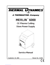
2.1 Mechanical dimensions XT CNC
Cnc dimensions:
Height 17.7 in. (450mm)
Width 15.7 in. (400mm)
Depth 16.9 in. (430mm)
15.35in
(390mm)
0.86in
(22mm)
0.9in
(23mm)
0.83
(21mm)
0.3in
(8mm)
13.6in
(345mm)
0.83
(21mm)
12.6in
(320mm)
23.6in
(600mm)
0.3in
(8mm)
0.3in
(8mm)
0.3in
(8mm)
13.6in
(345mm)
Mounting Plate:
Width 15.35 in. (390mm)
Depth 14.3 in. (363mm)*
Mounting holes 13.7 in. X 12.6 in. x 4xM6 (349mm x 320mm, 4
x M6)
* Max plate thickness 20mm with the provided mounting screws.
* Some users might want to expand the bottom plate from the front side. Usually you would create a space for a keyboard, mouse, or just some
work space for papers etc.

iCNC XT
Manual 0-5299 SPECIFICATIONS 2-3
2.2 Power Requirements
The power connector is located at the backside of the CNC unit. The connector is a standard IEC C14 power connector. Use a IEC C13 plug to
connect the main power to iCNC XT. The power requirement is shown in the product label at the lower left corner in the backside of the CNC.
Use national wiring standards for wire and fuse sizes.
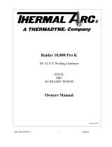
2.3 Mechanical dimensions Yaskawa Motors
SGDV Sigma 5
LL LC
S
See next image
mating dimensions
400W LL = 3.9 in. (98.5mm)
400W LC = 2.36 in. (60mm)
750W LL = 4.5 in. (115mm)
750W LC = 3.15 in. (80mm)
400W S = 0.551 in. (14mm)
750W S = 0.748 in. (19mm)

iCNC XT
2-4 SPECIFICATIONS Manual 0-5299
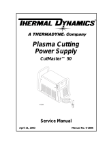
2.4 Mechanical dimensions Neugart Gearboxes
/