Smeg CPF30UGGAN Installation guide

Category
Ovens
Type
Installation guide
Table of Contents
3
EN
1 Installation 8
1.1 Dimension Requirements 8
1.2 Product dimensions 9
1.3 Unpacking, moving and positioning the range 10
1.4 Wall attachment and anti-tip device 11
1.5 Electrical requirements 14
1.6 Gas supply requirements 16
1.7 For the installer 23
WARNING: If the instructions in this manual is not followed exactly, a
fire or explosion may result causing property damage, personal injury
or death.
- Do not store or use gasoline or other flammable vapors or liquids in the
vicinity of this or any other appliance.
- WHAT TO DO IF YOU SMELL GAS
• Do not try to light any appliance.
• Do not touch any electrical switch.
• Do not use any phone in your building.
• Immediately call your gas supplier from a neighbor’s phone. Follow the
gas supplier’s instructions.
• If you cannot reach your gas supplier, call the fire department.
- Installation and service must be performed by a qualified installer, service
agency or gas supplier.
NOTE: This appliance must be installed solely and exclusively by a qualified
technician. Any technical procedures must be carried out by an authorized
technician.
Important Safety Instructions
4
WARNING
TIP OVER HAZARD
• A child or adult can tip the range and be killed.
• Make sure that the anti-tip device has been properly installed
and attached. The wall-mounted brackets should anchor the
sides of the range (primary system) or, in case of floor-
mounted brackets, they should anchor the rear of the range to
the ground.
• Make sure that the anti-tip device is re-attached when the
range is moved. The wall-mounted brackets should anchor the
sides of the range (primary system) or, in case of floor-
mounted brackets, they should anchor the rear of the range to
the ground.
• Do not operate the range without the anti-tip device in place
and attached.
• Failure to do so can result in loss of life or serious burns to
children or adults.
READ AND SAVE THESE INSTRUCTIONS - Your safety and the safety of
others are very important.
We have provided many important safety messages throughout this manual and
on the appliance.
Read all the instructions before using the appliance and always obey all safety
messages.
RECOGNIZE SAFETY INFORMATION
This is a safety alert symbol. This symbol alerts you to potential hazards that can
result in severe personal injury or loss of life.
UNDERSTAND SIGNAL WORDS
A signal word - DANGER, WARNING or CAUTION - is used with the safety alert
symbol. DANGER denotes the most serious hazards. It means you could lose your
life or be seriously injured if you do not immediately follow the instructions.
WARNING means you could lose your life or be seriously injured if the instructions
are not followed. CAUTION indicates a potentially hazardous situation which, if
not avoided, could result in minor to moderate injury.
Important Safety Instructions
5
EN
The safety messages will inform you of potential hazards, on how to avoid the risk of injury
and what can occur if the instructions are not followed.
IMPORTANT: Installation, gas connections and grounding must conform to applicable
codes. Observe all codes and ordinances in force.
Do not store or use gasoline or other flammable vapors, liquids or materials near this or any
other appliance.
WARNING
• This appliance is intended for use in the home only.
• Use this appliance only for its intended purpose. The
manufacturer cannot be held liable for damage caused by
improper use of this range.
• This appliance complies with current safety regulations.
Improper use of this range can result in personal injury and
material damage.
• Read all the instructions before installing or using the range
for the first time.
• Keep these operating instructions in a safe place and pass
them on to any future user.
NOTE: This range is manufactured for use with natural gas. To convert the
appliance to LP/Propane gas, see the instructions in the Gas Conversion Kit
provided in the literature package.
The proper gas supply connection must be available. See “Gas supply
requirements”.
In the State of Massachusetts, the following installation instructions apply:
• Installation and repairs must be performed by a Massachusetts qualified or
licensed contractor, plumber, or gas fitter.
• If using a ball valve, it shall be the T-handle type.
• A flexible gas connector, when used, must not exceed 3 feet.
WARNING: For your safety, the instructions contained in this manual must be
followed to minimize the risk of fire or explosion and to prevent property damage,
personal injury or loss of life.
NOTE: This range is NOT designed for installation in manufactured (mobile)
homes or in recreational vehicles (RVs).
DO NOT install this range outdoors.
Important Safety Instructions
6
• Read all instructions
• Proper installation is your responsibility.
Have a qualified technician install and
ground this appliance in accordance
with these installation instructions.
• It is the responsibility of the installer to
comply with installation information
specified on the model/serial ID plate.
The ID Plates are visibly located on the
back of the appliance and on the oven
door frame. These ID plates must never
be removed.
• ELECTRICAL GROUNDING
REQUIRED: See the “Electrical
Requirements” section. It is the customer’s
responsibility:
• To contact a qualified electrician to
install the appliance
• To ensure that the electrical system is
adequate and conforms with the national
ANSI / NFPA 70 ELECTRICAL CODE –
latest edition – Or the CANADIAN
ELECTRICAL CODE, C22.11 – 1 and
C22.2 No. 01982 – or latest edition –
and all local codes and ordinances.
IMPORTANT: Observe all codes and
ordinances in force.
• Before you plug the electrical cord into
an outlet, make sure that all the
appliance controls are in the OFF
position.
WARNING
To reduce the risk of fire, electrical shock, personal injury, or
damage when using the range, follow basic safety precautions,
including the following:
WARNING
PRIMARY FASTENING SYSTEM:
Visually check that the wall-mounted brackets are inserted into the
appropriate lateral hooks (on both sides).
SECONDARY FASTENING SYSTEM:
Visually check from the inside of the drawer that the floor-mounted
bracket is inserted into the appropriate lateral hooks (left or right).
CAUTION: To eliminate the risk of
burns or fire caused by reaching
over hot surface burners, do not
store items directly above the
rangetop.
Important Safety Instructions
7
EN
• Never modify or alter the construction of
the appliance. For example, do not
remove adjustable legs, panels, wiring
or anti-tip brackets/screws.
• Do not obstruct oven vents or openings
for heat exhaust.
• Test the appliance immediately after
installation, following the instructions in
this booklet. If the appliance does not
work properly, disconnect it from the
electrical power supply and call the
service center. DO NOT attempt to
repair the appliance.
• All adjustments and servicing must be
performed by qualified installers or
service technicians.
• Do not leave the packing material
around the home. Sort the various items
of waste and take them to the nearest
specialized waste collection facility.
How to read the user manual
This user manual uses the following reading
conventions:
1. Use instruction sequence.
• Single use instruction.
SAVE THESE INSTRUCTIONS
CAUTION: This unit is designed as
a cooking appliance. For safety
purposes, never use it for warming
the room or as a space heater.
Installation
Information for the qualified
technician: installation, operation
and inspection.
Safety instructions
Information
Advice
Installation
8
1 Installation
1.1 Dimension Requirements
1. min. clearance from the sides of range to
side wall or other combustible material;
2. min. cabinet opening width;
3. upper cabinet to countertop;
4. min. when bottom of wood or metal
cabinet is protected by not less than ¼”
(0.64 cm) flame retardant millboard
covered with not less than No. 28 MSG
sheet steel, 0.015" (0.4 mm) stainless
steel, 0.024" (0.6 mm) aluminum or
0.020" (0.5 mm) copper. 35" (889 mm)
min. clearance between the top of the
cooking surface and the bottom of an
unprotected wood or metal cabinet.
5. max. upper cabinet depth.
Y - Grounded outlet
Position within 11
7
/
8
" (300 mm) from the
left rear corner of the range.
X - Gas supply line
Position within 11
7
/
8
" (300 mm) from the
right rear corner of the range.
A 766 mm
30
3
/
16
"
B 636 mm 25“
C
1
216 mm
8
1
/
2
"
G
2
766 mm
30
3
/
16
"
I
3
457 mm 18"
L
4
610 mm 24"
M
5
330 mm 13"
N 150 mm
5
15
/
16
"
NOTE: Install with zero
clearance sides and back.
Installation
9
EN
1.2 Product dimensions
Overall dimensions: Location of gas and
electrical connection points.
Check the location where the range is to be
installed. The range should be positioned
for convenient access in the kitchen.
The cabinet opening dimensions that are
shown must be used. The indicated
dimensions are the minimum clearances.
When installing a range under existing
cabinets that do not satisfy the minimum
cabinet clearances, install a rangehood
over the cooking surface to avoid burn
hazards.
An air curtain or other overhead range
hood, which operates by blowing a
downward airflow onto a range, shall not
be used in conjunction with the gas range
unless the hood and range have been
designed, tested in accordance with ANSI
Z21.1 and listed by an independent testing
laboratory for combination use. This type of
ventilation system may cause ignition and
combustion problems with the gas cooking
appliance resulting in personal injury or
unintended operation.
A 53 mm
2
1
/
16
"
B 611 mm
24
1
/
16
"
C 136 mm
5
3
/
8
"
D 23 mm
13
/
16
"
E 762 mm 30"
F 790 mm
31
1
/
8
"
NOTE: Observe all governing
codes and ordinances.
Any openings in the wall or floor
where the range is to be installed
must be sealed.
Some cabinet and building
materials are not designed to
withstand the heat that the oven
produces during baking. Check
with your builder or cabinet
supplier to make sure that the
materials used will not discolor,
delaminate or sustain other
damage.
Installation
10
1.3 Unpacking, moving and
positioning the range
• It is recommended that the grates, the
griddle plate and burner heads, burner
caps, front kick panel and oven racks be
removed to facilitate handling. This will
reduce the weight for moving.
• When positioning the appliance during
installation,
do not use the door handle
to lift up or move this appliance.
• Remove the outer carton and packing
material from the shipping base.
• Remove angle-mounting brackets from
the range.
• Due to the weight, a dolly/fork lift with
soft rubber tread wheels should be used
to move this unit. The weight must be
supported uniformly across the bottom.
• The floor under the legs should be
protected (wood, strips, carpet,
paneling, etc.) before pushing the unit
into position.
The anti-tip device must be installed, and
the gas and electrical connections
should be made before the range is
placed in its final position.
• Ensure that the burner caps are correctly
positioned on the burner bases on the
rangetop.
• Legs should be installed near to where
the appliance will be used as they are
not secure for long transit. Keep the unit
raised so the legs can be screwed into
their couplings, then lower the range
gently to prevent the legs and mounting
hardware from being subject to any
undue strain. Instead of tilting the unit, it is
recommended that a pallet or lift jack be
used.
• For proper performance the range must
be leveled. The range is leveled by
adjusting the four legs to ensure that the
unit is on a perfectly level plane. To
accomplish this, screw or unscrew the
second part of the legs. The adjustment
range of the screw is 1.37 inches (35
mm).
CAUTION: This unit is designed as
a cooking appliance. For safety
purposes, never use it for warming
the room or as a space heater.
NOTE: this appliance must only
use the specific leveling legs
provided by the manufacturer.
Installation
11
EN
1.4 Wall attachment and anti-tip device
Warning
Electrical shock hazard
• Use extreme caution when drilling holes into the wall or floor. There may be concealed
electrical wiring located behind the wall or under the floor.
• Identify the location of the electrical circuits that could be affected by the installation of
the anti-tip device, then turn off power to these circuits.
• Failure to follow these instructions may result in electrical shock or other personal injury.
CAUTION
• Contact a qualified installer or contractor to determine the proper method for
drilling holes through the wall or floor material (such as ceramic tile, hardwood,
etc.)
• Failure to follow these instructions may result in damage to wall or floor
coverings.
WARNING
To reduce the risk of fire, electrical shock, personal injury, or
damage when using the range, follow basic safety precautions,
including the following:
WARNING
PRIMARY FASTENING SYSTEM:
Visually check that the wall-mounted brackets are inserted into the
appropriate lateral hooks (on both sides).
SECONDARY FASTENING SYSTEM:
Visually check from the inside of the drawer that the floor-mounted
bracket is inserted into the appropriate lateral hooks (left or right).
Installation
12
Instructions for wall mounting (primary
system)
1. Assemble the fastening bracket.
2. Align the base of the hook on the
fastening bracket with the base of the
slot on the wall fastening plate.
3. Align the base of the fastening bracket
with the ground and tighten the screws
to fix the measurements.
4. Use 50 mm for the distance from the
side of the appliance to the bracket
holes.
Installation
13
EN
5. Move the bracket onto the wall and
mark the position of the holes to be
drilled in the wall.
6. After drilling the holes in the wall, use
wall plugs and screws to fasten the
bracket to the wall.
7. Push the cooker towards the wall, and
at the same time, insert the bracket in
the plate fastened to the rear of the
appliance.
Instructions for floor mounting
(secondary system)
The secondary anti-tip device is to be
attached to the floor when it is not possible
to install the primary system. After having
positioned and leveled the appliance the
bracket has to be anchored to the floor and
engaged in the slots at the rear of the
appliance.
1. Assemble the fastening bracket as shown
in the figure. Join the two parts without
tightening them too much since there will
be other adjustments to make.
NOTE: According to the type of
floor, the installer should supply the
suitable fastening systems (Type of
screw recommended
3
/
8"
).
Installation
14
2. After having positioned and leveled the
appliance, move the bracket close to the
rear of the appliance and anchor it to the
floor.
3. The bracket attachment should insert into
one of the central slots at the rear.
4. Lower the bracket attachment until
anchoring the appliance slot, tighten the
nuts previously assembled. The anti-tip
device works properly only if the bracket
attachment is securely anchored to the
appliance.
1.5 Electrical requirements
Warning
Electrical shock hazard
• Plug into a grounded 3-prong outlet.
• Do not cut or remove the grounding
prong.
• Do not use an adaptor.
• Do not use an extension cord.
• Check with a qualified electrician if you
are not sure whether the range is
grounded.
FAILURE TO FOLLOW THESE
INSTRUCTIONS COULD
RESULT IN LOSS OF LIFE, FIRE
OR ELECTRICAL SHOCK.
Installation
15
EN
Make sure that the power line rating
matches the specifications indicated on the
ID plate. The ID Plates are visibly located
on the back of the appliance and on the
oven door frame.
These ID plates must never be removed.
Wire size and connections must conform
to the requirements of the National
Electrical Code, ANSI/NFPA 70
ELECTRICAL CODE (*) – last edition or
CSA Standard C22.1-94, Canadian
Electrical code, Part 1 (**) and CSA
C22.2 No. O-91 or latest edition and
all local codes and ordinances for the
kilowatt rating of the range.
IMPORTANT: Observe all governing
codes and ordinances.
• Your local codes and ordinances, of
course, take precedence over these
instructions. Complete electrical
connections according to local codes
and ordinances.
• lf codes permit and a separate
grounding wire is used, it is
recommended that the suitability of the
ground path be checked by a qualified
electrician.
• Check with a qualified electrician if you
are not sure whether the range is
properly grounded. Do not ground to a
gas pipe.
• A 120-volt, 60-Hz, AC-only, 15-
ampere, fused electrical supply is
required. A time-delay fuse or circuit
breaker is recommended. It is
recommended that a separate circuit
serving only this appliance be provided.
Installation
16
Recommended Grounding Method
For your personal safety, this range must be
grounded. This range is equipped with a 3-
prong grounding plug. To minimize possible
shock hazard, the cord must be plugged
into a mating 3-prong grounding
receptacle, grounded in accordance with
the National ANSI/NFPA 70 Electrical
Code (latest edition*) or the Canadian
Electrical Code (CSA)** and local codes
and ordinances. lf a mating receptacle is
not available, it is the personal responsibility
and obligation of the customer to have a
properly polarized and grounded 3-prong
outlet installed by a qualified electrician.
1.6 Gas supply requirements
Copies of the standards listed
above may be obtained from:
* National Fire Protection
Association, 1 Batterymarch Park,
Quincy, Massachusetts 02169-
7471
** CSA International, 8501 East
Pleasant Valley Road, Cleveland
OH 44131-5575
Warning
Explosion hazard
• Use a new AGA or CSA-approved gas
supply line.
• Install a shut-off valve.
• Securely tighten all gas connections.
• lf connected to LP, have a qualified
technician ensure that the gas pressure
does not exceed a 14" W.C.P.
• Examples of qualified technicians
include licensed heating personnel,
authorized gas company personnel,
and authorized service personnel.
• Failure to do so can result in loss of life,
explosion, or fire.
NOTE:
• Observe all codes and
ordinances in force.
The range must be connected to
a standard gas supply.
Installation
17
EN
This installation must conform with all local
codes and ordinances. In the absence of
local codes, installation must conform to
American National Fuel Gas Code, ANSI
Z223.1/NFPA 54 or, in Canada, the
Natural Gas and Propane Installation
Code, CSA B149.1.
If local codes permit, a flexible metal
appliance conductor with the new AGA or
CSA design certified, 4-5 feet (1.2-1.5 m)
long,
1
/
2
" or
3
/
4
" ID NPT, is
recommended for connecting this range to
the gas supply line.
Do not bend or damage the flexible
connector when moving the range. The
pressure regulator has 3/8" female pipe
threads. You will need to determine the
fittings required, depending on the
dimension of your gas supply line, the
flexible metal connector and the shut-off
valve.
The appliance should be installed in rooms
that have a permanent air supply in
accordance with the standards in force. The
room where the appliance is installed must
have enough air flow for the regular
combustion of gas and the necessary air
change in the room itself. The air vents,
protected by grilles, must be the right size to
comply with current regulations and
positioned so that no part of them is
obstructed, not even partially.
The room must be kept adequately
ventilated in order to eliminate the heat and
humidity produced by cooking: in
particular, after prolonged use, you are
recommended to open a window or to
increase the speed of any fans.
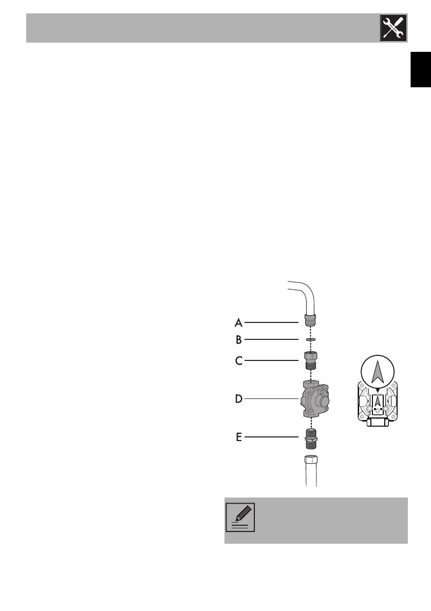
Gas connection
Connect the adapter C (ISO 228/1 -
½ NPT) to the gas inlet of the appliance A
being sure to insert the supplied gasket B.
Apply a suitable sealing substance (such as
Teflon tape) between pressure regulator D
and adapter C.
Connect the pressure regulator D to the
adapter C put on in the previous step (the
arrow on the back of the regulator points
towards the gas inlet of the appliance).
Apply a suitable sealing substance (such as
Teflon tape) between pressure regulator D
and adapter E (½ NPT - ½ NPT) (not
supplied).
Connect the adapter E to the pressure
regulator D.
WARNING: The tightening torque
of adapter (C / E) must not be
greater than 36 ozf - 10 Nm.
Installation
18
Due to problems of overall dimensions at
the back, screw in the pressure regulator so
that it is sloped at 45° vs the wall at the
back of the appliance.
Test the appliance
Follow these instructions to leak test the
appliance:
Use a brush and liquid detergent to test all
gas connections for leaks. Bubbles around
connections indicate a leak. If a leak
appears, shut off the gas valve controls and
adjust the connections. Then check the
connections again. Remove all the
detergent product from the range. Replace
the parts on the burner and turn the knobs
on the gas tap valves.
NEVER TEST FOR GAS LEAKS WITH A
MATCH OR OTHER FLAMES.
Shut-off valve
The supply line must be fitted with an
approved shut-off valve.
This valve should be located in the same
room as the range and should be in a
location where it can be easily opened and
closed.
Do not block access to the shut-off valve.
The valve is necessary for turning the gas to
the appliance on or off.
Installation
19
EN
Incoming line pressure
Incoming line pressure upstream from the
regulator must be 1” (2.5 cm) W.C.P. higher
than the manifold pressure in order to check
the regulator. Incoming line pressure to the
regulator should be as follows for operation
and checking the regulator setting:
Natural Gas: Set pressure to 5” W.C.P.
Incoming line pressure of 6” - 10 1/2”
W.C.P maximum.
LP Gas: Set pressure to 10” W.C.P.
Incoming line pressure 11”- 13” W.C.P.
maximum.
Lubricating the surface burner gas valves
Over time, the surface burner gas valves
may become stiff or jam. Clean them
internally and relubricate. This operation
must be carried out by a qualified
technician.
NOTE: The range must be isolated
from the gas supply piping system
by turning off the respective
manual shut-off valve during any
pressure testing of the gas supply
piping system.
Installation
20
Assembling the backguard
The backguard must always be positioned
and secured correctly on the appliance.
1. Position the backguard above the top,
taking care to align the holes.
2. Secure the backguard to the top by
tightening screws.
3. For the two outermost screws, also
tighten the supplied spacers, as per
figure.
Positioning and levelling
• After making the gas and electrical
connections, screw on the four feet
supplied with the appliance.
The appliance must sit level on the floor to
ensure stability.
• Screw or unscrew the bottom part of the
foot until the appliance is stable and
level on the floor.
The backguard provided is an
integral part of the product; it must
be fastened to the appliance prior
to installation.
Heavy appliance
Risk of damage to the appliance
• Insert the front feet first and then the rear
ones.
Installation
21
EN
Installing the front skirting
The front skirting must always be positioned
and secured correctly on the appliance.
1. Use a screwdriver to remove the front
screws underneath the storage
compartment.
2. Position the front skirting at the bottom of
the appliance and line up the holes of
the front skirting with the holes on the
base of the appliance.
3. Fasten the front skirting to the appliance
using the previously removed screws.
Installation
22
Installing the side skirting
After installing the front skirting, the side
skirting can be fastened correctly to the
appliance.
1. Use a screwdriver to remove the rear
screw underneath the storage
compartment.
2. Position the side skirting on the lower side
section of the appliance below the
storage compartment.
3. Insert the tabs on the side skirting into the
slots on the rear part of the front skirting.
4. Line up the hole on the side skirting with
the rear hole on the base of the
appliance.
5. Fasten the side skirting to the appliance
using the previously removed screw.
6. Repeat the operations described above
for the other side skirting section.
  • Page 1 1
  • Page 2 2
  • Page 3 3
  • Page 4 4
  • Page 5 5
  • Page 6 6
  • Page 7 7
  • Page 8 8
  • Page 9 9
  • Page 10 10
  • Page 11 11
  • Page 12 12
  • Page 13 13
  • Page 14 14
  • Page 15 15
  • Page 16 16
  • Page 17 17
  • Page 18 18
  • Page 19 19
  • Page 20 20
  • Page 21 21
  • Page 22 22

Smeg CPF30UGGAN Installation guide

Category
Ovens
Type
Installation guide

Ask a question and I''ll find the answer in the document

Finding information in a document is now easier with AI