KitchenAid KCGD500GSS Installation guide

Type
Installation guide

This manual is also suitable for

30" (76.2 CM) AND 36" (91.4 CM)
GAS DOWNDRAFT COOKTOP
INSTALLATION INSTRUCTIONS
INSTRUCTIONS D'INSTALLATION DE LA TABLE
DE CUISSON À GAZ À ASPIRATION PAR LE BAS
DE 30" (76,2 CM) ET DE 36" (91,4 CM)
Table of Contents/Table des matières
COOKTOP SAFETY
You can be killed or seriously injured if you don't immediately
You
can be killed or seriously injured if you don't
follow
All safety messages will tell you what the potential hazard is, tell you how to reduce the chance of injury, and tell you what can
happen if the instructions are not followed.
Your safety and the safety of others are very important.
We have provided many important safety messages in this manual and on your appliance. Always read and obey all safety
messages.
This is the safety alert symbol.
This symbol alerts you to potential hazards that can kill or hurt you and others.
All safety messages will follow the safety alert symbol and either the word “DANGER” or “WARNING.”
These words mean:
follow instructions.
instructions.
DANGER
WARNING
W10848427B
IMPORTANT:
Installer: Leave installation instructions with the homeowner.
Homeowner: Keep installation instructions for future reference.
IMPORTANT :
Installateur : Remettre les instructions d’installation au propriétaire.
Propriétaire : Conserver les instructions d’installation pour référence ultérieure.
COOKTOP SAFETY ........................................................................ 1
INSTALLATION REQUIREMENTS .................................................3
Tools and Parts ............................................................................. 3
Location Requirements ................................................................3
Venting Requirements ..................................................................6
Venting Methods ..........................................................................7
Electrical Requirements ...............................................................8
Gas Supply Requirements ...........................................................9
INSTALLATION INSTRUCTIONS .................................................10
Prepare Cooktop ........................................................................10
Install Cooktop ...........................................................................11
Make Gas Connection ...............................................................12
Attach Cooktop to Countertop ..................................................13
Electronic Ignition System .........................................................13
Complete Installation .................................................................14
SÉCURITÉ DE LA TABLE DE CUISSON .....................................15
EXIGENCES D'INSTALLATION ...................................................16
Outillage et pièces ......................................................................16
Exigences d'emplacement .........................................................16
Exigences concernant l'évacuation ...........................................18
Méthodes d'évacuation .............................................................19
Spécifications électriques ..........................................................21
Spécifications de l'alimentation en gaz .....................................21
INSTRUCTIONS D’INSTALLATION .............................................23
Préparation de la table de cuisson ............................................23
Installation de la table de cuisson ..............................................24
Raccordement au gaz ................................................................25
Fixation de la table de cuisson au plan de travail......................26
Système d'allumage électronique..............................................27
Achever l'installation ..................................................................27
2
IMPORTANT: Do not install a ventilation system that blows air downward toward this gas cooking appliance. This type of
ventilation system may cause ignition and combustion problems with this gas cooking appliance resulting in personal injury or
unintended operation.
WARNING: If the information in these instructions is not followed exactly, a fire or
explosion may result causing property damage, personal injury or death.
Do not store or use gasoline or other flammable vapors and liquids in the vicinity of this
or any other appliance.
WHAT TO DO IF YOU SMELL GAS:
Do not try to light any appliance.
Do not touch any electrical switch.
Do not use any phone in your building.
Immediately call your gas supplier from a neighbor's phone. Follow the gas supplier's
instructions.
If you cannot reach your gas supplier, call the fire department.
Installation and service must be performed by a qualified installer, service agency or
the gas supplier.
WARNING: Gas leaks cannot always be detected by smell.
Gas suppliers recommend that you use a gas detector approved by UL or CSA.
For more information, contact your gas supplier.
If a gas leak is detected, follow the “What to do if you smell gas” instructions.
In the State of Massachusetts, the following installation instructions apply:
Installations and repairs must be performed by a qualified or licensed contractor, plumber, or gasfitter qualified or licensed by
the State of Massachusetts.
If using a ball valve, it shall be a T-handle type.
A flexible gas connector, when used, must not exceed 3 feet.
3
INSTALLATION REQUIREMENTS
Tools and Parts
Gather the required tools and parts before starting installation.
Read and follow the instructions provided with any tools
listed here.
Tools needed
Tape measure
Flat-blade screwdriver
Phillips head screwdriver
Drill
Level
6" (15.2 cm) socket
extension
Marker or pencil
Pliers
¼" drill bit
Jigsaw
Ratchet with ³⁄₈" socket
Pipe-joint compound
resistant to LP gas
Noncorrosive leak-
detection solution
1
/
4
" nut driver
Parts supplied
Vent grill
Pre-filter
LP conversion kit
Burner caps
Burner grates
Plenum
Plenum screw pack
Downdraft motor
assembly
Clamping brackets (2)
Bracket attachment
screws (2)
#10-16 x 3.0" clamping
screws
Parts needed
Metal ducting
Vent clamps
Wall cap
6" (15.2 cm) Round Surface Wall Cap Damper Order Part
Number A406
3
1
/
4
" x 10" (8.3 cm x 25.4 cm) Surface Wall Cap Damper
Order Part Number A403
To order, see the “Assistance or Service” section of the Use
and Care Guide.
Check local codes and consult gas supplier. Check existing gas
supply and electrical supply. See the “Electrical Requirements”
and “Gas Supply Requirements” sections.
It is recommended that all electrical connections be made by
a licensed, qualified electrical installer.
Location Requirements
IMPORTANT: Observe all governing codes and ordinances.
When installing cooktop, use minimum dimensions given.
It is the installer’s responsibility to comply with installation
clearances specified on the model/serial/rating plate. The
model/serial/rating plate is located on the bottom of the
cooktop.
The cooktop should be installed in a location away from
strong draft areas, such as windows, doors, and strong
heating vents or fans.
All openings in the wall or floor where cooktop is to be
installed must be sealed.
Cabinet opening dimensions that are shown must be used.
Given dimensions are minimum clearances.
Grounded electrical supply is required. See the “Electrical
Requirements” section. Proper gas supply connection must
be available. See the “Gas Supply Requirements” section.
The cooktop is designed to hang from the countertop by its
side or rear flanges.
The gas and electric supply should be located as shown in
the “Cabinet Dimensions” section so that they are accessible
without requiring removal of the cooktop.
Provide cutout in right rear corner of cabinet enclosure
as shown to provide clearance for gas inlet and power
supply cord.
If cabinet has drawers, drawers will need to be removed
and drawer fronts installed on front of cabinet.
IMPORTANT: An undercounter built-in oven cannot be installed
under this product.
IMPORTANT: To avoid damage to your cabinets, check with
your builder or cabinet supplier to make sure that the materials
used will not discolor, delaminate, or sustain other damage. This
cooktop has been designed in accordance with the requirements
of UL and CSA International and complies with the maximum
allowable wood cabinet temperatures of 194°F (90°C).
Mobile Home - Additional Installation Requirements
The installation of this cooktop must conform to the
Manufactured Home Construction and Safety Standard, Title 24
CFR, Part 3280 (formerly the Federal Standard for Mobile Home
Construction and Safety, Title 24, HUD Part 280). When such
standard is not applicable, use the Standard for Manufactured
Home Installations, ANSI A225.1/NFPA 501A or local codes.
In Canada, the installation of this cooktop must conform with
the current standards CAN/CSA-A240-latest edition, or with
local codes.
4
Product Dimensions
30" (76.2 cm) Cooktop 36" (91.4 cm) Cooktop
A. 21
1
/
2
" (54.6 cm)
B. 19
11
/
16
" (50.0 cm)
C. Model/serial/rating plate location
B
C
A
A. 30" (76.2 cm)
B. 4" (10.2 cm)
C. 6
19
/
32
" (16.8 cm)
D. 18
7
/
16
" (46.8 cm)
E. 1
11
/
16
" (4.3 cm)
recommended
minimum cabinet
to motor clearance
F. 12
1
/
2
" (31.8 cm)
G. 14" (35.6 cm)
H. 28
1
/
4
" (71.4 cm)
GF
D
E
B
H
A
C
B
C
A
A. 21
1
/
2
" (54.6 cm)
B. 19
11
/
16
" (50.0 cm)
C. Model/serial/rating plate location
GF
D
E
B
H
A
C
A. 36" (91.4 cm)
B. 4" (10.2 cm)
C. 6
19
/
32
" (16.8 cm)
D. 18
7
/
16
" (46.8 cm)
E. 10
3
/
8
" (26.4 cm)
recommended
minimum cabinet
to motor clearance
F. 12
1
/
2
" (31.8 cm)
G. 13" (33.0 cm)
H. 34
3
/
8
" (87.3 cm)
5
Cabinet Dimensions
NOTE: After making the countertop cutout, some installations
may require notching down the base cabinet side walls to clear
the cooktop base. To avoid this modification, use a base cabinet
with sidewalls wider than the cutout.
A minimum side clearance of 6" (15.2 cm) is recommended
between side of cooktop and side wall for maximum
ventilation performance.
Cutout Dimensions
B
D
A
E
F
H
I
K
L
K
M
M
C
G
N
J
A. 30" (76.2 cm) on 30" (76.2 cm) models
36" (91.4 cm) on 36" (91.4 cm) models
B. Combustible area above countertop (shown by dashed box above)
C. 30" (76.2 cm) minimum clearance between top of cooktop platform
and bottom of uncovered wood or metal cabinet (24" [61.0 cm]
minimum clearance if bottom of wood or metal cabinet is covered by
not less than
1
/
4
" [0.6 cm] flame-retardant millboard covered with not
less than No. 28 MSG sheet steel, 0.015" [0.04 cm] stainless steel,
0.024" [0.06 cm] aluminum, or 0.020" [0.05 cm] copper)
D. 13" (33.0 cm) recommended upper cabinet depth
E. 2
1
/
8
" (5.4 cm)
F. 19
15
/
16
" (50.6 cm)
G. 18" (45.7 cm) minimum clearance from upper cabinet to countertop
within minimum horizontal clearances to cooktop
H. Junction box or outlet: 12" (30.5 cm) minimum from bottom of
countertop
I. Junction box or outlet: 10" (25.4 cm) from right-hand side of cabinet
J. 28
5
/
8
" (72.7 cm) on 30" (76.2 cm) models
34
3
/
4
" (88.3 cm) on 36" (91.4 cm) models
K. 6" (15.2 cm) minimum distance to nearest left and right side
combustible surface above cooktop
L. 2" (5.1 cm) minimum clearance between back wall and countertop
cutout
M. Gas line opening - Wall: anywhere 6" (15.2 cm) below underside of
countertop. Cabinet floor: anywhere within 6" (15.2 cm) of rear wall
is recommended.
N. 25" (63.5 cm) depth of countertop
A
B
C
D
E
F
G
H
I
J
A. 28
5
/
8
" (72.7 cm) maximum on 30" (76.2 cm) models
34
3
/
4
" (88.3 cm) maximum on 36" (91.4 cm) models
B. 19
15
/
16
" (50.6 cm) maximum on both 30" (76.2 cm) and
36" (91.4 cm) models
C. 8
1
/
2
" (21.6 cm) on 30" (76.2 cm) models
17
1
/
2
" (44.4 cm) on 36" (91.4 cm) models
D. 5
3
/
4
" (14.6 cm) on both 30" (76.2 cm) and 36" (91.4 cm) models
E. 2
1
/
8
" (5.4 cm) minimum space to front edge of cooktop
F. Floor exhaust option
G. 6
1
/
8
" (15.6 cm) for 6" vent system
H. 8
1
/
2
" (21.6 cm) on 30" (76.2 cm) models
17
1
/
2
" (44.4 cm) on 36" (91.4 cm) models
I. 16" (40.6 cm) on both 30" (76.2 cm) and 36" (91.4 cm) models
J. Wall exhaust option
6
Venting Requirements
IMPORTANT: This cooktop must be exhausted outdoors unless
using the Duct-Free Filter Accessory Kit. See the “Venting
Methods” section.
Do not terminate the vent system in an attic or other
enclosed area.
Use a vent cap.
Vent system must terminate to the outside.
Use only a 6" (15.2 cm) round metal vent. Rigid metal vent is
recommended. For best performance, do not use plastic or
metal foil vent.
Before making cutouts, make sure there is proper clearance
within the wall or floor for the exhaust vent.
Do not cut a joist or stud unless absolutely necessary. If a
joist or stud must be cut, then a supporting frame must be
constructed.
The size of the vent should be uniform.
The vent system must have a damper.
Use vent clamps to seal all joints in the vent system.
Use caulking to seal exterior wall or roof opening around
the cap.
Determine which venting method is best for your application.
For Best Performance:
Use 26-gauge minimum galvanized or 25-gauge minimum
aluminum metal vent. Poor quality pipe fittings can reduce
airflow. Flexible metal vent is not recommended.
NOTE: Local codes may require a heavier gauge material.
Metal duct may be reduced to 30-gauge galvanized steel
or 26-gauge aluminized steel if allowed by local codes.
This reduction is based on information in the International
Residential Codes Section M1601.1 (2006 edition).
Do not install 2 elbows together.
Use no more than three 90° elbows.
If an elbow is used, install it as far away as possible from
the vent motor exhaust opening.
Make sure there is a minimum of 18" (45.7 cm) of straight
vent between the elbows if more than 1 elbow is used.
Elbows too close together can cause excess turbulence that
reduces airflow.
Do not use a 5" (12.7 cm) elbow in a 6" (15.2 cm).
Do not reduce to a 5" (12.7 cm) system after using 6" (15.2 cm).
Avoid forming handmade crimps. Handmade crimps may
restrict airflow.
Use a vent cap for proper performance. If an alternate wall
or roof cap is used, be certain the cap size is not reduced
and that it has a backdraft damper.
Use vent clamps to seal all joints in the vent system.
Use caulking to seal exterior wall or roof opening around
the cap.
The length of vent system and number of elbows should be kept
to a minimum to provide efficient performance.
The maximum equivalent length of the vent system is 60 ft
(18.3 m). For altitudes above 4,500 ft (1272 m), reduce
recommended vent run by 20% for best performance.
Cold Weather Installations
An additional backdraft damper should be installed to minimize
backward cold airflow.
Makeup Air
Local building codes may require the use of makeup air systems
when using ventilation systems greater than specified CFM of
air movement. The specified CFM varies from locale to locale.
Consult your HVAC professional for specific requirements in
your area.
7
Venting Methods
Common venting methods are shown for a counter-mounted
downdraft cooktop. The cooktop may be vented through the
wall or floor.
Option 1 - Roof Venting Option 2 - Wall Venting
A
B
A
B
A. 6" (15.2 cm) round roof venting
B. Roof cap
A. 6" (15.2 cm) round wall venting
B. Wall cap
Option 3 - Venting
Between Floor Joist
Option 4 - Venting Behind
Cabinet Kick Plate
A
B
A B
3¼" x 10"
(8.3 cm x 25.4 cm)
A. Wall cap
B. 6" (15.2 cm) round wall venting
A. Wall cap
B. 6" (15.2 cm) round wall venting
Concrete Slab Installations - Exhaust Through Wall
Duct-Free Filter Accessory Kit
The Duct-Free Filter Accessory Kit Part Number JDA7000WX
is now available. Duct-Free Filter Accessory Kit is ideal for both
new construction and kitchen renovation projects because it
provides an easy alternative to the installation of metal ducting
and venting in the downdraft system outside the home. The kit
includes all required hardware, 1 filter, and complete installation
instructions. Replacement Filter Part Number W10177003 is
available.
A
B
C
D
E
F
G
H
I
J
L
M
K
N
A. Wall cap
B. 6" (15.2 cm) round metal vent
C. 16" (40.6 cm) maximum
D. 6" (15.2 cm) round PVC sewer pipe
E. 6" (15.2 cm) round metal duct
F. 6" (15.2 cm) round PVC coupling
G. Concrete slab
H. 6" (15.2 cm) round PVC sewer pipe
I. 6" (15.2 cm) round 90° PVC sewer pipe elbow
J. Tightly pack gravel or sand completely around pipe.
K. 30 ft (9.1 m) max.
L. 6" (15.2 cm) round 90° PVC sewer pipe elbow
M. 6" (15.2 cm) round PVC coupling
N. 12" (30.5 cm) minimum
8
Calculating Vent System Length
To calculate the length of the system you need, add the
equivalent feet (meters) for each vent piece used in the system.
Vent Piece 6" (15.2 cm) Round
45° elbow 2.5 ft
(0.8 m)
90° elbow 5.0 ft
(1.5 m)
6" (15.2 cm) wall cap 0.0 ft
(0.0 m)
3
1
/
4
" x 10" (8.3 cm x 25.4 cm)
to 6" (15.2 cm) transition
4.5 ft
(1.4 m)
6" (15.2 cm) to 3
1
/
4
" x 10"
(8.3 cm x 25.4 cm) transition
1 ft
(0.3 m)
3
1
/
4
" x 10" (8.3 cm x 25.4 cm)
to 6" (15.2 cm) 90° elbow
transition
5.0 ft
(1.5 m)
6" (15.2 cm) to 3
1
/
4
" x 10"
(8.3 cm x 25.4 cm) 90° elbow
transition
5.0 ft
(1.5 m)
3
1
/
4
" x 10" (8.3 cm x 25.4 cm)
90° elbow
5.0 ft
(1.5 m)
3
1
/
4
" x 10" (8.3 cm x 25.4 cm)
flat elbow
12.0 ft
(3.7 m)
3
1
/
4
" x 10" (8.3 cm x 25.4 cm)
wall cap
0.0 ft
(0.0 m)
Example vent system
1- 90° elbow = 5 ft (1.5 m)
8 ft (2.4 m) straight = 8 ft (2.4 m)
1 - wall cap = 0 ft (0 m)
System length = 13 ft (3.9 m)
NOTE: Flexible vent is not recommended. Flexible vent
creates back pressure and air turbulence that greatly reduce
performance.
Electrical Requirements
IMPORTANT: The cooktop must be electrically grounded in
accordance with local codes and ordinances, or in the absence
of local codes, with the National Electrical Code, ANSI/NFPA 70
or Canadian Electrical Code, CSA C22.1.
This cooktop is equipped with an electronic ignition system
that will not operate if plugged into an outlet that is not properly
polarized.
If codes permit and a separate ground wire is used, it is
recommended that a qualified electrical installer determine
that the ground path is adequate.
A copy of the above code standards can be obtained from:
National Fire Protection Association
1 Batterymarch Park
Quincy, MA 02169-7471
CSA International
8501 East Pleasant Valley Road
Cleveland, Ohio 44131-5575
A 120-volt, 60 Hz, AC-only, 15-amp, fused electrical circuit
is required. A time-delay fuse or circuit breaker is also
recommended. It is recommended that a separate circuit
serving only this cooktop be provided.
Electronic ignition systems operate within wide voltage limits,
but proper grounding and polarity are necessary. Check that
the outlet provides 120-volt power and is correctly grounded.
The wiring diagrams are provided with this cooktop. See
“Wiring Diagrams” on a separate sheet. The wiring diagrams
are located on the underside of the cooktop base.
This gas cooktop is not required to be plugged into a GFCI-
(Ground-Fault Circuit Interrupter) outlet or AFCI- (Arc Fault
Circuit Interrupter) type circuit breaker. It is recommended
that you not plug an electric spark ignition gas cooktop or
any other major appliance into a GFCI wall outlet or an AFCI-
type circuit breaker as it may cause these types of circuit
breakers to trip during normal cycling.
Performance of this cooktop will not be affected if operated
on a GFCI/AFCI-protected circuit. However, occasional
nuisance tripping of the GFCI breaker is possible due to the
normal operating nature of electronic gas cooktops.
90˚ elbow
2 ft
(0.6 m)
6 ft (1.8 m)
wall cap
9
Gas Supply Requirements
Observe all governing codes and ordinances.
IMPORTANT: This installation must conform with all local codes
and ordinances. In the absence of local codes, installation must
conform with American National Standard, National Fuel Gas
Code ANSI Z223.1 - latest edition or CAN/CGA B149 - latest
edition.
IMPORTANT: Leak testing of the cooktop must be conducted
according to the manufacturer’s instructions.
Type of Gas
Natural Gas:
This cooktop is factory set for use with Natural gas. If converting
to LP gas, see the “LP Gas Conversion” instructions provided in
the package containing literature. The model/serial/rating plate
located on bottom of the cooktop has information on the types
of gas that can be used. If the types of gas listed do not include
the type of gas available, check with the local gas supplier.
LP Gas Conversion:
Conversion must be done by a qualified service technician.
No attempt shall be made to convert the cooktop from the gas
specified on the model/serial/rating plate for use with a different
gas without consulting the serving gas supplier. See the “Gas
Conversion” instructions provided in the package containing
literature.
Gas Supply Line
Provide a gas supply line of
3
4
" (1.9 cm) rigid pipe to the
cooktop location. A smaller size pipe on longer runs may
result in insufficient gas supply. Pipe-joint compounds
that resist the action of LP gas must be used. Do not use
TEFLON
®†
tape. With LP gas, piping or tubing size should be
1
/
2
" minimum. Usually, LP gas suppliers determine the size
and materials used in the system.
Flexible metal appliance connector:
If local codes permit, use a
1
/
2
" or
3
/
4
" I.D. flexible stainless
steel tubing gas connector, designed by CSA to connect the
cooktop to the rigid gas supply line.
A
1
/
2
" male pipe thread is needed for connection to the
female pipe threads of the inlet to the cooktop pressure
regulator.
Do not kink or damage the flexible metal tubing when
moving the cooktop.
Must include a shut-off valve:
The supply line must be equipped with a manual shut-off
valve. This valve should be located in the same room. It must
be accessible without removing the cooktop, and it should
be in a location that allows ease of opening and closing. Do
not block access to shut-off valve. The valve is for turning on
or shutting off gas to the cooktop.
Gas Pressure Regulator
The gas pressure regulator supplied with this cooktop must be
used. The inlet pressure to the regulator should be as follows
for proper operation:
Natural Gas:
Minimum pressure: 5" (12.7 cm) WCP
Maximum pressure: 7" to 14" (17.8 cm to 35.5 cm) WCP
LP Gas:
Minimum pressure: 10" (25.4 cm) WCP
Maximum pressure: 14" (35.5 cm) WCP
Contact local gas supplier if you are not sure about the inlet
pressure.
Burner Input Requirements
Input ratings shown on the model/serial/rating plate are for
elevations up to 2,000 ft (609.6 m).
For elevations above 2,000 ft (609.6 m), ratings should be
reduced at a rate of 4% for each 1,000 ft (304.8 m) above
sea level (not applicable for Canada).
Gas Supply Pressure Testing
Gas supply pressure for testing regulator must be at least 1"
water column pressure above the manifold pressure shown on
the model/serial/rating plate.
Line pressure testing above ½ psi gauge (14" WCP)
The cooktop and its individual shut-off valve must be
disconnected from the gas supply piping system during any
pressure testing of that system at test pressures in excess
of
1
/
2
psi (3.5 kPa).
Line pressure testing at ½ psi gauge (14" WCP) or lower
The cooktop must be isolated from the gas supply piping
system by closing its individual manual shut-off valve during
any pressure testing of the gas supply piping system at test
pressures equal to or less than
1
/
2
psi (3.5 kPa).
WARNING
Explosion Hazard
Use a new CSA International approved gas supply line.
Install a shut-off valve.
Securely tighten all gas connections.
If connected to LP, have a qualified person make sure
gas pressure does not exceed 14" (36 cm) water
column.
Examples of a qualified person include:
licensed heating personnel,
authorized gas company personnel, and
authorized service personnel.
Failure to do so can result in death, explosion, or fire.
B
A
C
A. Gas supply line
B. Shut-off valve open position
C. To cooktop
®
TEFLON is a registered trademark of Chemours.
10
INSTALLATION INSTRUCTIONS
Prepare Cooktop
Decide on the final location for the cooktop.
IMPORTANT: Do not cut top of product packaging. This may
damage the product.
1. Open product as instructed on product packaging.
2. Remove all items from both sides of the foam and set aside.
Take out packaging foam and set aside to lay cooktop on.
IMPORTANT: Do not place packaging foam on knobs.
3. Using 2 or more people, remove cooktop and place the
cooktop upside down on the packaging foam, making sure
the knobs are not laid on the foam.
4. Remove plenum and plenum screw pack (in the literature
bag).
5. Remove downdraft motor assembly.
6. Place plenum on bottom of cooktop with round opening
to the motor wire harness.
NOTE: All holes are pre-drilled. If all 6 holes do not line up,
reverse plenum.
7. Using a
1
/
4
" nut driver, screw in the 6 screws from the
literature pack to attach plenum.
8. Remove access panel from plenum using a
1
/
4
" nut driver
and set aside.
9. Remove 4 locking nuts and 4 washers from literature bag.
NOTE: Remove the 4 protective caps from the motor
mounting posts.
10. Place blower motor on plenum.
11. Install and finger-tighten the 4 washers and locking nuts that
were removed through the opening of the motor access
panel. Do not over-tighten to allow for motor to rotate.
12. Connect blower electrical connector to cooktop.
WARNING
Excessive Weight Hazard
Use two or more people to move and install cooktop.
Failure to do so can result in back or other injury.
A
B
C
A. Plenum
B. Cooktop
C. Motor wire harness
A
B
A. Access panel
B. 2 screws
A
B
A. Blower motor
B. Plenum
11
13. Using a
1
/
4
" nut driver, screw the electrical junction cover
to the burner box with 2 screws.
14. Remove the 2 screws located in each side of the cooktop
burner box.
Install Cooktop
Install the pressure regulator to cooktop before installing the
cooktop into the cabinet. See the “Make Gas Connection”
section.
1. Install the pressure regulator with the arrow pointing up
toward the bottom of the cooktop base and in a position
where you can reach the regulator access cap.
IMPORTANT: All connections must be wrench-tightened. Do
not make connections to the gas regulator too tight. Making
the connections too tight may crack the regulator and cause
a gas leak. Do not allow the regulator to turn on the pipe
when tightening fittings.
Use only pipe-joint compound made for use with Natural and
LP gas.
Do not use TEFLON
®
tape. You will need to determine the
fittings required depending on your installation.
2. Attach the 2 hold-down brackets to the burner box.
3. Using 2 or more people, lift the cooktop from packaging
foam and install the cooktop into the countertop cutout by
tilting 1 end of the cooktop into the cutout, then lowering the
other end into the cutout.
NOTE: Make sure that the front edge of the cooktop is
parallel to the front edge of the countertop. If repositioning
is needed, lift entire cooktop up from cutout to avoid
scratching the countertop.
4. Rotate motor to align with duct work and attach ducting.
5. Fully tighten motor and, using a
1
/
4
" nut driver, reattach motor
access cover with 2 screws.
IMPORTANT: Verify that the motor access cover is fully
tightened and back on the plenum.
6. Select bracket mounting holes that will allow the bracket to
extend far enough out from the cooktop for the installation of
#10-16 x 3.0" clamping screws.
7. Attach brackets to cooktop base bottom with bracket
attachment screws using the bracket mounting holes
selected in Step 6. Securely tighten screws.
8. Install grease filter.
NOTES:
The filter should always be placed at an angle. As you
face the front of the cooktop, the top of the filter should
rest against the right side of the vent opening.
The bottom of the filter should rest against the left side
of the vent chamber at the bottom.
If the filter is flat against the fan wall, ventilation
effectiveness will be reduced.
9. Install vent grille.
WARNING
Excessive Weight Hazard
Use two or more people to move and install cooktop.
Failure to do so can result in back or other injury.
A
B
C
D
A. Access cap
B. Rear of cooktop
C. Gas pressure regulator
D. Up arrow. Regulator must be installed with
arrow pointing up to cooktop bottom.
A
B
C
D
E
F
G
A. Cooktop
B. Cooktop base
C. Attachment screw
D. Clamping bracket (extends far
enough beyond cooktop base to
allow installation of clamping screws)
E. #10-16 x 3.0" clamping screw (to
be installed in “Attach Cooktop to
Countertop”)
F. Countertop
G. Foam seal
A
B
A. Plenum
B. Grease filter
12
Make Gas Connection
1. Apply pipe-joint compound made for use with Natural and
LP gas to the smaller thread ends of the flexible connector
adapters (see C and G in the following illustration).
2. Attach 1 adapter to the gas pressure regulator and the other
adapter to the gas shut-off valve. Tighten both adapters,
being certain not to move or turn the gas pressure regulator.
3. Use a
15
/
16
" combination wrench and channel lock pliers to
attach the flexible connector to the adapters. Check that
connector is not kinked.
Typical flexible connection
Complete Connection
1. Open the manual shut-off valve in the gas supply line. The
valve is open when the handle is parallel to the gas pipe.
2. Test all connections by brushing on an approved
noncorrosive leak-detection solution. If bubbles appear,
a leak is indicated. Correct any leak found.
3. Remove surface burner caps and grates from packaging.
Place burner caps on burner bases. Burner caps should
be level when properly positioned. If burner caps are not
properly positioned, surface burners will not light. Place
burner grates over burners and caps.
30" (76.2 cm) models
36" (91.4 cm) models
WARNING
Explosion Hazard
Use a new CSA International approved gas supply line.
Install a shut-off valve.
Securely tighten all gas connections.
If connected to LP, have a qualified person make sure
gas pressure does not exceed 14" (36 cm) water
column.
Examples of a qualified person include:
licensed heating personnel,
authorized gas company personnel, and
authorized service personnel.
Failure to do so can result in death, explosion, or fire.
A
B
C
D
E
F
G
H
I
A. Manifold entrance
B. Gas pressure regulator
C. Use pipe-joint compound.
D. Adapter (must have ½" male pipe thread)
E. Flexible connector
F. Adapter
G. Use pipe-joint compound.
H. Manual gas shut-off valve
I.
1
/
2
" or
3
/
4
" gas pipe
B
A
A. Closed valve
B. Open valve
A
C
B
D
A. Small (AUX)
B. Extra large (UR)
C. Extra large (UR)
D. Medium (SR)
A
C
B
E
D
A. Small (AUX)
B. Medium (SR)
C. Large (R)
D. Extra large (UR)
E. Extra large (UR)
13
4. Plug into a grounded 3 prong outlet.
NOTE: If the cooktop does not work after turning on the power,
check that a circuit breaker has not tripped or a household fuse
has not blown. See the “Troubleshooting” section in the Use and
Care Guide for further information.
Attach Cooktop to Countertop
NOTE: This section applies only if you are using clamping
brackets.
1. Place the #10-16 x 3.0" clamping screws into the outermost
hole in the clamping bracket.
2. Check that the cooktop is still level.
3. Use a screwdriver to tighten the screws against the
countertop. Do not overtighten.
Electronic Ignition System
Initial lighting and gas flame adjustments
This cooktop is equipped for electronic auto-reignition by means
of a spark igniter located at the rear of each burner. The burners
are designed to light at any valve rotation that admits sufficient
gas flow to support a flame and to automatically relight following
a loss of flame due to a draft or other adverse condition. This
feature is provided only as a convenience.
Check Operation of Surface Burners
Push in and turn the surface burners control knobs to light.
The surface burner flame should light within 4 seconds. The first
time a surface burner is lit, it may take longer than 4 seconds to
light because of air in the gas line.
Check the flame on High for a blue color. It should be clean and
soft in character. No yellow tip, blowing or lifting of flame should
occur. Occasional orange flashes are normal and reflect different
elements in the air or gas.
After verifying the proper burner operation, turn the control
knobs to OFF.
If burners do not light properly:
Turn surface burner control knob to OFF.
Check that the power supply cord is plugged in and the
circuit breaker has not tripped or the fuse blown.
Check that the gas shut-off valves are set to the open
position.
Check that burner caps are properly positioned on
burner bases.
Recheck operation of surface burners. If a burner does not light
at this point, contact your dealer or authorized service company
for assistance.
Adjust Flame Height
Smart Port Burner System
This cooktop is equipped with a Smart Port Burner System. The
Smart Port Burner System produces a small flame directly under
each grate finger and a larger flame between each grate finger.
The visual difference between the ports will be noticeable when
the burner is used or when adjustments are made to the flame
length.
Adjust the height of top burner flames. The cooktop Low
burner flame should be a steady blue flame approximately
1
/
4
" (0.64 cm) high.
To adjust standard burners:
The flame can be adjusted using the adjustment screw in
the center of the valve stem. The valve stem is located
directly underneath the control knob.
Electrical Shock Hazard
Plug into a grounded 3 prong outlet.
Do not remove ground prong.
Do not use an adapter.
Do not use an extension cord.
Failure to follow these instructions can result in death,
fire, or electrical shock.
WARNING
A
B
C
D
E
F
G
A. Cooktop
B. Cooktop base
C. Attachment screw
D. Clamping bracket (extends far
enough beyond cooktop base to
allow installation of clamping screws)
E. #10-16 x 3.0" clamping screw
F. Countertop
G. Foam seal
A
B
A. Low flame
B. High flame
14
If the low flame needs to be adjusted:
1. Light 1 burner and turn to lowest setting.
2. Remove the control knob.
3. Hold the knob stem in the low position using a pair of pliers.
Use an
1
/
8
" (3.0 mm) flat-blade screwdriver to turn the screw
located in the center of the control knob stem until the flame
is the proper size.
4. Replace the control knob.
5. Test the flame by turning the control from Low to High,
checking the flame at each setting.
6. Repeat above steps for each burner.
Complete Installation
1. Check that all parts are now installed. If there is an extra
part, go back through the steps to see which step was
skipped.
2. Check that you have all your tools.
3. Dispose of/recycle all packaging materials.
4. Use a mild solution of liquid household cleaner and warm
water to clean cooktop before use. Dry thoroughly with a
soft cloth. For more information, see the “Cooktop Care”
section of the Use and Care Guide.
5. Read the “Cooktop Use” section in the cooktop Use and
Care Guide.
6. Reconnect power.
If you need Assistance or Service:
Please reference the “Warranty” section of the Use and Care
Guide.
SÉCURITÉ DE LA TABLE DE CUISSON
Risque possible de décès ou de blessure grave si vous ne
suivez pas immédiatement les instructions.
Risque possible de décès ou de blessure grave si vous
ne suivez pas les instructions.
Tous les messages de sécurité vous diront quel est le danger potentiel et vous disent comment réduire le risque de blessure et
ce qui peut se produire en cas de non-respect des instructions.
Votre sécurité et celle des autres est très importante.
Nous donnons de nombreux messages de sécurité importants dans ce manuel et sur votre appareil ménager. Assurez-vous de
toujours lire tous les messages de sécurité et de vous y conformer.
AVERTISSEMENT
DANGER
Voici le symbole d’alerte de sécurité.
Ce symbole d’alerte de sécurité vous signale les dangers potentiels de décès et de blessures graves à vous
et à d’autres.
Tous les messages de sécurité suivront le symbole d’alerte de sécurité et le mot “DANGER” ou
“AVERTISSEMENT”. Ces mots signifient :
IMPORTANT : Ne pas installer un système de ventilation avec évacuation de l'air vers le bas, qui évacuerait l'air vers cet
appareil de cuisson à gaz. Ce type de système de ventilation peut causer des problèmes d'allumage et de combustion avec cet
appareil de cuisson à gaz et entraîner des blessures corporelles ou le fonctionnement non désiré de cet appareil.
AVERTISSEMENT : Si les renseignements dans ces instructions ne sont pas
exactement observés, un incendie ou une explosion peut survenir, causant des
dommages au produit, des blessures ou un décès.
Ne pas entreposer ni utiliser de l’essence ou d’autres vapeurs ou liquides inflammables
à proximité de cet appareil ou de tout autre appareil électroménager.
QUE FAIRE DANS LE CAS D’UNE ODEUR DE GAZ :
Ne pas tenter d’allumer un appareil.
Ne pas toucher à un commutateur électrique.
Ne pas utiliser le téléphone se trouvant sur les lieux.
Appeler immédiatement le fournisseur de gaz à partir du téléphone d'un voisin. Suivre
ses instructions.
À défaut de joindre votre fournisseur de gaz, appeler les pompiers.
L’installation et l’entretien doivent être effectués par un installateur qualifié, une agence
de service ou le fournisseur de gaz.
AVERTISSEMENT : L’odorat ne permet pas toujours la détection d’une fuite de gaz.
Les distributeurs de gaz recommandent l’emploi d’un détecteur de gaz (homologation UL ou CSA).
Pour d’autre information, contacter le fournisseur de gaz local.
En cas de détection d’une fuite de gaz, exécuter les instructions “Que faire dans le cas d’une odeur de gaz”.
16
Dans l’État du Massachusetts, les instructions d’installation suivantes sont applicables :
Les travaux d’installation et réparation doivent être exécutés par un plombier ou tuyauteur qualifié ou licencié, ou par le
personnel qualifié d’une entreprise licenciée par l’État du Massachusetts.
Si une vanne à boisseau sphérique est utilisée, elle doit comporter une manette “T”.
Si un conduit de raccordement flexible est utilisé, sa longueur ne doit pas dépasser 3 pi.
EXIGENCES D'INSTALLATION
Outillage et pièces
Rassembler les outils et composants nécessaires avant
d'entreprendre l'installation. Lire et observer les instructions
fournies avec chacun des outils de la liste ci-dessous.
Outils nécessaires
Mètre-ruban
Tournevis à lame plate
Tournevis Phillips
Perceuse
Niveau
Rallonge pour clé à douille
de 6" (15,2 cm)
Marqueur ou crayon
Pince
Foret de
1
/
4
"
Scie sauteuse
Clé à cliquet avec douille
de
3
/
8
"
Composé d’étanchéité
des raccords filetés –
résistant au gaz propane
Solution non corrosive de
détection des fuites
Pièces fournies
Grille de ventilation
Pré-filtre
Trousse de conversion
pour l'alimentation au
propane
Chapeaux de brûleur
Grilles de brûleur
Chambre de distribution
Paquet de vis pour
chambre de distribution
Moteur d’aspiration
Brides de fixation (2)
Vis de fixation des
brides (2)
Vis de fixation de
n° 10-16 x 3,0"
Pièces nécessaires
Conduits métalliques
Brides de serrage pour conduit d’évacuation
Bouche de décharge murale
Clapet de bouche de décharge murale à surface arrondie
de 6" (15,2 cm)
Commander la pièce numéro A406
Clapet de bouche de décharge murale à surface de
3¼" x 10" (8,3 x 25,4 cm)
Commander la pièce numéro A403
Pour commander, voir la section “Assistance ou service”
du Guide d’utilisation et d’entretien.
Vérifier les codes locaux et consulter le fournisseur de gaz.
Vérifier l'alimentation en gaz et l'alimentation électrique
existantes. Voir les sections “Spécifications électriques” et
“Spécifications de l'alimentation en gaz”.
Il est recommandé de faire réaliser tous les raccordements
électriques par un électricien qualifié agréé.
Exigences d'emplacement
IMPORTANT : Observer les dispositions de tous les codes
et règlements en vigueur. Lors de l’installation de la table de
cuisson, utiliser les dimensions minimums indiquées.
C'est à l'installateur qu'incombe la responsabilité de
respecter les distances de séparation exigées, spécifiées sur
la plaque signalétique de l'appareil. La plaque signalétique
est située sur le fond de la table de cuisson.
La table de cuisson doit être installée dans un emplacement
à l’écart des zones de forts courants d’air, telles que
fenêtres, portes et évents ou ventilateurs de chauffage.
Toutes les ouvertures dans le mur ou le plancher de
l'emplacement d'installation de la table de cuisson doivent
être scellées.
Respecter les dimensions indiquées pour les ouvertures à
découper dans les placards. Ces dimensions constituent
les valeurs minimales des dégagements de séparation.
Une source d'électricité avec liaison à la terre est nécessaire.
Voir la section “Spécifications électriques”. Une source
de gaz adéquate doit être disponible. Voir la section
“Spécifications de l'alimentation en gaz”.
De par sa conception, la table de cuisson est suspendue sur
le plan de travail, par les rebords des côtés ou de l'arrière.
Veiller à placer les sources de gaz et d'électricité selon les
indications de la section “Dimensions du placard” pour
qu'elles soient accessibles sans avoir à retirer la table de
cuisson.
Prévoir une ouverture dans le panneau arrière du placard à
droite – voir l’illustration – pour le passage de la canalisation
de gaz et du câble d’alimentation électrique.
Si le placard comporte des tiroirs, ces tiroirs doivent être
retirés et l'avant des tiroirs installé sur l'avant du placard.
IMPORTANT : Il n'est pas possible d'installer un four encastré
sous plan de travail sous ce produit.
IMPORTANT : Afin d'éviter d’endommager les placards,
consulter le constructeur de la maison ou le fabricant des
placards pour déterminer si les matériaux utilisés peuvent subir
un changement de couleur, une déstratification ou d'autres
dommages. Cette table de cuisson a été conçue conformément
aux exigences des normes UL et CSA International et respecte
les températures maximales permises de 194°F (90°C) pour les
placards en bois.
17
Résidence mobile – Spécifications additionnelles
à respecter lors de l'installation
L'installation de cette table de cuisson doit être conforme aux
dispositions de la norme Manufactured Home Construction and
Safety Standard, Title 24 CFR, Part 3280 (anciennement Federal
Standard for Mobile Home Construction and Safety, Title 24,
HUD Part 280). Lorsque cette norme n'est pas applicable, utiliser
la norme Standard for Manufactured Home Installations, ANSI
A225.1/NFPA 501A ou respecter les dispositions des codes
locaux.
Au Canada, l'installation de cette table de cuisson doit satisfaire
aux stipulations de la version la plus récente de la norme CAN/
CSA-A240 ou des codes locaux en vigueur.
Dimensions du produit
Table de cuisson de 30" (76,2 cm)
Table de cuisson de 36" (91,4 cm)
A. 21
1
/
2
" (54,6 cm)
B. 19
11
/
16
" (50,0 cm)
C. Emplacement de la plaque signalétique
B
C
A
A. 30" (76,2 cm)
B. 4" (10,2 cm)
C. 6
19
/
32
" (16,8 cm)
D. 18
7
/
16
" (46,8 cm)
E. Dégagement minimal de 1
11
/
16
" (4,3 cm)
recommandé entre la caisse et le moteur
F. 12
1
/
2
" (31,8 cm)
G. 14" (35,6 cm)
H. 28
1
/
4
" (71,4 cm)
GF
D
E
B
H
A
C
B
C
A
A. 21
1
/
2
" (54,6 cm)
B. 19
11
/
16
" (50,0 cm)
C. Emplacement de la plaque signalétique
GF
D
E
B
H
A
C
A. 36" (91,4 cm)
B. 4" (10,2 cm)
C. 6
19
/
32
" (16,8 cm)
D. 18
7
/
16
" (46,8 cm)
E. Dégagement minimal de 10
3
/
8
" (26,4 cm)
recommandé entre la caisse et le moteur
F. 12
1
/
2
" (31,8 cm)
G. 13" (33,0 cm)
H. 34
3
/
8
" (87,3 cm)
18
Dimensions du placard
REMARQUE : Après le découpage de l'ouverture dans le plan
de travail, il est possible que pour certaines configurations
d'installation, il soit nécessaire d'entailler les parois latérales
du placard inférieur pour permettre le passage de la base
de la table de cuisson. Pour éviter cette modification, utiliser
un placard inférieur dont la largeur des parois latérales est
supérieure à celle de l'ouverture découpée.
Un dégagement minimum de 6" (15,2 cm) entre le côté de
la table de cuisson et la paroi latérale est recommandé pour
une performance maximale de ventilation.
Dimensions de l’ouverture à découper
Exigences concernant l'évacuation
IMPORTANT : L'évacuation de cette table de cuisson doit
se faire à l'extérieur à moins d'utiliser la trousse accessoire
de filtration sans conduit de. Voir la section “Méthodes
d'évacuation”.
Ne pas terminer le circuit d'évacuation dans un grenier
ou dans un autre espace fermé.
Utiliser un clapet de conduit.
Le système doit décharger l'air à l'extérieur.
Utiliser uniquement un conduit métallique rond de 6"
(15,2 cm). Un conduit en métal rigide est recommandé. Pour
un rendement optimal, ne pas utiliser de conduit en plastique
ou en aluminium.
Avant d'effectuer des découpes, s'assurer qu'il y a un
dégagement convenable entre le mur ou le plancher pour
le conduit d'évacuation.
On ne doit couper un poteau de colombage ou une solive
que si c’est absolument nécessaire. Dans ce cas, on devra
construire une structure de support appropriée.
La taille du conduit doit être uniforme.
Le circuit d'évacuation doit comporter un clapet.
Au niveau de chaque jointure du circuit d'évacuation,
assurer l'étanchéité avec les brides de serrage.
À l'aide d'un produit de calfeutrage, assurer l'étanchéité
autour de la bouche de décharge à l'extérieur (à travers
le mur ou le toit).
Déterminer quelle méthode d'évacuation est la plus appropriée.
B
D
A
E
F
H
I
K
L
K
M
M
C
G
N
J
A. 30" (76,2 cm) sur les modèles de 30" (76,2 cm)
36" (91,4 cm) sur les modèles de 36" (91,4 cm)
B. Zone de matière combustible au-dessus du plan de travail (espace
délimité par des lignes pointillées ci-dessus)
C. Distance minimale de séparation de 30" (76,2 cm) entre le dessus de
la table de cuisson et le fond d'un placard métallique ou de bois non
couvert (distance de séparation de 24" [61 cm] ou plus si le fond du
placard de métal ou de bois est recouvert d'une plaque d'au moins
1
/
4
" (0,6 cm) de matériau résistant aux flammes, lui-même recouvert
d'une feuille métallique d'une épaisseur correspondant à un calibre
de 28 au moins pour l'acier, 0,015" [0,04 cm] pour l'acier inoxydable,
0,024" [0,06 cm] pour l'aluminium ou 0,020" [0,05 cm] pour le cuivre)
D. Profondeur recommandée pour les placards supérieurs : 13" (33,0 cm)
E. 2
1
/
8
" (5,4 cm)
F. 19
15
/
16
" (50,6 cm)
G. Distance de séparation minimale de 18" (45,7 cm) entre le placard
supérieur et le plan de travail avec distance minimale de séparation
horizontale pour la table de cuisson
H. Boîtier de connexion ou prise électrique; 12" (30,5 cm) ou plus depuis
le bas du plan de travail
I. Boîtier de connexion ou prise électrique; 10" (25,4 cm) depuis le côté
droit du placard
J. 28
5
/
8
" (72,7 cm) sur les modèles de 30" (76,2 cm)
34
3
/
4
" (88,3 cm) sur les modèles de 36" (91,4 cm)
K. Distance de séparation minimale de 6" (15,2 cm) par rapport à la
surface de matériau combustible la plus proche, à gauche ou à droite
au-dessus de la table de cuisson
L. Distance de séparation minimale de 2" (5,1 cm) ou plus entre la paroi
arrière et l'ouverture dans le plan de travail
M. Ouverture pour canalisation de gaz – mur : n'importe où, à 6"
(15,2 cm) au-dessous de la face inférieure du plan de travail. Plancher
du placard : n'importe où, à 6" (15,2 cm) maximum du mur arrière
(recommandation)
N. Profondeur de la table de cuisson 25" (63,5 cm)
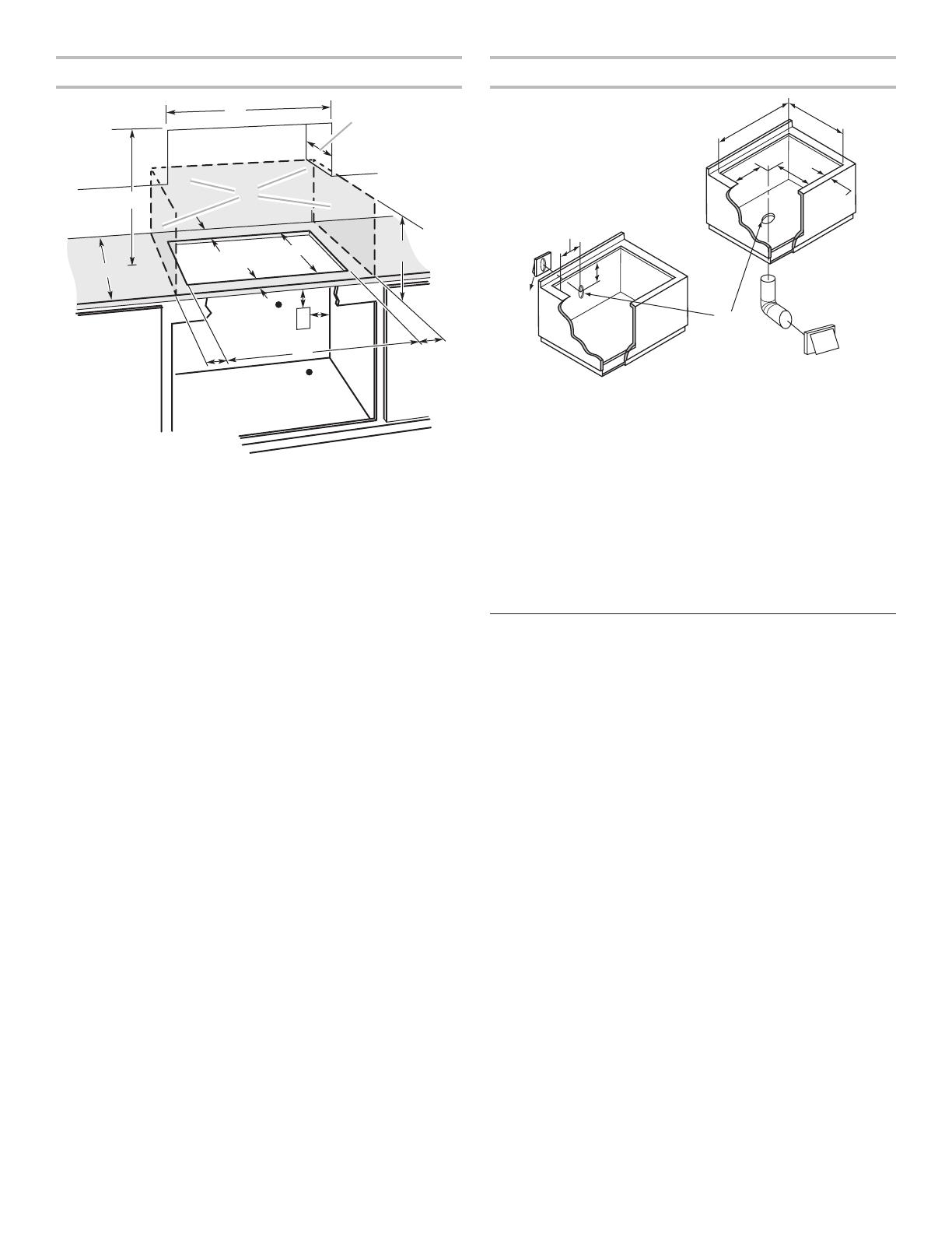
A
B
C
D
E
F
G
H
I
J
A. 28
5
/
8
" (72,7 cm) maximum sur les modèles de 30" (76,2 cm)
34
3
/
4
" (88,3 cm) maximum sur les modèles de 36" (91,4 cm)
B. 19
15
/
16
" (50,6 cm) maximum sur les modèles de 30" (76,2 cm)
et de 36" (91,4 cm)
C. 8
1
/
2
" (21,6 cm) sur les modèles de 30" (76,2 cm)
17
1
/
2
" (44,4 cm) sur les modèles de 36" (91,4 cm)
D. 5
3
/
4
" (14,6 cm) sur les modèles de 30" (76,2 cm) et de 36" (91,4 cm)
E. Dégagement minimal de 2
1
/
8
" (5,4 cm) jusqu'au rebord avant
de la table de cuisson
F. Option d'évacuation par le plancher
G. 6
1
/
8
" (15,6 cm) pour un système d'évacuation de 6"
H. 8
1
/
2
" (21,6 cm) sur les modèles de 30" (76,2 cm)
17
1
/
2
" (44,4 cm) sur les modèles de 36" (91,4 cm)
I. 16" (40,6 cm) sur les modèles de 30" (76,2 cm) et de 36" (91,4 cm)
J. Option d'évacuation par le mur
19
Pour obtenir la meilleure performance :
Utiliser un conduit de ventilation en acier galvanisé
d'épaisseur minimum nº 26 ou en aluminium d'épaisseur
minimum nº 25. Des raccords de mauvaise qualité peuvent
réduire le flux d'air. On déconseille l’emploi d’un conduit en
métal flexible.
REMARQUE : Les codes locaux pourraient exiger un
matériau plus épais.
Le conduit métallique peut être réduit à une épaisseur
nº 30 pour l'acier galvanisé ou nº 26 pour l'acier aluminisé
si c'est permis par les codes locaux. Cette information est
basée sur le contenu de la Section des Codes Résidentiels
Internationaux M1601.1 (édition 2006).
Ne pas installer 2 coudes ensemble.
Ne pas utiliser plus de trois coudes à 90°.
Si l'on utilise un coude, on doit le placer le plus loin possible
de l’ouverture d'évacuation du moteur de ventilation.
Veiller à incorporer une section de conduit rectiligne d'au
moins 18" (45,7 cm) entre deux raccords coudés adjacents.
Des coudes trop rapprochés peuvent occasionner une
turbulence excessive qui réduirait la circulation de l'air.
Ne pas utiliser un coude de 5" (12,7 cm) dans un système
de 6" (15,2 cm).
Ne pas réduire le système à une longueur de 5" (12,7 cm)
après avoir utilisé des raccords de 6" (15,2 cm).
Éviter le sertissage manuel. Cela pourrait restreindre le
flux d'air.
Utiliser un clapet de conduit pour que le rendement soit
correct. Si une bouche de décharge murale ou de toit est
utilisée, s'assurer que la taille de la bouche de décharge
n'est pas réduite et qu'elle comporte un clapet anti-reflux.
Au niveau de chaque jointure du circuit d'évacuation, assurer
l'étanchéité avec les brides de serrage.
À l'aide d'un produit de calfeutrage, assurer l'étanchéité
autour de la bouche de décharge à l'extérieur (à travers le
mur ou le toit).
La longueur du système d'évacuation et le nombre de coudes
doit être réduit au minimum pour une performance efficace.
La longueur maximale équivalente du circuit d'évacuation est
de 60 pi (18,3 m). Pour les altitudes excédant 4 500 pi (1 272 m),
réduire la longueur du système d'évacuation de 20 % pour une
performance optimale.
Installations pour régions à climat froid
On devrait installer un clapet anti-retour additionnel pour
minimiser le reflux d’air froid.
Air d’appoint
Le code du bâtiment local peut exiger l’emploi d’un système
de renouvellement de l’air/introduction d’air d’appoint, lors de
l’utilisation d’un système d’aspiration de débit supérieur à une
valeur (pieds cubes par minute) spécifiée. Le débit spécifié
en pieds cubes par minute varie d’une juridiction à l'autre.
Consulter un professionnel des installations de chauffage/
ventilation/climatisation au sujet des exigences spécifiques
applicables dans la juridiction locale.
Méthodes d'évacuation
Les méthodes d'évacuation standard illustrées correspondent
à une table de cuisson avec aspiration par le bas montée sur
comptoir. L'évacuation de la table de cuisson peut se faire par
le mur ou le plancher.
Option 1 - Décharge
à travers le toit
Option 2 - Décharge
à travers le mur
A
B
A
B
A. Conduit de dia. 6" (15,2 cm)
pour sortie à travers le toit
B. Bouche de décharge sur toit
A. Conduit de dia. 6" (15,2 cm)
pour sortie à travers le mur
B. Bouche de décharge murale
Option 3 - Évacuation
entre les solives au
plancher
Option 4 - Évacuation
derrière le garde-pieds
de la caisse
A
B
A B
3¼" x 10"
(8,3 x 25,4 cm)
A. Bouche de décharge murale
B. Conduit de dia. 6" (15,2 cm)
pour sortie à travers le mur
A. Bouche de décharge murale
B. Conduit de dia. 6" (15,2 cm)
pour sortie à travers le mur
20
Installations dans dalle de béton - Évacuation
à travers le mur
Trousse accessoire de filtration sans conduit
La trousse accessoire de filtration sans conduit, pièce nº
JDA7000WX est désormais disponible. La trousse accessoire
de filtration sans conduit est idéale tant pour les nouvelles
constructions que les projets de rénovation de cuisine parce
qu'elle offre une alternative facile à l'installation de conduits
métalliques et à la décharge de système à aspiration par le bas
vers l'extérieur du domicile. Cet ensemble comprend tout le
matériel nécessaire, un filtre et des instructions d'installation
complètes. Le filtre à charbon de rechange (pièce numéro
W10177003) est disponible.
Calcul de la longueur effective du circuit
d'évacuation
Pour calculer la longueur effective du circuit d’évacuation
nécessaire, additionner les longueurs équivalentes (pieds/
mètres) de tous les composants utilisés dans le système.
Composant Conduit de diamètre
de 6" (15,2 cm)
Coude à 45° 2,5 pi (0,8 m)
Coude à 90° 5 pi (1,5 m)
Bouche de décharge murale
de 6" (15,2 cm)
0 pi (0 m)
Raccord de transition de
3
1
/
4
" x 10" (8,3 cm x 25,4 cm)
sur 6" (15,2 cm)
4,5 pi (1,4 m)
Raccord de transition de 6"
(15,2 cm) à 3
1
/
4
" x 10"
(8,3 cm x 25,4 cm)
1 pi (0,3 m)
Coude de transition à 90° de
3
1
/
4
" x 10" (8,3 cm x 25,4 cm)
à 6" (15,2 cm)
5 pi (1,5 m)
Coude de transition à 90°
de 6" (15,2 cm) à 3
1
/
4
" x 10"
(8,3 cm x 25,4 cm)
5 pi (1,5 m)
Coude à 90° de 3
1
/
4
" x 10"
(8,3 cm x 25,4 cm)
5 pi (1,5 m)
Coude plat de 3
1
/
4
" x 10"
(8,3 cm x 25,4 cm)
12 pi (3,7 m)
Bouche de décharge murale
3
1
/
4
" x 10" (8,3 cm x 25,4 cm)
0 pi (0,0 m)
A
B
C
D
E
F
G
H
I
J
L
M
K
N
A. Bouche de décharge murale
B. Conduit métallique de dia. 6" (15,2 cm)
C. 16" (40,6 cm) maximum
D. Conduit PVC pour égout de dia. 6" (15,2 cm)
E. Conduit métallique de dia. 6" (15,2 cm)
F. Raccord PVC de dia. 6" (15,2 cm)
G. Dalle de béton
H. Conduit PVC pour égout de dia. 6" (15,2 cm)
I. Coude à 90° en PVC pour égout de dia. 6" (15,2 cm)
J. Gravier ou sable compacté tout autour du tuyau.
K. 30 pi (9,1 m) max.
L. Coude à 90° en PVC pour égout de dia. 6" (15,2 cm)
M. Raccord PVC de dia. 6" (15,2 cm)
N. 12" (30,5 cm) minimum
  • Page 1 1
  • Page 2 2
  • Page 3 3
  • Page 4 4
  • Page 5 5
  • Page 6 6
  • Page 7 7
  • Page 8 8
  • Page 9 9
  • Page 10 10
  • Page 11 11
  • Page 12 12
  • Page 13 13
  • Page 14 14
  • Page 15 15
  • Page 16 16
  • Page 17 17
  • Page 18 18
  • Page 19 19
  • Page 20 20
  • Page 21 21
  • Page 22 22
  • Page 23 23
  • Page 24 24
  • Page 25 25
  • Page 26 26
  • Page 27 27
  • Page 28 28

KitchenAid KCGD500GSS Installation guide

Type
Installation guide
This manual is also suitable for

Ask a question and I''ll find the answer in the document

Finding information in a document is now easier with AI

in other languages