
GB
GB
mod. DCM 590 XE
DCM 590 AE
DCM 5100 XE
DCM 5100 AE
INSTRUCTIONS
INSTRUCTIONS
BOOKLET
BOOKLET

Editorial List of contents
Carefully read these instructions before using the appliance and
keep them for future consultation.
Keep potentially hazardous packaging (plastic bags, polystyrene
etc.) out of the reach of children.
Dear Customer,
Thank you for buying a DE DIETRICH appliance.
Our research teams have designed a new generation of kitchen
appliances. As a result of our unique expertise, we have produced
a range of goods whose quality, design and technical advance
are unsurpassed.
You will find that the clean lines and modern look of your
DE DIETRICH appliance blends in perfectly with your kitchen
décor. It is easy to use and performs to a high standard.
DE DIETRICH also makes a range of products that will enhance
your kitchen such as hobs, extractor hoods, built-in dishwashers
and refrigerators. There are models to complement your new DE
DIETRICH hob.
Of course, we make every effort to ensure that our products meet
all your requirements, and our Customer Relations department is
at your disposal, to answer all your questions and to listen to all
your suggestions (see back cover of manual).
DE DIETRICH is certain that by setting new standards of
excellence by which comparisons can be made, customers will
find that DE DIETRICH appliances offer a better and more
exciting way of living.
DE DIETRICH.
Using your appliance in complete safety 3
Installing your appliance in all simplicity 4
Overall dimensions 4
Gas connecting 5
Gas adyustment 6
Electrical connection 6
Using your appliance in all simplicity 7
Using gas burner 7
Use of the electric oven 7
Use of the grill 8
Care and maintenance 10
2

Using your appliance in complete safety
ENVIRONMENT PROTECTION
Packing disposal
Sort packing into different materials (cardboard, polystyrene
etc.) and dispose of them in accordance with local waste
disposal laws.
This appliance complies with the following European Directives:
- 73/23/EEC regarding "Low Voltage".
- 89/336/EEC regarding "Electromagnetic Disturbances".
- 90/396/EEC regarding Gas appliances
- 89/109/EEC regarding "Materials in contact with food"
- Moreover the above mentioned Directives comply with Directive
93/68/EEC.
- This household appliance has been designed for cooking and
it must therefore be used for this purpose only.
IN CASE OF FIRE:
In case of fire, close
immediately the main valve of the gas
pipe line, disconnect current and never pour water on firing
oil in any case.
Do not store flammable products or aerosol containers near the
burners, and do not vaporize them near lighted burners.
FOR YOUR SAFETY AND THE ONE OF YOUR CHILDREN.
Do not store items that are attractive to children above or near
the appliance.
Keep children well away from the appliance: do not forget that
some parts of the appliance or of the pans become very hot and
dangerous during use, and also for all the time necessary to cool
down.
In order to avoid any unintentional fall down, pan handles should
be turned to the back of the cooker, not out to the room or over
adjacent burners.
When cooking, do not use clothes with large flaving and
flammable sleeves; in case of firing you can suffer very serious
harms.
WARNING - OVEN:
When the oven or the grill are in use, accessible parts can
become very hot; it is necessary to keep children well away
from the appliance.
- Never cook food on the lower wall of the oven.
- In case of careless use, in proximity of the oven door hinges,
there is hurt danger.
- Do not let children sit down or play with the oven door. Do not
use the drop down door as a stool to reach above cabinets.
WARMING CABINET
You must not place inflammable materials or plastic utensils in the
warming cabinet (placed below the oven).
ATTENTION:
- Before using the appliance, do not forget to remove the plastic
films protecting some parts of the appliance (facia-panel, parts
in stainless steel, etc.)
- Do not use the appliance as a space heater.
- When the appliance is not in use, we recommend
to disconnect
the current and to close the gas general tap.
3
This appliance is marked according to the European directive
2002/96/EC on Waste Electrical and Electronic Equipment
(WEEE).By ensuring this product is disposed of correctly, you will
help prevent potential negative consequences for the environment
and human health, which could otherwise be caused by inappropriate
waste handling of this product.
The symbol on the product, or on the documents accompanying
the product, indicates that this appliance may not be treated as
household waste. Instead it shall be handed over to the applicable
collection point for the recycling of electrical and electronic
equipment. Disposal must be carried out in accordance with local
environmental regulations for waste disposal.For more detailed
information about treatment, recovery and recycling of this product,
please contact your local city office, your household waste disposal
service or the shop where you purchased the product.

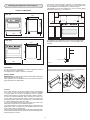
Installing your appliance in all simplicity
ADJ. MAX 15mm
ADJ. MAX 50mm
min. 20mm
min.100 mm
min. 50 mm min. 50 mm
min. 650 mm
min. 400 mm
min. 20mm
OK NO
WARNINGS
Do not use the oven door handle to move the appliance, such as
to remove it from the packaging.
The appliance is in class 1 or class 2 subclass 1.
INSTALLATION
IMPORTANT: The coating of the furniture must be able to withstand
high temperatures (min. 90°C).
If the appliance is to be installed near units, leave the minimum
gaps specified in the table below.
The cooker may be located in a kitchen, or a bed-sitting room,
but not in a room containing a bath or shower. The cooker must
not be installed in a bed-sitting room of less than 20m
3
.
LPG Models must not be installed in a room or internal space
below ground level, e.g. in a basement.
OVERALL DIMENSIONS
4
The appliance is provided with 4 feet used for possible height
alignment with the cabinets. (see fig. 1 or 2 according to the
models).
895
Mod. 590
Mod. 5100
1000
600
900
960
Fig. 1
Location
Your cooker is heavy, so be careful when moving or positioning
it. Do not try to move the cooker by pulling on the doors, handles
or control panel. The cooker is designed to slot in between
600mm deep cabinets, spaced approximately 1000mm apart. It
can also be used free-standing, with a cabinet to one side, in a
corner setting or with its back to a wall. However, it must not be
situated with either side closer than 20mm to a combustible wall
or cupboard that is higher than the cooker.
In case of installation between kitchen units, their sides must
withstand a temperature of at least 90 degrees C.
The wall behind the cooker and 450mm above and across the
width of the cooker, should be an incombustible material or easy
clean surface such as ceramic tiles.
We do not recommend positioning the cooker below wall cupboards,
as the heat and steam from the cooker may cause damage to the
cupboard and its contents.
Lift the cooker and screw the four feet in the special threads
located in the corners under the appliance.
Fig. 2
Mod. 590
Mod. 5100
600
100
850/900
910/960

GAS CONNECTING
Gas Connection
Prior to installation, ensure that the local distribution conditions
(nature of the gas and gas pressure) and the adjustment conditions
are compatible. The adjustment conditions for this appliance are
stated on the rating plate placed on the inside of the front appliance
drawer.
This appliance is not designed to be connected to a combustion
products evacuation device. Particular attention should be given
to the relevant requirements regarding ventilation.
Connection to the cooker should be made with an approved
appliance flexible connection to BS 669. Models for use with LPG
should be fitted with a hose suitable for LPG and capable of
withstanding 50mbar pressure. A length of 0.9 to 1.25m is
recommended. The length of hose chosen should be such that
when the cooker is in situ, the hose does not touch the floor.
The temperature rise of areas at the rear of the cooker that are
likely to come in contact with the flexible hose do not exceed 70
0
C.
Gas pressure may be checked on a semi-rapid hob burner. Remove
the appropriate injector and attach a test nipple. Light the other
burners and observe that the gas pressure complies with the gas
standards in force.
This appliance shall be installed in accordance whit the regulations
in force and only in a well-ventilated space. Read the instructions
before installing or using this appliance.
IMPORTANT
This cooker is supplied for use on Natural Gas Only and cannot
be used for any other gas without modification.
Conversion for use on LPG and other gases must only be
undertaken by a qualified person. For information for use on other
gases contact your local Service Centre.
The cooker must be installed by a qualified person in accordance
with the Gas Safety (Installation and Use) (Amendment) Regulations
1990 and the relevant building/I.E.E. Regulations.
Failure to install the appliance correctly could invalidate any
manufacturers warranty and lead to prosecution under the above
quoted regulations.
In the UK, CORGI registered installers are authorised to undertake
the installation and service work in compliance with the above
regulations. All Comet authorised installers are CORGI registered.
Provision for Ventilation
The room containing the cooker should have an air supply in
accordance with BS 5440: Part 2: 1989. The room must have an
opening windows or equivalent; some rooms may also require a
permanent vent. If the room has a volume between 5 and 10m
3
,
it will require an air vent of 50cm
2
effective area unless it has a
door which opens directly to the outside. If the room has a volume
of less than 5m
3
, it will require an air vent of 100cm
2
effective
area. If there are other fuel burning appliances in the same room,
BS 5440: Part 2: 1989 should be consulted to determine air vent
requirements. Ensure that the room containing the cooker is well
ventilated, keep natural ventilation holes or install a mechanical
ventilation device (mechanical cooker hood). Prolonged intensive
use of the appliance may call for additional ventilation, for example
opening of a window, or more effective ventilation, for example
increasing the level of mechanical ventilation where present. This
cooker is not fitted with a device for discharging the products of
combustion. Ensure that the ventilation rules and regulations are
followed. Excess steam from the oven, vents out at the top back
edge of the cooker, so make sure that the walls behind and near
the cooker are resistant to heat, steam and condensation. Your
cooker must stand on a flat surface so that when it is in position
the hob is level. When in position check that the cooker is level
by using a spirit level and adjust the 2 feet at the rear and the 2
feet at the front if necessary. It is important that the cooker is stable
and level for the overall cooking performance.
Remember that the quantity of air necessary for combustion must
never be less than 2m
3
/h for each kW of power (see total power
in kW on the appliance data plate placed on the inside of the front
appliance drawer).
Gas Safety (Installation & Use) Regulations
It is the law that all gas appliances are installed by competent
persons in accordance with the current edition of the Installation
& Use Regulations. It is in your interest and that of safety to
ensure compliance with the law.
In the UK, CORGI registered installers work to safe standards of
practice. The cooker must also be installed in accordance with BS
6172/1990. Failure to install the cooker correctly could invalidate
the warranty liability claims and could lead to prosecution.
5
(G 1/2) - ISO 7-1
The cookers can be set for sypply both on the right or lefthand
side. In this case it is sufficient to reverse the position of the cad
nipple reducer. At the end make sure than there is no leakage of
gas.
STOP
INLET

GAS ADJUSTMENT
Z
2
1
3
4
5
L
N
A
Conversion to LPG
Always isolate the cooker from the electricity supply, turn off the
gas supply temporarily and proceed as follows.
- change the injectors,
- adjust the minimum flow of the burners.
REPLACEMENT OF WORK-TOP INJECTORS
In order to change the work-top injectors, it is necessary to act as
follows: remove the grids, remove burners and flame-spreaders
(see fig.A), change the injector (see fig.B) and replace it with
another one suitable for the new type of gas (see table D). Re-
assemble everything in the opposite direction, paying attention to
place the flame-spreader in the right way on the burner.
AB
Fig. 4 Fig. 5
MINIMUM FLOW ADJUSTMENT FOR WORK-TOP TAPS
In order to adjust the minimum, act as follows: switch the burner
on, and turn the knob towards the minimum flow position .
Remove the knob from the tap, introduce a little screwdriver in
the tap rod (fig. 4).
Attention: in taps with security valve, the minimum adjusting screw
Z is placed outside the rod tap (fig. 5).
Unscrew the adjusting screw in order to increase the flow or screw
it to decrease the flow.
The right adjustment is obtained when the flame has a length of
about 3 or 4 mm.
For butane/propane gas, the adjusting screw must be tight screwed.
Make sure that the flame does not go out passing quickly from
the max. flow to the minimum flow .
Assemble the knob again.
IMPORTANT
The wires in the mains lead are coloured in accordance with the
following code:
GREEN AND YELLOW .....EARTH
BLUE .................................NEUTRAL
BROWN.............................LIVE
REPLACEMENT OF THE CABLE
In case the cable is damaged, replace it in accordance with the
following instructions:
- open the box of the supply board as described on the picture
below;
- unscrew screw A fixing the cable;
- replace the cable with one of the same lenght and in accordance
with the features described on the table; switch the appliance
off, and close the gas tap
- the green-yellow earth wire must be connected to the terminal
and it must be about 10 mm longer thean the live wires;
- the blue neutral wire must be connected to the terminal marked
with letter N;
- the live wire must be connected to the terminal marked with letter
L.
ELECTRICAL CONNECTION
This appliance must be installed by a qualified person in
accordance with the latest edition of the IEE Regulations and
in compliance with the manufacturer instructions.
Ensure that the voltage is the same as that stated on the rating
plate. The rating plate which can be found on the inside of the
front appliance drawer.
WARNING! THIS APPLIANCE MUST BE EARTHED
If an fixed appliance is not equipped with supply cable and plug,
the power supply must be fitted with a disconnect switch in which
the distance between contacts permits total disconnection in
accordance with overvoltage category III, as required by installation
regulations.
Be sure that the earth wire green/yellow is not interrupted
by the switch
We recommend that the cooker circuit is rated to 20 amps.
Cable type HO5 RRF 3 X 1.5 mm
2
Connecting the mains cable
Open the mains terminal block cover as shown, unscrew screw
A the cable clamp and unscrew (not fully) the screws in the
mains terminal block L N E which secure the three wires of the
mains cable. Fit the cable and refit screw A the cable clamp.
Allow sufficient cable length for the cooker to be pulled out for
cleaning, but do not let it hang closer than 50mm (2) to the floor.
The cable can be looped if necessary, but make sure that it is not
kinked or trapped when the cooker is in position.
6
Values referred to Hs - 15°C - 1013,25mbar
TAB. D
Cat. II 2H3+
GENERAL INJECTORS TABLE
Kind of gas
mbar
Nozzle
Burners
Power
KW Consum
N° max. min. max. min.
115
Rapide
3,00 0,75 286 l/h 72 l/h reg.
NATURAL 20 97
Semi rapide
1,75 0,48 167 l/h 46 l/h reg.
G 20 72
Auxiliary
1,00 0,33 95 l/h 31 l/h reg.
128
Triple crown
3,30 1,30 315 l/h 124 l/h reg.
BUTANE 28-30 85
Rapide
3,00 0,75 219 g/h 55 g/h 42
G 30 65
Semi rapide
1,75 0,48 128 g/h 35 g/h 31
50
Auxiliary
1,00 0,33 73 g/h 24 g/h 27
PROPANE 37 93
Triple crown
3,30 1,30 241 g/h 95 g/h 60
G 31
N°
By pass

Using your appliance in all simplicity
USING GAS BURNERS
The following symbols are on the control panel next to each knob:
- Black circle gas off
- Large flame maximum setting
- Small flame minimum setting
The minimum position is at the end of the anti-clockwise rotation
of the knob. All operation positions must be chosen between the
positions of max. and min., never choose them between max. and
off.
The gas burners are equipped with a thermocouple safety device
to prevent gas from leaking out. This device ensures that the gas
supply is shut off if the flame on the gas burner is extinguished
while the burner is in use.
AUTOMATIC ELECTRIC IGNITION
To turn on a burner, press the knob corresponding to the selected
burner and turn it anticlockwise to the max. position. Keeping
the knob pressed, the electric automatic ignition of the burner will
be started up.
Hold the knob in for around 10 seconds once the flame has
ignited to allow the thermocouple to heat up.
In case there is no electric current, the burner can also be lighted
using a match.
ENERGY SAVING TIPS
The diameter of the pan bottom should be the same as that of
the burner. The burner flame must never come out from the
pans diameter.
Use flat-bottomed pans only.
Whenever possible, keep a lid on the pan while cooking.
You will not need as much heat.
Cook vegetables, potatoes, etc. with as little water as possible
to reduce cooking times.
USE OF THE ELECTRIC OVEN
The first time the oven is used, it may give off acrid smells, caused
by the first heating of isolating panels glue surrounding the oven
(it is necessary to heat up the oven at the maximum
temperature for about 30-40 minutes with closed door).
It is something normal, and in case it will occur, wait for the smoke
to stop before introducing the food into the oven.
The oven is fitted with: a rod shelf for cooking food contained in
oven dishes or placed directly on the rod shelf itself, a drip-tray
for cooking sweets, biscuits, pizzas, etc., or for collecting juices
and fats from food cooked directly on the rod shelf.
Note: The following tables give the main points for cooking some
of the most important dishes. The cooking times recommended
in these tables are approximate. After a few tries, we are sure that
you will be able to adjust the times to get the results you want.
Conventional cooking table
Fan oven cooking table
Dish Temp. °C. Minutes Weight kg.
Firs courses
Lasagne 200-220 20-25 0,5
Oven pasta 200-220 25-30 0,5
Creole rice 200-230 20-25 0,5
Pizza 210-230 30-45 0,5
Meat
Roast veal 160-180 65-90 1-1,2
Roast pork 160-170 70-100 1-1,2
Roast ox 170-190 40-60 1-1,2
Roast beef joint 170-180 65-90 1-1,2
Roast fillet beef (rare) 180-190 40-45 1-1,5
Roast lamb 140-160 100-130 1,5
Roast chicken 180 70-90 1-1,2
Roast duck 170-180 100-160 1,5-2
Roast goose 160-180 120-160 3-3,5
Roast turkey 160-170 160-240 5 approx.
Roast rabbit 160-170 80-100 2 approx.
Roast hare 170-180 30-50 2 approx.
Fish 160-180 acc. to weight
Sweets (pastries)
Fruit flan 180-200 40-50
Plain sandwich cake 160-180 35-45
Sponge sandwich cake 200-220 40-45
Sponge cake 200-230 25-35
Currant cake 230-250 30-40
Buns 170-180 40-60
Strûdel 160 25-35
Cream slices 180-200 20-30
Apple fritters 180-200 18-25
Sponge finger pudding 170-180 30-40
Sponge finder biscuits 150-180 50-60
Toasted sandwiches 230-250 7
Bread 200-220 40
Dish Temp. °C. Minutes
Fish 180-240 acc. to size
Meat
Roast ox 250 30 per kg.
Roast veal 200-220 30 per kg.
Chicken 200-240 50 about
Duck and goose 220 acc. to weight
Leg of mutton 250 30 per kg.
Roast pork 250 60 per kg.
Soufflets 200 60 per kg.
Sweets (pastries)
Tea-cake 160 50-60
Sponge finger 160 30-50
Shortcrust pastry 200 15
Puff pastry 250 15
Fruit flan 200-220 30
Meringues 100 60
Quiches, etc. 220 30
4 quarters 120-140 60
Buns 160-180 45
BURNERS PANS
Ø min. Ø max
RAPIDE 180 mm 220 mm
SEMIRAPIDE 120 mm 200 mm
AUXILIARY 80 mm 160 mm
TRIPLE CROWN 220 mm 260 mm
7

- MULTIFUNCTIONAL OVEN
The oven is fitted with:
a lower heating element;
an upper heating element;
a circular heating element surrounding the fan.
N.B.: Always set the temperature on the thermostat knob before
selecting any of the functions.
Oven thermostat knob
To obtain an oven temperature between 60°C and MAX°C, turn the
knob clockwise.
Oven commutator knob
Depending on the type of oven, it is possible to select one of the
following functions turning the commutator knob clockwise.
Note:
All the functions mentioned above switch the oven internal light on. A
warning light on the control panel will stay lit until the temperature is
reached; after it will light up intermittently.
USE OF THE GRILL
8
When you turn the control knob to this position, the light will be
on for all the following operations.
Defrosting with fan
The air at ambient temperature is distributed inside the oven for
defrosting food very quickly and without proteins adulterations.
Natural convection
Both the lower and upper heating elements operate together.
This is the traditional cooking, very good for roasting joints, ideal
for biscuits, baked apples and crisping food.
You obtain very good results when cooking on a shelf adjusting
the temperature between 60 and MAX°C.
Fan oven
Both the fan and the circular heating element operate together.
The hot air adjustable between 60 and MAX°C is evenly distributed
inside the oven. This is ideal for cooking several types of food
(meat, fish) at the same time without affecting taste and smell.
It is indicated for delicate pastries.
Medium grill
It is indicated for grilling and gratinating small quantities of traditional
food.
The thermostat knob must be placed on the maximum position.
Total grill
It is indicated for grilling and gratinating traditional food.
Turn the thermostat control knob to the 200°C position
as maximum temperature.
Fan assisted total grill
The air which is heated by the grill heating element is circulated
by the fan which distributes the heat on the food.
The fan assisted grill replaces perfectly the turnspit. You can obtain
very good results also with large quantities of poultry, sausage,
red meat. Turn the thermostat control knob to the 200°C position
as maximum temperature.
Air forced lower heating element
The air which is heated by the lower heating element is circulated
by the fan which distributes the heat on the food.
This function can be used to sterilize food. This function can be
used between 60 and MAX°C
Use of the oven
Always use the oven with the oven door closed.
When the functions are used, place the thermostat knob
between 180 ÷ 200°C as maximum temperature.
ATTENTION:
The temperature shown on the control panel corresponds to the
temperature in the oven centre only when the functions selected
are or .
60
125
150
100
80
175
200
225
max
Install the grid on the third shelf from the oven bottom, at about
12 cm from the surface.
The user can change the shelves, depending on his personal
whishes and on the different food.
Geat the oven 5 minutes before introducing the food.

Setting
To set, press and release the desired function, and within 5 seconds
set the time with + and - buttons.
+ and - buttons.
The + and - buttons increase or decrease the time at a speed
depending on how long the button is pressed.
Setting the time
Press any two buttons manual at the same time, and + or - button
to set the desired time. This deletes any previously set programme.
The contacts are switched off .
Manual use
By pressing the manual button the relay contacts switch on, the
AUTO symbol switches off and the saucepan symbol lights up.
Manual operation can only be enabled after the automatic
programme is over or it has been cancelled.
Automatic use
Press the cooking time or end time button to switch automatically
from the manual to the automatic function.
Semi-automatic use with cooking time setting
Press the cooking time button and set the desired time with + or
-. The AUTO and cooking time symbols light up continuously. The
relay switches on immediately. When the cooking end time
corresponds to the time of day, the relay and cooking time symbol
switch off, the sound signal rings and the AUTO symbol flashes.
Semi-automatic use with end time setting
Press the end time button. The time of day appears on the display.
Set the cooking end time with + button. The AUTO and cooking
time symbols light up continuously. The relay contacts switch on.
When the cooking end time corresponds to the time of day, the
relay and the cooking time symbol switch off. When the cooking
time is up, the AUTO symbol flashes, the sound signal rings and
both the relay and the cooking time button switch off.
Automatic use with cooking time and end time setting
Press the cooking time button and select the length of the cooking
time with + or - button. The AUTO and cooking time symbols light
up continuously. The relay switches on. By pressing the cooking
end time button the next cooking end time appears on the display.
Set the cooking end time with + button. The relay and the cooking
time symbol switch off.
The symbol lights up again when the time of day corresponds to
the cooking start time. When the cooking time is up, the AUTO
symbol flashes, the sound signal rings, the cooking time symbol
and the relay switch off.
Minutes counter
Press the minutes counter button and set the cooking time with
+ or - button.
The bell symbol lights up when the minutes counter is operating.
When the set time is up, the sound signal rings and the bell symbol
switches off.
Sound signal
The sound signal starts at the end of a programme or of the minutes
counter function and it lasts for 15 minutes.
To stop it, push any one of the functions buttons.
Start programme and check
The programme starts 4 seconds after it has been set.
The programme can be checked at any time by pressing the
corresponding button.
Setting error
A setting error is made if the time of day on the clock falls within
the cooking start and end times.
To correct the setting error, change the cooking time or cooking
end time.
The relays switch off when a setting error is made.
Cancelling a setting
To cancel a setting, press the cooking time button a nd then press
the - button until 00 00 appears on the display.
A set programme will automatically cancel on completion.
INSTRUCTIONS FOR USE OF CONTROL DEVICES
Features
24 hours clock with automatic programme and minutes counter.
Functions
Cooking time, cooking end time, manual position, clock,
minutes counter, times to be set up to 23 hours 59 minutes.
Display
4-figures, 7-segments diplay for cooking times and time of day.
Cooking time and manual function = saucepan symbol
Automatic function = AUTO
Minutes counter = bell symbol
The symbols light up when the corresponding functions are
selected.
9
Minute timer
Cooking time
Cooking end
Manual
Subtract time
Add time
A
U
T
O

CARE AND MAINTENANCE
Before cleaning the appliance, disconnect the gas general
tap and unplug the appliance or disconnect power at the
main circuit breaker of the electrical system.
Do not clean the appliance surfaces when still hot.
IMPORTANT
Periodically check the external gas connection hole and
replace it when it shows any sign of deterioration. Do not
attempt to repair the gas hose under any cincumstances.
ENAMELLED SURFACES
Clean with a damp sponge using soap and water.
Grease can be easily removed using hot water or a specific
cleansing agent for enamelled surfaces. Do not use abrasive
cleansers.
Do not leave any acid or alkaline substances (lemon juice, vinegar,
salt, etc.) on the enamel.
Clean the parts in stainless steel with specific cleansers for
stainless steel surfaces.
These detergents must be applied using a soft cloth.
GRIDS AND BURNERS
To clean the work-top burners, remove them by pulling upwards
and soak them for about 10 minutes in hot water with a little
detergent. After having cleaned and washed them, wipe them
carefully.
Make sure that no burner hole is clogged.
Clean the burners once a week or more frequently if necessary.
MAKE SURE YOU HAVE ASSEMBLED THE BURNERS IN A
RIGHT WAY.
Do not use steam cleaners to clean the oven.
OVEN
Clean the enamelled parts with a damp sponge using soap and
water. Grease can be easily removed using hot water or a specific
cleansing agent for enamelled surfaces.
Do not use abrasive cleansers.
10


Any work on your appliance must be carried out by a qualified professional brand dealer.
When you call, give the full details of your appliance (model, type, serial number).
This information is shown on the rating plate.
ORIGINAL PARTS: in the case of maintenance work, request exclusive use of
CERTIFIED ORIGINAL SPARE PARTS.
After-sales Service
De Dietrich - 7, rue Henri Becquerel - 92854 RUEIL MALMAISON CEDEX
Tél. : 33 (0) 1 47 16 65 65
S.A.S. au capital de 10.000.000 Euros - RCS NANTERRE B 440 303 196
N° SIREN : 440 303 196 - APE 297 A
BRANDT UK
BRANDT GROUP UK Ldt - Intec 4 - Wade Road - Basingstoke
RG24 8NE - UK
Tel : 01 256 308 000
Fax : 01 256 325 888
Website : <www.BrandtUk.com>
Tip. Montagnani - Modena - Cod. 536933 1205
-
 1
1
-
 2
2
-
 3
3
-
 4
4
-
 5
5
-
 6
6
-
 7
7
-
 8
8
-
 9
9
-
 10
10
-
 11
11
-
 12
12


De Dietrich DCM5100HE Owner's manual
- Category
- Sandwich makers
- Type
- Owner's manual
Ask a question and I''ll find the answer in the document
Finding information in a document is now easier with AI
Related papers


Other documents
-
ROSIERES FE 9163 Owner's manual
-
Nordmende DOI 300 Owner's manual
-
Zanussi-Electrolux ZCM 1031 X User manual
-
Zanussi-Electrolux ZCM 1031 X User manual
-
-
Electrolux ZX6640IE User manual
-
Zanussi ZX9420 User manual
-
-
CDA SC309 User manual
-
Capital GRT24WKL CABINET CLEARANCES