Page is loading ...

LBI-38936A
ericssonz
Maintenance Manual
M-RK™
Standard Vehicular Charger
344A4616P1
Enhanced Vehicular Charger
344A4616P2

LBI-38936
2
Copyright February 1995, Ericsson Inc.
NOTICE!
This manual covers Ericsson and General Electric products manufactured and sold by Ericsson Inc.
NOTICE!
Repairs to this equipment should be made only by an authorized service technician or facility designated by the supplier. Any
repairs, alterations or substitution of recommended parts made by the user to this equipment not approved by the manufac-
turer could void the user’s authority to operate the equipment in addition to the manufacturer’s warranty.
NOTICE!
The software contained in this device is copyrighted by Ericsson Inc. Unpublished rights are reserved under the copyright
laws of the United States.
This manual is published by
Ericsson Inc.,
without any warranty. Improvements and changes to this manual necessitated by typographical errors,
inaccuracies of current information, or improvements to programs and/or equipment, may be made by
Ericsson Inc.,
at any time and without notice. Such
changes will be incorporated into new editions of this manual. No part of this manual may be reproduced or transmitted in any form or by any means,
electronic or mechanical, including photocopying and recording, for any
purpose, without the express written permission of
Ericsson Inc.

LBI-38936
3
TABLE OF CONTENTS
Page
SPECIFICATIONS
......................................................................................................................................................
4
DESCRIPTION
.............................................................................................................................................................
6
STANDARD VEHICULAR CHARGER (344A4616P1)
....................................................................................
6
ENHANCED VEHICULAR CHARGER (344A4616P2)
...................................................................................
6
ELECTRICAL DESCRIPTION
..........................................................................................................................
7
Accessory Connector ........................................................................................................................................ 7
Alternator Noise Transient Filter ...................................................................................................................... 7
High Rate Constant Current Source .................................................................................................................. 7
Charge Control ................................................................................................................................................. 7
Power Supply ................................................................................................................................................... 7
Charge Control Microcontroller ....................................................................................................................... 7
Hi/Low Temperature Limit Detector ................................................................................................................ 10
Audio Amplifier ............................................................................................................................................... 10
5-Volt Regulator ............................................................................................................................................... 10
Remote Control Logic Interface ....................................................................................................................... 10
Microphone Connector ..................................................................................................................................... 10
Antenna Connector ........................................................................................................................................... 10
U
niversal
D
evices
C
onnector
(UDC)
............................................................................................................... 10
Bypassing ......................................................................................................................................................... 10
Shielding ........................................................................................................................................................... 10
OPERATION
................................................................................................................................................................
10
MOBILE CHARGER
...........................................................................................................................................
10
Standard Vehicular Charger (Repeater Control) (344A4616P1) ...................................................................... 11
Enhanced Vehicular Charger (344A4616P2) ................................................................................................... 11
BATTERY CHARGER DETAILS
.............................................................................................................................
13
CIRCUIT ANALYSIS
..................................................................................................................................................
13
CHARGING CIRCUITS
......................................................................................................................................
13
Input Clamp, Filter And Power Switch ............................................................................................................. 13
Battery Pack Capacity Sensing Switch ............................................................................................................. 13
12-Volt Switching Regulator Circuit ................................................................................................................ 14
Fast-Charge Circuit .......................................................................................................................................... 14
Slow-Charge Circuit ......................................................................................................................................... 14
EXTERNAL SPEAKER AMPLIFIER (Vehicular Charger Only)
..................................................................
14
EXTERNAL MICROPHONE AMPLIFIER (Vehicular Charger Only)
.........................................................
15
MAINTENANCE
..........................................................................................................................................................
15
DISASSEMBLY PROCEDURE
..........................................................................................................................
16
ADJUSTMENT PROCEDURES
.........................................................................................................................
16
BATTERY PACK TEST SIMULATOR CONSTRUCTION
...................................................................................
17
Continued

LBI-38936
4
Continued
TABLE OF CONTENTS
Page
IC DATA
......................................................................................................................................................................
18
PARTS LIST
................................................................................................................................................................
20
VEHICULAR CHARGER MAIN BOARD 344A4616P1 (PCB1
) ...................................................................
20
VEHICULAR CHARGER MAIN BOARD 344A4616P2 (PCB2)
...................................................................
22
SCHEMATIC DIAGRAM
..........................................................................................................................................
27
ILLUSTRATIONS
Figure 1A - M-RK Vehicular Charger ........................................................................................................................... 8
Figure 1B - M-RK Vehicular Charger ........................................................................................................................... 9
Figure 2 - Charger with M-RK II Personal Radio Inserted ............................................................................................ 12
Figure 3 - UDC Rotary Latch Knob ............................................................................................................................... 12
Figure 4 - M-RK Vehicular Charger Block Diagram ..................................................................................................... 15
Figure 5 - Battery Pack Test Simulator .......................................................................................................................... 17
SPECIFICATIONS
*
GENERAL
Size (H x W x D) 200 x 176 x 50 mm (7.8 x 6.9 x 1.9 inches)
Weight 1.2 Kg (2.6 lbs. [avoir.])
Indicator Lights
Charging (high rate) Yellow LED
Ready Green LED
Transmit Red LED (P2 only)
Repeater EnabledRed LED (P1 only)
Radio Latch Rotary knob with push-button release (lockable)
Maximum Recharge Times
1200 mAh Battery Pack 60 minutes
1700 mAh Battery Pack 60 minutes
Temperature Limits
Charging +5 to +45°C
Operating -30 to +60°C
Charge Fault Detection shorted cell and charge temperature limits
Duty Cycle 100% receive, 10% transmit
ELECTRICAL
Nominal Input Voltage 13.8 Vdc (negative ground)
Input Voltage Limits 10.8 to 16.6 Vdc
Continued

LBI-38936
5
Continued
SPECIFICATIONS
*
Maximum Current Drains
Off 5 mA
On And Not Charging 100 mA
Charging And Radio
Squelched 2.0 Amperes
Charging And Ext. Spkr.
At Rated Output 3.5 Amperes
Battery Charge Currents
Fast Charge 1200 mA ±150 mA
Slow Charge 100 mA ±20 mA
External Speaker Amplifier 10 Watts
Rated Audio Power Output
External Speaker Amplifier 5% at 10 Watts
Maximum Audio Distortion
External Speaker Amplifier ±1 dB from 300 to 3000 Hz
Frequency Response
Antenna Port Impedance 50 ohms
Maximum Antenna Port Loss 1.0 dB from UDC to TNC connector
ENVIRONMENTAL TESTS
STANDARD METHOD PROCEDURE TEST
MIL STD 810-C/D 514.2 VIII CAT F Vibration
514.2 X Vibration
514.3 I CAT 1 & 10 Vibration
MIL STD 810-C/D 516.2 I & II Shock
516.3 I Shock
MIL STD 810-C/D 502.1 I Low Temperature
502.2 II Low Temperature
MIL STD 810-C/D 501.1 I High Temperature
501.2 II High Temperature
MIL STD 810-C/D 501.2 II Operational Temperature
MIL STD 810-C/D 503.1 I Temperature Shock
MIL STD 810-C/D 503.2 I Temperature Shock
MIL STD 810-C/D 507.1 II Humidity
507.2 II Humidity
MIL STD 810-C/D 500.1 II Low Pressure
500.2 II Low Pressure
EIA RS-316-B Temperature
EIA RS-316-B Supply Voltage
EIA RS-316-B Vibration
EIA RS-316-B Humidity
∗ These specifications are intended primarily for use by service personnel. Refer to the appropriate
Specification Sheet for complete specifications.

LBI-38936
6
DESCRIPTION
Ericsson GE Vehicular Charger/Repeater units
344A4616P1 (Part 1) and 344A4616P2 (Part 2) provide a
mobile charging capability for either the M-RK I or M-
RK II personal hand held radios. These charger/repeater
units operate with either the standard high capacity
(19A149838P1 - 1200 mAh), or the extra high capacity
(344A3278P1 - 1700 mAh) nickel-cadmium battery
packs. The personal radio battery pack has a charging
current applied whenever the radio is inserted into the
charging sleeve. An enable/disable function is included
for the Part 1 (Vehicular Repeater System) charger.
With the Part 1 charger, the Vehicular Repeater
System is active only when the M-RK radio is
not
in the
charging sleeve. When the M-RK is out of the charging
sleeve only then can the M-RK transmitted signal be
routed through the repeater. Inserting the radio into the
charging sleeve switches off the repeater.
With the radio out of the charging sleeve, the repeater
enable switch must also be in the enable position for
repeater operation. This switch is part of the repeater
receiver. When it is in the on position the
RED
LED
labeled
RPT
lights.
When a radio is inserted into the charger, charging
contacts are automatically made at the back of the radio.
A radio detect microswitch (S1), located near the charging
contacts, applies power and the fast charge begins,
provided the battery is in the acceptable temperature
range. A second microswitch determines the charging rate
required based upon battery size.
The High/Low temperature limit detector circuit
measures battery pack temperature by monitoring the
resistance of the battery thermistor. It provides a signal to
the charge microprocessor if the battery is within
acceptable temperature limits for fast charging.
The radio can be operated while in a Part 2 charger.
Provision for this operation is designed into the charger
with a vehicular antenna and a remote microphone
connected at the bottom of the charger (Refer to Figure
1B). The connections to the radio required for this
operation are made through the
U
niversal
D
evices
C
onnector
(UDC)
when the radio is inserted in the
charger by turning the front panel rotary latch knob
clockwise to the locking position. In this position the
UDC contacts meet with mating contacts on the M-RK I
or II personal radio for operation and the radio is locked
into the charger. Pushing a release button on the top of the
rotary latch knob releases and disconnects the radio from
operation. This release button arrangement is supplied
with a key that can be used to lock the push-button in the
clockwise (locked) position. With the lock engaged, the
release cannot be pressed. This locks the radio to the
charger and it cannot be removed.
STANDARD VEHICULAR CHARGER
(344A4616P1)
The front panel of this charger contains three (3)
indicator lights;
RPT
,
RDY
, and
CHRG
, an
ON/OFF
switch for the Repeater Radio and the
UDC ROTARY
LATCH KNOB
(Refer to Figure 1A and 1B).
(1) Indicator Lights:
RPT
(Red) - Lights if the Repeater Radio is
powered ON.
RDY
(Green) - Lights if the Battery is 90 to 100
percent charged and the charger reverts to "trickle"
charge.
CHRG
(Yellow) - Lights when radio is first
inserted in the charger. Indicates Radio is being
"fast" charged.
(2) Repeater ON/OFF switch:
Turning this switch ON any time the M-RK
personal radio is out of the charger powers the
repeater radio and lights the Red Indicator light.
(3) UDC Rotary Latch Knob:
This knob latches the M-RK personal radio in the
charger and only secures the radio into the charger.
When the latch is activated, no other electrical
connections are made to the radio. It should always
be latched when the radio is in the charger and the
vehicle is moving.
ENHANCED VEHICULAR CHARGER
(344A4616P2)
The front panel of this charger contains three (3)
indicator lights;
TX,
RDY
, and
CHRG
, an
ON/OFF
volume control switch for operation of the M-RK personal
radio as a mobile radio, an option push-button, and the
UDC ROTARY LATCH KNOB
(Refer to Figure 1A).
(1)
Indicator Lights
:
TX
(Red) - Lights if the M-RK transmitter is
active.
RDY
(Green) - Lights if the Battery is 90 to 100
percent charged and the charger reverts to "trickle"
charge.
CHRG
(Yellow) Lights when radio is first inserted
in the charger. Indicates Radio is being "fast"
charged.
(2)
ON/OFF
Volume Control Switch:

LBI-38936
7
This switch powers the radio for operation as a
mobile. Check to assure that the UDC LATCH
KNOB is in the "engaged" position.
(3) Option Push-Button:
This button can be programmed for many
functions, but factory programming causes the
same action as the M-RK "Clear" function. (See the
M-RK Operator's Manual LBI-38732 (or LBI-
38733).
(4) UDC Rotary Latch Knob:
This knob latches the M-RK personal radio in the
charger and connects the UDC to all circuits within
the charger to allow M-RK radio operation as a
mobile radio. It should always be latched when the
radio is in the charger and the vehicle is moving.
ELECTRICAL DESCRIPTION
The M-RK Vehicular Charger provides the following
electrical functions (see to Figure 2):
• Accessory connector
• Alternator noise/transient filter
• High rate constant current source
• Charge control
• Power Supply
• Charge control microcontroller
• Hi/Low temperature limit detector
• Audio Amplifier
• 5-Volt regulator
• Remote control logic interface
• Microphone connector
• Antenna connector
• Universal Devices Connector (UDC)
• Bypassing
• Shielding
Accessory Connector
A DB15 Accessory Connector (CN1) provides
connections for the power cable, speaker leads emergency
foot switch, hookswitch and optional control unit leads to
the charger. DC power from the vehicle battery is routed
through the on/off power switch in the radio insert and
then to the alternator noise filter.
Alternator Noise/Transient Filter
This filter reduces the alternator noise on the
incoming DC power to prevent noise form being heard
from the receiver or appearing on the transmitted signal.
The transient filter prevents damage due to reverse
polarity dc voltages, or from high voltage, positive or
negative voltage spikes, caused by automotive electronics.
High Rate Constant Current Source
This is an active constant current source used to
regulate charge current. It has adequate heatsinking to
dissipate the heat created with 16.5 Vdc input and a
battery pack with one shorted cell.
Charge Control
The charge control enables or disables the high rate
constant charge current. This circuit is connected in the
constant current source and is controlled by the charge
control microcontroller (IC4)
Power Supply
This is a current limited, constant voltage power
supply which is enabled when the radio is in the transmit
condition. This power supply will power the radio when
the battery is completely discharged by forcing a
minimum voltage of 7.5 V to appear across the battery
pack. The current limiting prevents damage to the
regulator when a battery pack with one or more shorted
cells is in the charging insert. This power supply is
enabled by the T/R output lead at the radio UDC. The red
PTT indicator lights when the power supply is enabled.
The power supply is designed to prevent the trickle charge
from flowing into the power supply when the power
supply is turned off and in the receive mode.
Charge Control Microprocessor
Functions performed by this controller are:
1. Shorted cell detection
2. Battery removal sensor
3. Battery charger latch
4. Minus delta V sensor for charge control
5. Charge indicator control and fault display

LBI-38936
8
Figure 1A - M-RK Vehicular Chargers
STANDARD/REPEATER CONTROL M-RK VEHICULAR CHARGER 344A4616P1
ENHANCED M-RK VEHICULAR CHARGER 344A4616P2

LBI-38936
9
Figure 1B - M-RK Vehicular Charger

LBI-38936
10
Hi/Low Temperature Limit detector
This circuit measures battery pack temperature by
monitoring the resistance on the battery thermistor. It
provides a signal to the charge control microprocessor if
the battery is in acceptable temperature limits for fast
charging.
Audio Amplifier
Receiver audio at a fixed level from the radio UDC is
amplified by this audio amplifier (IC6) to 10 watts of
audio power output. The audio level is adjusted by an
audio taper volume control (VR1) in the vehicular
charger. This amplifier is enabled or disabled by the UDC
MUTE OUT lead to prevent alternator noise or other
transients from being heard while the radio is in the
squelched condition. Audio transients caused by enabling
or disabling the amplifier are minimized so that they are
not audible. The amplifier is capable of continuous duty
operation at rated power.
5-Volt Regulator
This regulator (IC2) provides DC power for the radio
control microprocessor and the charge control
microprocessor if necessary. The regulator provides a
reset signal for the microprocessors if it falls out of
regulation due to low input voltage.
Remote Control Logic Interface
The Remote Control Logic Interface takes serial data
control signals from the radio UDC and translates these
signals to IEE485 logic levels. This is to comply with the
ORION control unit data interface. This logic is
standard on all 344A4616P2 chargers.
Microphone Connector
The microphone connector provides connections for
the external microphone, PTT switch, Channel Guard
hookswitch and earpiece audio for external handsets.
Antenna Connector
This is a TNC connector which is connected to the
radio UDC RF connector with low loss coax.
Termination’s are carefully shielded to prevent RF energy
from interfering with the charger electronics.
Universal Devices Connector (UDC)
The M-RK Universal Devices Connector (PCB4)
provides control and audio interface leads for the
vehicular charger. When the radio is operating, the
configuration of the UDC jack is set by a programming
resistor connected to the UDC sense on Pin 8. The charger
has an internal dip switch that can connect one of three
resistor values to the sense pin. The values of the three
resistors are 3160, 5360 and 6490 ohms. The M-RK
vehicular charger is shipped from the factory with the
3160 ohm resistor connected. The software is written so
that with this configuration, the remote control operation
is enabled. The ORION control unit will assume full
control of radio operation including remoting of the M-
RK display information.
RF Bypassing
Because the vehicular charger may be installed in
vehicles containing other high powered radio equipment,
all leads connecting to the charger are passed to prevent
malfunction caused by RF energy fed into the charger.
The charger operates normally when a 10 watt transmitter
coupled through a 3 dB pad is AC coupled to any pin on
the microphone, power or accessory connector.
Shielding
The charge control microprocessor is capable of
creating signals that will interfere with the normal
operation of the M-RK receiver. The microprocessor is
shielded so that harmonics of the clock frequencies used
can not be heard by the M-RK radio receiver. The M-RK
is programmed to exact harmonics of internal clock
frequencies. When the antenna connected to a 1/4 wave
antenna placed 1 meter from the charger, no self quieting
or heterodyne signals should be heard.
OPERATION
MOBILE CHARGER
Operation of the Charger is possible in three
configurations:
1. as a standard vehicular charger and repeater
control.
2. as an Enhanced Charger providing added
operational features.

LBI-38936
11
3. as an Enhanced Charger operating through the
ORION Control Head. For operation in
configuration (3) see the applicable Operator's
Manual.
Standard Vehicular Charger (with Repeater)
(344A4616P1)
Operation of the chargers is automatic when the M-
RK personal radio is inserted into the charging sleeve.
The radio is inserted in the charger when the battery pack
needs recharging. With the charger standard model, no
operation of the radio is possible while the radio battery is
charging. Operation of the radio with this model charger is
done after the personal radio battery is charged, it is
removed from the charger and (normally) is taken outside
the vehicle and operated through a repeater radio. Note
that the vehicular repeater is automatically disabled when
the radio is in the charger unit for recharging. Charging
commences immediately, whether or not the UDC
INTERFACE is engaged.
The radio is normally operated through a vehicular
repeater with this charger to improve communication
range. For this operation, the operator takes the following
steps:
1. Remove the radio from the charger.
2. Turn on the radio.
3. Turn on the vehicular repeater using the small knob at
the lower left corner of the radio front panel. The
RPT indicator light, in the upper left corner of the
front panel, glows RED when the repeater is ON.
4. After monitoring the channel for activity and finding
it free, press PTT and make your call.
Enhanced Vehicular Charger (344A4616P2)
The Enhanced Vehicular Charger (344A4616P2)
allows the M-RK Personal radio to operate in the charger
while the battery pack is simultaneously being charged.
The procedure is as follows:
1. Before attempting to insert the M-RK personal radio
in the charger, verify that the ROTARY LATCH
KNOB is in the released position. If not, unlock if
necessary and press down on the RELEASE
BUTTON until the knob snaps to the released
position.
The radio unit should never be inserted or removed
from the charger using the antenna as a handle.
2. Insert the M-RK Personal Radio into the charger by
sliding it down into the slot. The radio should be
inserted so that the front of it faces the top of the
charger unit (as shown in Figure 2). When fully
inserted, the radio extends approximately 1/8" inch
above the front of the charger. The fast charge begins
immediately and the yellow charge indicator is
illuminated.
3. Engage the interfacing UDC by turning the ROTARY
LATCH KNOB approximately 1/4 turn in a
clockwise direction until it clicks into the latched
position. This connects the M-RK radio to the
Vehicular Charger audio circuits and to the external
antenna. The radio cannot be removed from this
position until the UDC is unlatched using the
RELEASE BUTTON in the center of the ROTARY
LATCH KNOB.
4. If desired, the radio can now be locked into the
charger to prevent unauthorized removal. To lock the
radio in the charger, insert the key in the hole in the
RELEASE BUTTON, turn in a clockwise direction
until it stops and remove the key. To unlock the radio,
insert the key and turn it in a counterclockwise
direction.
5. Turn the radio on by rotating its power on-
off/VOLUME knob clockwise out of the detent
(OFF) position.
6. The charger and radio are now set for mobile
operation. Use the charger VOLUME CONTROL
KNOB to adjust the external speaker volume level
and use the MICROPHONE PTT button to transmit.
The red TRANSMIT INDICATOR lights when the
radio is transmitting.
7. When removal of the M-RK is necessary, disengage
the UDC INTERFACE by pressing down on the
RELEASE BUTTON until the ROTARY LATCH
KNOB snaps to the released position. (If the Rotary
Latch Knob is locked, it must be unlocked before it
will snap release. See step 5. above.) Grip the radio
on its sides and pull it out of the charger.
NEVER insert or remove the radio from the
charger unit by pulling on the antenna, or using it
as a handle, as this may damage the antenna.
NOTE
NOTE

LBI-38936
12
Figure 2 - Charger with M-RK II Personal Radio Inserted
UDC Released
UDC Engaged
Figure 3 - UDC Rotary Latch Knob

LBI-38936
13
BATTERY CHARGER DETAILS
To maximize nickel cadmium battery life, the
M-RK vehicular chargers are designed with
automatic controls which limit the rapid charging
of M-RK batteries if the internal battery
temperature is below 0° C (+32° F) or above +45
° C (+113° F). The charger indicates this high or
low internal temperature condition by a yellow
LED which blinks at a slow rate.
If a slow blinking, yellow LED is observed,
the operator must wait until the internal battery
temperature stabilizes within the allowable range
before restarting the charging procedure by
removing and re-inserting the radio into the
charger.
In a vehicular application, with either high
ambient temperature inside or outside of the
vehicle, the automatic charging control will often
prevent rapid charging or limit the time of rapid
charging.
In other situations, where the operator inserts
and removes the radio many times during a short
period of time, the automatic control will sense a
high internal battery temperature (due to start-up
rapid charging of the battery) and will prevent
further rapid charging of the battery until the
internal temperature of the battery stabilizes
within the acceptable range.
When the M-RK radio (with its battery pack) is placed
in the charger, the radio battery pack is charged. The fast
or "rapid" charge feature, normally is applied
immediately, and is controlled by the microprocessor
circuits within the charger. The following details apply to
the battery charge feature:
• Normally, when initially placed in the charger,
the battery pack is fast charged and the yellow
charge indicator glows continuously until it is
near a full charge (between 90% and 100% full
charge). At this time the charger switches to a
slow or "trickle" charge rate and completes the
charge. During the "trickle" charge the green
ready indicator is illuminated.
• The yellow CHARGE INDICATOR lights when
the unit is fast charging.
• If the CHARGE INDICATOR flashes, the
battery is not being fast charged. Several factors
may cause this to occur. These include, dirty
battery pack contacts, an extremely hot or cold
battery pack, or a defective battery pack.
• The yellow CHARGE INDICATOR turns off
and the green READY INDICATOR turns on
when the unit has completed the fast charge and
the "trickle" charge commences.
• If the battery pack is completely dead, M-RK
mobile mode operation can continue normally
(with a P2 Enhanced Charger unit). To do this,
insert the radio (with the dead battery pack) into
the charger and engage the UDC INTERFACE
for operation.
• Normal engagement of the UDC INTERFACE is
not necessary for battery charge operation, but is
required to operate an M-RK Personal radio in
the enhanced vehicular charger during the
charging cycle. The UDC INTERFACE
ROTARY LATCH KNOB should also be in the
"engaged" position whenever the vehicle is
moving, for both the standard and enhanced
models, to firmly hold the radio in the charger in
case of an accident.
CIRCUIT ANALYSIS
CHARGING CIRCUITS
Input Clamp, Filter And Power Switch
Operating power for the charger is applied to
connector CN1, Pins 1 (-) and 15 (+). Zener diode D1
provides over-voltage and reverse-polarity protection for
the charger by clamping excessive or reverse voltages.
Capacitors C2 and C3 and inductor L1 form a pi-filter for
the dc input power.
Inserting a battery pack into the slot closes on/off
power switch SW1 located near the bottom of the charger
slot. With this switch closed, 13.8 Vdc (nominal) power
from CN1, Pin 15 is applied to the 12-Volt switching
regulator circuit IC1 and the fast-charge microcontroller
circuit IC4. This turns the charger on.
Battery Pack Capacity Sensing Switch
Switch SW2 is used to sense the capacity of the
battery pack. This is a normally-open switch located just
below SW1 in the charger slot. SW2 will close only when
an extra-high capacity battery pack is installed in the slot.
NOTES

LBI-38936
14
When SW2 closes, PNP transistor Q3 switches the
current-limit rating of 12-Volt switching regulator IC1 to
provide extra current needed during a fast charge.
12-Volt Switching Regulator Circuit
The 12-Volt switching regulator circuit is formed by
integrated circuit IC1, transformer T1, MOSFET (Metal-
Oxide Semiconductor Field Effect Transistor) Q1, and
associated components. This circuit outputs a well-
regulated 12.0 Vdc power source over the specified input
voltage range (10.8 - 16.6 Vdc) to provide the charging
power to the slow and fast charge circuits. It supplies
approximately 2.0 amperes of current during fast-charge
periods.
Switching regulator IC1 (MB3759) is the heart of the
12-Volt regulator circuit. It switches transistors Q1 and
Q2 on and off to develop alternating currents in the
primary and secondary of T1. The resulting secondary
currents are rectified by D4, filtered by C14, and applied
to the slow and fast-charge series pass elements (R29 and
Q4 respectively).
Feedback for the regulator is provided by the
attenuator network formed by resistors R19 - R21. The
feedback voltage on IC1, Pin 1 is 5.0 Vdc. An error
amplifier in IC1 compares this voltage to a reference
voltage that is generated within the IC. The error amplifier
output then controls the switching control circuitry in IC1.
MOSFET Q1 is mounted on the on the aluminum
heat sink inside the unit to provide heat dissipation.
However, since it is operating in the non-linear region, Q1
generates very little heat under normal operating
conditions. Transistor Q2 controls the conduction of Q1.
When the base of Q2 goes low, Q2 conducts harder and
Q1 shuts off. When the base of Q2 goes high, Q2
conducts less and Q1 switches on. This switching on and
off causes the alternating current in transformer T1.
Fast-Charge Circuit
The fast (rapid) charge circuit incorporated in the
charger is a microcontroller-controlled circuit (IC4) that
senses several battery conditions to determine if the
battery pack needs to be and can be fast charged. The
microcontroller circuit monitors the battery pack terminal
voltage and internal temperature.
Slow-Charge Circuit
If the unit is not fast charging, it will slow charge the
battery pack. The slow charge circuit is a simple trickle-
charge circuit that is formed by 2-Watt dropping resistor
R29 and diode D6. When the fast-charge circuit turns off,
these components supply approximately 4 milliamps of
current from the 12-Volt switching supply.
EXTERNAL SPEAKER AMPLIFIER
(VEHICULAR CHARGER ONLY)
Integrated circuit IC6 (LA4475) is the audio power
amplifier IC that drives the external speaker. This IC is
mounted on the aluminum heat sink inside the unit to
provide heat dissipation. Audio from the radio on the RX
AF OUT line (UDC, Pin 9) passes through a mute switch
in IC5 and the volume control before it is applied to IC6
for amplification.
One switch in quad bilateral switch IC5 (4066 type) is
used as the mute switch. This switch is controlled by the
MUTE OUT line (UDC, Pin 5) from the radio. The radio
pulls this line low (typically less than 0.1 Vdc) to
completely mute the external speaker. The MUTE OUT
line is connected to the control input of the switch at IC5,
Pin 5. When the external speaker audio is active (not
muted), MUTE OUT is high and the RX AF OUT audio
passes though IC5 (Pin 4 to Pin 3) to volume control VR1.
Volume control VR1 provides operator adjustment
for the external speaker audio. This rotary control also has
an on/off switch that allows the operator to turn the
repeater operation on or off through transistor Q23.
The volume control on the top of the radio is disabled
when the radio is placed in the charger and latched in.
Attenuated audio from the wiper of VR1 is applied to the
input of IC6 at Pin 13. Typical signal level at Pin 13 is
____ V rms (_____ V p-p) when VR1 is fully clockwise
and the radio is receiving a 1 kHz tone.
Audio power amplifier IC6 provides approximately
_____ dB of power gain. This IC has differential outputs
that drive the speaker with up to 10 watts of audio power.
The outputs are routed to pins on the DB-25 connector on
the bottom of the unit (CN1, Pins 18 and 19). Switched dc
operating power for IC6 is applied to IC6, Pin 3 from the
collector of transistor Q4. Inductor L4 and the capacitors
connected IC6, Pin 3 provide filtering and decoupling for
the dc supply.

LBI-38936
15
EXTERNAL MICROPHONE AMPLIFIER
(VEHICULAR CHARGER ONLY)
The external microphone amplifier circuit consist of
+6 volt regulator IC8, operational amplifier IC9 and Field
Effect Transistor Q15. The input to the amplifier is
through microphone connector CN2, Pin 1 and connects
through dc blocking capacitor C58 to the negative input
terminal of IC9 (Pin 6). Voltage regulator IC8 provides
the +6 volts required to operate IC9. Transistor Q15
controls the feedback for IC9 and the gain of the
amplifier. When the
P
ush-
T
o-
T
alk
(PTT)
switch on the
external microphone is pushed, the gate of Q15 goes low
and the amplifier circuit provides dB of gain for the
microphone input. The output of the amplifier is from
IC9, Pin 7 through blocking capacitors C63 and C103 to
the UDC, PCB4, Pin 4 (TP4)
EXT. MIC IN
.
MAINTENANCE
The Maintenance section contains Disassembly
Procedures Troubleshooting Procedures, and Adjustment
Procedures. A Test Adaptor can be constructed to
POWER
ALT NOISE
TRANSIENT
FILTER
ACCESSORY
CONNECTOR
CN1
IGN A+
POWER ON/OFF
7.5V POWER
SUPPLY
AUDIO POWER
SWITCH
HIGH RATE
CONSTANT
CURRENT
SOURCE
CHARGE
CONTROL
5 VOLT
REGULATOR
Q4, Q5 & Q6
IC2
CHARGE CONTROL
MICROPROCESSOR
IC4
BATTERY
HIGH/LOW
TEMP LIMIT
DETECTOR
PACK
CHARGE CURRENT
SELECT SWITCH
7.5V
POWER SUPPLY
SW A+
SW A+ OUT
T/R OUT
PWR ON/OFF
UDC
MIC HI
RS-485
SPKR
MICROPHONE
CONNECTOR
CN2
MIC HI
SPKR
PTT
6V
-
+
OP
AMPL
VR1
CNTL ON
RX AF OUT
MUTE OUT
RADIO
EXT. MIC IN
RX DATA
TX DATA
PTT IN
10W
AUDIO
AMPLIFIER
IC6
ANTENNA
CONNECTOR
UDC RF
CONNECTOR
REMOTE OPERATION
CONTROL INTERFACE
IC9
IC10
CHG.
YEL.
RDY.
GRN.
PTT
(TX)
RED
IC7
SW1
SW3
IC1
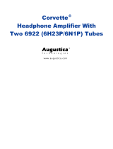
Figure 4- M-RK Vehicular Charger Block Diagram

LBI-38936
16
facilitate servicing the Vehicular Charger. The Test
Adaptor is used to simulate actual battery pack conditions
and determine if the charger is working properly.
Simulations include cold battery pack, battery pack
normal range temperature, and hot battery pack.
Information pertinent to construction of the Test Adaptor
is found in the last section of this manual.
DISASSEMBLY PROCEDURE
1. Remove radio from charger (UDC in released
position).
2. Remove charger from vehicle.
3. Remove the Charger Top Cover.
a. Remove three Phillips head screws from the
bottom of the charger near the back edge.
b. Next, remove the sliding radio cover
(polycarbonate resin) section of the top cover.
This cover slides down toward the back of the
charger after the bottom edge is raised to escape
small locking ridges in the mating plastic piece.
Free the sliding cover by inserting the tip of a flat
blade screw driver in the small notch at the back
center of the cover and gently pry to lift the cover
over the ridges and slip it back about 3/8 inches.
From this position the sliding portion of the
cover can be lifted straight up and off.
c. The remainder of the cover can now be tilted up
from the back edge, rotating around the front
lower edge of the charger, until it is
approximately 45° from horizontal, and then
slipped forward and off. The front panel with all
switches and indicators remains attached to the
base casting.
4. Remove the four (4) Phillips head screws from the RF
protective shield covering the circuit components.
ADJUSTMENT PROCEDURE
The only adjustment to the M-RK vehicular charger
is the setting of dip switches S3 and S5. The factory DIP
switch settings for both the Part 1 and Part 2 chargers is as
follows:
SW3 1 2 3 4 5 6 7
Part 1 ON OFF ON ON ON OFF OFF
Part 2 ON OFF ON ON ON OFF OFF
SW5 1
Part 1 OFF
Part 2
The M-RK radio is designed with Rx an Tx serial
data ports the UDC. This allows the radio to be remotely
controlled. The Part 2 vehicular charger contains remote
control logic (IC10) which buffers these data signals to
IEE-485 levels that are compatible with the ORION
control units. M-RK software is written so that this remote
control operation is enabled when the 3160 ohm
resistor(SW3-5) is connected to the UDC sense pin. In
this configuration, the ORION control unit assumes full
control of radio operation including remoting of the M-
RK display information.
The following switch settings are required for several
operational modes. Any switch settings not defined below
cannot be used and must be avoided.
SWITCH NUMBERS
1234 567
Ignition A+ - Inhibited
ON OFF X X X X X
Ignition A+ - Enabled
OFF ON X X X X X
Option Switch - Inhibited
XXXONXXX
Option Switch - Enabled
X X X OFF X X X
Display Invert - Normal
X X X X ON OFF OFF
Display Invert - Inverted
X X X X OFF ON X
ORION Control Head - inhibited
X X ON OFF OFF OFF OFF
ORION Control Head - Enabled
X X OFF OFF OFF OFF OFF
X -DON'T CARE

LBI-38936
17
BATTERY PACK TEST SIMULATOR CONSTRUCTION
This test battery pack simulator must be adapted to a dummy battery pack which will fit into the sleeve of the charger
under test. The dummy battery pack should have a mechanism to operate the microswitch in the charger sleeve so that charge
currents for short and long batteries can be measured.
8.7 Volt
POWER SUPPLY
+
2200 uF
2 Ohms
50 Watts
(+)
AMMETER
0-3 AMPS.
50 OHMS
5%
(+) BATTERY
THERMISTOR
GROUND
Figure 5 - Battery Pack Test Simulator
TEST PROCEDURE
1. With the vehicular charger connected to the normal 13.8 Vdc supply, plug the test circuit (adaptor) into the charging
sleeve. When inserted, the yellow LED
"CHRG"
indicator must light.
2. Calibrate the adaptor by setting the 8.7-volt supply to 8.7 Vdc ± 0.1 Vdc. the ammeter on the adapter must read the
following:
SHORT BATTERY
CHARGE CURRENT
LONG BATTERY
CHARGE CURRENT
1170 to 1430 mA 1710 to 2090 mA

LBI-38936 IC DATA
18
Linear: Switching Regulator IC1, IC7
(FUJITSU MB3759PF OR NEC
µ
PC494GS)
Regulator Auxiliary Function IC3
(FUJITSU MB3773PF)
Linear: +6-Volt Regulator IC8
(JRC NJM78L06T OR NEC
µ
PC78L06T)
Digital: Quad Bilateral Switch IC5
(HITACHI HD74HC4066FP OR
NEC
µ
PD74HC4066GS)

IC DATA LBI-38936
19
Linear: Operational Amplifier IC9
(NEC
µ
PC358G2 OR HITACHI HA17904FP)

LBI-38936 PARTS LIST
20
VEHICULAR CHARGER MAIN BOARD
344A4616P1 (PCB1)
Issue 1
SYMBOL PART NUMBER DESCRIPTION
PCB2 Vehicular Charger LED Board
- - - -CONNECTORS- - - -
CN7 6-Conductor With Leads.
- - - - - - -LEDS- - - - - - - -
LED1 Yellow, Rectangular.
LED2 Green, Rectangular.
LED3 Red, Rectangular.
PCB3 Microphone Connector
PCB4 Universal Devices Connector
- - - -CAPACITORS- - - -
C1
NOTE:
Parts
listed are for
Ceramic: 0.1 µF ±10%, 25 V.
C2 reference only.
Electrolytic, aluminum: 330 µF, 25
V.
C3
Electrolytic, aluminum: 1500 µF, 25
V.
C4
Ceramic: 0.1 µF ±10%, 25 V.
C5
Electrolytic, aluminum: 220 µF, 25
V.
C6
Ceramic: 0.1 µF ±10%, 25 V.
C7 Ceramic: 470 pF ±5%, 50 V.
C8
Ceramic: 0.1 µF ±10%, 25 V.
C9
Electrolytic, aluminum: 4.7 µF, 50
V.
C10
thru
C13
Ceramic: 0.1 µF ±10%, 25 V.
C14
Electrolytic, aluminum: 1500 µF, 16
V.
C15
and
C16
Ceramic: 0.1 µF ±10%, 25 V.
C17
and
C18
Ceramic: 0.01 µF ±10%, 50 V.
C19
Electrolytic, aluminum: 100 µF, 25
V.
C20
Electrolytic, aluminum: 10 µF, 25 V.
C21
Ceramic: 0.1 µF ±10%, 25 V.
C22
Electrolytic, aluminum: 1 µF, 25 V.
C23
Ceramic: 0.1 µF ±10%, 25 V.
C24
and
C25
Ceramic: 100 pF ±5%, 50 V.
C26
and
C27
Ceramic: 0.1 µF ±10%, 25 V.
C28
Electrolytic, aluminum: 1 µF, 25 V.
C29
Ceramic: 0.1 µF ±10%, 25 V.
C30
Electrolytic, aluminum: 1 µF, 25 V.
C31
and
C32
Ceramic: 0.1 µF ±10%, 25 V.
* COMPONENTS ADDED, DELETED OR CHANGED BY
PRODUCTION CHANGES.
SYMBOL PART NUMBER DESCRIPTION
C67
thru
C75
Ceramic: 0.001 µF ±10%, 50 V.
C78
thru
C80
Ceramic: 0.001 µF ±10%, 50 V.
C101
Ceramic: 0.1 µF ±10%, 25 V.
C102
- - - - -DIODES- - - - -
D1 Suppresser.
D2 Silicon.
D3 Silicon, zener.
D4 Silicon.
D5
and
D6
Silicon.
D7 Silicon: Dual diodes, common
cathode.
D8 Silicon: Dual diodes, common
cathode.
D9 Silicon: Dual diodes in series.
D10
and
D11
Silicon: zener.
D15 Silicon: Dual diodes, common
cathode.
D18 Silicon: Dual diodes, common
cathode.
D22 Silicon, zener.
- - - - -INDUCTORS- - - - -
L1 Inductor.
- - -TRANSISTORS- - -
Q1 Silicon, N-channel MOSFET.
Q2 Silicon, PNP.
Q3 Silicon, PNP (with bias resistors).
Q4 Silicon, PNP.
Q5 Silicon, NPN.
Q6 Silicon, PNP (with bias resistors).
Q7 Silicon, PNP.
Q8 Silicon, PNP (with bias resistors).
Q9 Silicon, PNP.
Q20 Silicon, NPN.
- - - -CONNECTORS- - - -
CN1 DB-25 Connector
CN3 6-pin Solder in place
INTEGRATED CIRCUITS
IC1 Linear: Switching Regulator.
IC2 Linear: +5-Volt Regulator.
IC3 Regulator Auxiliary Function
IC4 Digital: Microcontroller.
IC5 Digital: Quad Bilateral Switch.
- - - - RESISTORS- - - -
R1 Metal film: 100 ohms ±5%, 1/10
W.
R2 Metal film: 4.7 ohms ±5%, 1/10
W.
Continued
/