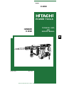
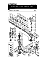
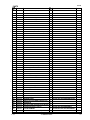
Hitachi H 45SR Technical Data And Service Manual
- Category
- Rotary hammers
- Type
- Technical Data And Service Manual
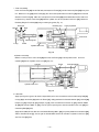
Hitachi H 45SR is a high-performance electric hammer designed for demanding demolition and chiseling tasks. With its powerful 12.5 J impact energy, it delivers excellent chipping and demolishing performance, outperforming similar products by 30-40%. Despite its power, the H 45SR operates with low vibration and noise levels, ensuring user comfort during extended use. The self-chiseling feature provides a smooth and efficient operation, reducing operator fatigue.
Hitachi H 45SR is a high-performance electric hammer designed for demanding demolition and chiseling tasks. With its powerful 12.5 J impact energy, it delivers excellent chipping and demolishing performance, outperforming similar products by 30-40%. Despite its power, the H 45SR operates with low vibration and noise levels, ensuring user comfort during extended use. The self-chiseling feature provides a smooth and efficient operation, reducing operator fatigue.


-
 1
1
-
 2
2
-
 3
3
-
 4
4
-
 5
5
-
 6
6
-
 7
7
-
 8
8
-
 9
9
-
 10
10
-
 11
11
-
 12
12
-
 13
13
-
 14
14
-
 15
15
-
 16
16
-
 17
17
-
 18
18
-
 19
19
-
 20
20
-
 21
21
-
 22
22
-
 23
23
-
 24
24
-
 25
25
-
 26
26


Hitachi H 45SR Technical Data And Service Manual
- Category
- Rotary hammers
- Type
- Technical Data And Service Manual
Hitachi H 45SR is a high-performance electric hammer designed for demanding demolition and chiseling tasks. With its powerful 12.5 J impact energy, it delivers excellent chipping and demolishing performance, outperforming similar products by 30-40%. Despite its power, the H 45SR operates with low vibration and noise levels, ensuring user comfort during extended use. The self-chiseling feature provides a smooth and efficient operation, reducing operator fatigue.
Ask a question and I''ll find the answer in the document
Finding information in a document is now easier with AI
Related papers
-
Hitachi H 60MC Handling Instructions Manual
-
-
-
-
-
Hitachi H65SD2 User manual
-
-
-
-
Other documents
-
 JC Hammer EW0050 Installation guide
-
Ohlins 18108-01 Mounting Instruction
-
 Foundation Armor SX5000LX405GAL Specification
-
 King Arthur's Tools 10025 Specification
-
 EZPole EZL21B Installation guide
-
Makita HM1317CB Datasheet
-
Makita HM1317C Datasheet
-
REXON DH410R Owner's manual
-
Makita HR2811FT Datasheet
-
Makita HR2811F Datasheet


