Page is loading ...

ESSNA
ESSNA
MORE PEOPLE BUY
AND
FLY
CESSNA AIRPLANES
TAKE
YOUR
CESSNA
HOME
THAN
ANY
OTHER
MAKE
1970
CESSNA
AIRCRAFT
COMPANY
WUORLEDR'S
LAR
ESNERROL
OWNER'S
'N
WICHITA, KANSAS
AVIATION
AIRCRAFT
SINCE
1956 MANUAL

PERFORMANCE
-
SPECIFICATIONS
SERVICING REQUIREMENTS
Skywagon 180
*
GROSSWEIGHT
.........
..
.......
28001bs
FUEL·
SPEED:
Top
Speed at Sea
Level
. . . . .
. . . . . . .
. . .
170
mph
AVIATION
GRADE
--
80/87 MINIMUM
GRADE
Cruise,
75%
Power at 6500 ft
. .
. . . . . .
. . . .
162 mph
CAPACITY EACH
STANDARD TANK
--
32. 5 GALLONS
RANGE:
CAPACITY
EACH
LONG
RANGE
TANK
--
42. O
GALLONS
Cruise,
75%
Power
at 6500 ft
.
. . . . . . .
.
.
. .
695 mi
60 Gallons, No
Reserve
4.
3
hrs
162
mph
ENGINE OlL:
Cruise,
75%
Power
at
6500 ft
.
.
.
. . . . .
.
.
.
.
925 mi
AVIATION GRADE
--
SAE
50 ABOVE
40°
F.
79 Gallons, No
Reserve
2 ph
SAE
10W30 OR SAE
30
BELOW
40°
F.
Optimum
Range
at
10, 000 ft . . .
. . . . . . .
.
. . 925 mi
(MULTI-VISCOSITY
OIL
WITH
A
RANGE
OF
SAE 10W30
60 Gallons, No
Reserve
7. 6
hrs
IS
RECOMMENDED
FOR IMPROVED STARTING
IN
COLD
121 mph
WEATHER. DETERGENT
OR
DISPERSANT
OIL,
CON-
Optimum Range
at 10,000 ft
. . .
. . . . . .
.
.
. .
1215 mi
FORMING
TO
CONTINENTAL
MOTORS
SPECIFICATION
79 Gallons, No
Reserve
10.0 hrs
MHS-24A,
MUST
BE
USED.)
121 mph
CAPACITY
OF
ENGINE
SUMP
--
12 QUARTS
RATE
OF CLIMB AT
SEA
LEVEL
. .
. .
.
.
. .
.
. . .
1090 fpm
SERVICE
CEILING
.
. . .
.
.
.
. . . . . . . .
.
. . .
19,
600 ft
(DO
NOT
OPERATE
ON LESS
THAN
9 QUARTS.
TO
TAKE-OFF:
MINIMIZE LOSS
OF
OIL THROUGH
BREATHER, FILL
Ground Run
. .
. . . . . . . . . . . . . .
.
. . .
625
ft
TO
10 QUART LEVEL
FOR
NORMAL
FLIGHTS
OF LESS
Total
Distance Over
THAN
3 HOURS.
FOR EXTENDED FLIGHT, FILL TO
50-Foot
Obstacle
.
. . . . . .
. .
. . . .
.
. .
.
1205
ft
12 QUARTS.
IF OPTIONAL
OIL
FILTER IS
INSTALLED,
LANDING:
ONE ADDITIONAL
QUART
IS
REQUIRED
WHEN
THE
GroundRoll . . .
.
.
. . . . .
. .
. . . .
.
. . .
480ft
FILTERELEMENTISCHANGED.)
Total
Distance
Over
50-FootObstacle.................
1365ft
STALL
SPEEDS:
HYDRAULIC
FLUID:
Fla DU
Power7OffOff
.
p
MIL-H-5606
HYDRAULIC
FLUID
EMPTY
WEIGHT (Approximate)
. . .
.
. . . . .
. . . .
1545
lbs
USEFULLOAD(Approximate).
. .
.
. . . . . .
. . . .
12551bs
OXYGEN:
BAGGAGE
(Total Capacity)
. .
. . .
.
. . . . .
. . . .
400 lbs
WING LOADING: Pounds/Sq Foot
. .
. .
.
. .
.
.
.
. .
16.1
AVIATOR'S
BREATHING
OXYGEN
--
SPEC.
NO.
MIL-O-27210
POWER
LOADING: Pounds/HP
.
. .
. . . . . .
. . . .
12.2
MAXIMUM
PRESSURE
--
1800
PSI
AT
70°F.
FUEL CAPACITY: Total
(CYLINDER
TEMPERATURE
STABILIZED
AFTER
FILLING)
Standard Tanks
. .
.
. . . . .
.
.
.
. . .
.
. . .
65
gal.
REFER
TO PAGE
7-10
FOR FILLING BRESSURES.
Optional Long Range
Tanks
.
. .
. . . . . .
.
. . .
84
gal.
OILCAPACITY: Total . .
. . . . . ..
.
.
. . .
. . .
12qts
TIRE PRESSURE:
PROPELLER: Constant
Speed
(Diameter) . . . . .
.
. . . 82
inches
ENGINE:
MAIN
WHEELS
--
30 PSI
ON 6.
00
×
6
TIRES
Continental Engine .
.
. . . . .
.
. .
.
. .
.
.
. .
O-470-R
23
PSI ON 8.
00
×
6
TIRES
(OPTIONAL)
230
rated HP at
2600
RPM
TAIL
WHEEL
--
55
PSI TO 65 PSI MAXIMUM
(2300 LBS
TO
2800
LBS NORMAL
OPERATING
LOADS)
*
This
rnanual covers operation of the Skywagon
180
which is certificated
as Model
180El
under
FAA
Type
Certificate No. SA6.
D765-13-RAND-1,000-12|69

WARRANTY
CONGRATULATIONS
. . . .
. .
The Cessna Aircraft
Company ("Cessna") warrants each new aircraft
manufactured
Welcome
to the
ranks of Cessna Owners!
Your
Cessna
has been designed
by
it and such new
aircraft
equipment,
accessories
and
service parts
as are
sold
and
constructed
to
give you the
most in
performance,
economy,
and
com-
through its
Commercial
Aircraft
Marketing Division
to be free
from
defects in
material
fort. It
is
our desire
that you
will find flying
it,
either
for business or
and
workmanship under normal use and service
for a period of six (6) months after
delivery
to the
original retail purchaser or first
user in the case of
aircraft, aircraft
pleasure,
a
pleasant and
profitable experience.
equipment
and accessories (except
Cessna-Crafted
Electronics as herein
defined) and
service
parts
therefor,
and
for
a period
of one (1) year after such
delivery in the case
This
Owner's Manual
has been
prepared
as a
guide to
help
you get the
of
Cessna-Crafted
Electronics
(which term
includes
all
communication, navigation
most
pleasure
and
utility
from
your
Skywagon
180.
It
contains
informa-
and
autopilot systems
bearing
the name
"Cessna",
beginning at the
connecuon
to
the
tion
about your Cessna's equipment, operating
procedures,
and
perform-
aircraft
electrical system
(bus bar) and
including
"black
boxes",
antennas,
micro-
phones, speakers
and other components and
associated
wiring
but
excluding gyro
in_
ance;
and suggestions for its
servicing
and care. We
urge you to read
it
struments used
in connecuon with autopilot and
navigation systems) and service
parts
from
cover
to
cover,
and
to
refer to it frequently.
therefor.
Cessna's
obligation
under this
warranty is limited
to repairing or
replacing,
at its
Our interest
in your
flying
pleasure
has
not
ceased
with your purchase
of
option,
any part
or parts
which, within
the applicable
six
(6)
or twelve
(12) months
a Cessna.
World-wide,
the
Cessna Dealer
Organization backed
by the
period
as
above set
forth, shall
be returned
transportation
charges prepaid to
Cessna
Cessna
Service
Department
stands ready
to
serve
you.
The
following
at
Wichita,
Kansas, or to
any
Cessna
appointed
or Cessna
Distributor appointed
dealer
services are
offered
by most
Cessna
Dealers:
authorized
by
such
appointment to
sell
the
aircraft, equipment, accessories
and service
paarts
1
tthe
typebinevolvhedsa
wh
heupon
examination
shyal
diLcd
issenoo
Ceesasbnlaisshesatisr
FACTORY
TRAINED
PERSONNEL
to
provide
you with courteous
replacements.
Replacements are
warranted
for the remainder
of the
applicable six
(6)
expert
service.
or
twelve
(12) months
original
warranty period.)
The
repair or replacement
of
defec-
tive parts
under
this
warranty will be
made
by
Cessna
or the
dealer
without
charge for
FACTORY APPROVED SERVICE EQUIPMENT
to provide you
parts, or
labor for
removal,
installation
and/or actual
repair of such defective
parts·
with the most
efficient and
accurate
workmanship
possible.
(Locations
of such
dealers will be
furmshed
by
Cessna on
request.)
The provisions
of this
warranty
do not
apply to
any
aircraft,
equipment, accessories
A
STOCK OF GENUINE
CESSNA SERVICE
PARTS
on
hand
(including
Cessna-Crafted
Electronics) or service parts therefor
manufactured or
sold
when
you need
them.
by
Cessna which
have been subject to
misuse, negligence, or accident, or which
shall
have been
repaired or altered outside
of Cessna's
factory
in
any way
so
as in.the
THE
LATEST
AUTHORITATIVE
INFORMATION FOR
SERV-
judgment
of Cessna to
affect
adversely
its
performance, stability
and
reliability, nor
ICING CESSNA AIRPLANES
since
Cessna
Dealers
have all
to normal maintenance
services (such
as engine tune up,
cleaning,
control
rigging
'
brake and other
mechanical
adjustments,
maintenance
inspections,
etc.) and the
of the
Service
Manuals and
Parts
Catalogs,
kept
current by
replacement of
service items (such
as spark
plugs, brake
linings,
filters, hoses,
Service Letters
and
Service News
Letters,
published
by
belts,
tires,
etc.)
made
in
connection
with such
services or
required
as
maintenance,
CeSSna Aircraft Company.
nor
to
normal deterioration
of
soft trim
and
appearance items
(such
as
paint,
uphol-
stery,
rubber-like
items, etc.)
due to
wear and
exposure.
We urge
all Cessna owners
to use
the Cessna
Dealer
Organization
to
the
THIS WARRANTY
IS
EXPRESSLY
IN LIEU
OF ANY ØrHER
WARRANTIES,
EXPRESSED
ÎulleSt.
OR
IMPLIED
IN
FACT
OR
BY LAW,
INCLUDING
ANY
IMPLIED
WARRANTY
OF
MERCHANTABILITY
OR
FITNESS
FOR A
PARTICULAR
PURPOSE, AND OF ANY
A
current
Cessna Dealer
Directory
accompanies your new
airplane. The
URREOW AATSOOEN
OERRLRY
E
OONNOF
TH
MAONFUCFEASCSNUAREOAA
YOONRESAOFLEA
Directory
is revised
frequently,
and a current copy
can be
obtained
from
THE
USE OF SUCH
AIRCRAFT
PRODUCTS,
INCLUDING
LIABILITY
FOR
CONSE_
your Cessna Dealer. Make your Directory
one
of
your
cross-country
QUENTIAL
OR SPECIAL
DAMAGES, AND CESSNA
NEITHER ASSUMES
NOR
AU-
flight
planning
aids;
a warm welcome awaits you
at
every
Cessna Dealer.
THORIZES
ANYONE
TO ASSUME FOR
IT ANY
OTHER
OBLIGATION
OR LIABILITY
IN
CONNECTION WITH
SUCH AIRCRAFT
PRODUCTS.
i

7
-9"
MAX.
*
Maximum
height of aircraft
10
10
with an
optional
flashing
beacon
installed.
PRINCIPAL
I
DIMENSION
numuuluullIluunulluut
©
©
35
-10"
82"
7
.8"
ii

Spark
Plugs,
5-9
data,
6-3
Speed,
inside front
cover
maximum
performance,
1-3
Spins,
2-11
normal,
1-3
Split
Bus
Contactor,
2-4
Taxiing,
2-7
Stabilizer
Jackscrews,
5-10
Throttle,
1-6,
2-2
Stall
Speeds, inside
front cover,
Tie-Down
Diagram,
4-9
Sta61
,
2-10
T
Down Pr
ced nre,de
lack
cover
TABLE
OF
CONTENTS
Starter,
2-4
True
Airspeed
Indicator,
7-16
Starter
Contactor,
2-4
_____
Pago
Starting
Engine,
1-2,
2-6,
2-12
Static
Pressure Alternate
Source
SECTION I
-
OPERATING
CHECK
LIST
........
1-1
Valve,
7-4
U
Storage,
Flyable,
5-5
SECTION ll
-
DESCRIPTION AND
Stowable Rudder
Pedals,
7-13
Useful
Load,
inside
front cover
control,
1-6
OPERATING
DETAILS
...----------
2-1
Strainer, Fuel,
2-2,
5-7,
5-9
Suction Relief Valve
Inlet
Screen,
SECTION
III
-
EMERGENCY
PROCEDURES __...
3-1
5-9
Sump
Drain
Plugs,
Fuel
Tank, 5 9
SECTION IV
-
OPERATING
LIMlTATIONS........
4-1
Surfaces, Vacuum
System Air
Filter,
5-10
aluminum,
5-2
Vacuum System Oil Separator,
5-9
SECTION
V
-
CARE OF
THE
AIRPLANE....--..
5-1
painted,
5-3
Valve,
Fuel
Selector,
2-2
Switches,
Electrical,
1-6
OWNER
FOLLOW-UP
SYSTEM
................
5-11
System,
eleletr
al,
2-3
W
SECTION VI
-
OPERATIONAL
DATA..............
6-i
he
nros
entil2at15ng
and
Weight,
SECTION
VII-
OPTIONAL SYSTEMS....--........
7-1
oil
dilution,
7-2
empty, inside
front cover
owner follow-up,
5-11
gross,
inside front cover
ALPHABETICAL
INDEX....---.....----...........
Index-1
oxygen,
7-6
Weight and
Balance,
4-3
loading
graph,
4-6
moment
envelope,
4-7
sample
loading
problem,
4-5
Wheel
Bearings,
Main,
5-10
Windshield and
Windows,
5-2
Table
of
Contents,
iii
Wing Leveler,
7-14
Tachometer,
1-6,
4-3
emergency procedures,
7-15
Tail
Wheel
Bearings,
5-9
operating check
list,
7-14
Tail
Wheel Pivot,
5-9
operating notes,
7-15
Take-Off,
inside
front cover,
1-3,
Wing Loading,
inside front
cover
2-8
Wing
Tanks,
2-2,
7-1
before,
1-2,
2-7
Winterization
Kit,
7-1
iii
Index-6

oil
dipstick calibrations,
5-8
5
oil
filler,
5-7
oil
filter,
5-9
Quick-Drain
Valve, Oil,
7-17
oil pressure
gage,
1-6,
4-3
oil pressure
switch,
2-4
oil
quick
-drain
valve,
7
-17
6
oil
screen,
5-9
---
4
¯
¯,
oil temperature
gage,
1-6,
4-2
R
Operation
Limitations,
Engine,
4-2
Operation,
Cold
Weather,
2-12
Radios,
1-6
.2 Operations, Authorized,
4-1
Radio
Selector
Switches,
1-6,
7-4
Optimum
Cruise
Performance,
2-10
autopilot-omni
switch,
7-5
Optional Instrument
Space,
1-6
operation,
7-4
EXTERIOR
Note
Optional Radio
Space,
1-6
speaker-phone
switches,
7-5
INSPECTION
ede
al
Owner Follow-Up
System,
5-11
transmitter
selector
switch,
spectior.
Incoldweather,
remove
Oxygen
System,
7-6
7-4,
7-5
c'e",r""n?
Ice
a
neofa"d°"'
cylinder,
5-8,
5-10
Range,
inside front cover
t"c°on'rii
« c
"iane s
duration
calculation,
7-9
Rate
of
Climb, inside front cover
ternal
accumulations of
ice or
de-
duration
chart,
7-7
data,
6-3
b
sck
pe
onofhalll e
nd
Îiller
Valve,
5-8
Regulator,
2-4
make sure a
flashlight is
available
Operation,
7-6
Removable Cabin
Door,
2-6
servicing,
7-9, inside
back
Reverse
Polarity
Contactor,
2-4
cover
Rough
Engine Operation
Or Loss of
Power,
3-2
.
low oil pressure,
3-3
a.
Remove control
wheel lock.
b.
Check
propeller and spinner for mcks
and
b.
Check
igmtion
switch "OFF."
security,
and
propeller for oil leaks.
magneto malfunction,
3-2
c.
Turn on
master
switch and check fuel
c.
Check carburetor air
filter for restrictions by
quantity indicators,
then
turn
master
dust or other foreign
matter.
Spark plug fouling,
3-2
switch
"OFF."
d.
Check oil level. Do not
operate with less
Rudder
Pedals,
Stowable
7-13
d. Check fuel
selector valve
handle in
than nine
quarts. Fill to
twelve quarts
"BOTH
ON" position,
for extended flight.
COntrol,
1-6
e.
Check baggage
door for security,
e, Before
first flight of
day
and
after
each
.
refueling,
pulloutstrainer drainknobfor
Pamted
Surfaces,
5-3
a.
Remove rudder
gust
lock,
if installed,
about four seconds
to clear
fuel strainer of
Parkin
Brake Handle
1-6
b.
Disconnect tail
tie-down.
possible water and sediment.
Check
strainer
c. Check
tail wheel tire
for proper
inflation,
drain closed. If
water is
observed,
there is
POTÎOrmance, Cruise, 2-9,
6-4
d. Check
control surfaces
for freedom
of a
possibility that the fuel tank
sumps contain
'
movement and security,
water. Thus, the fuel tank sump
drain
plugs
6-5,
6-6
a. Check
control
surfaces for free and
correct
and
Ikselrectorpdrain plug should be removed
POTÎOrmance
-Specifications, inside J
movement and security.
ÎTORÉ
COVer
a.
Remove pitot tube
cover,
if installed,
4
a.
Disconnect wing
tie-down.
and check
pitot tube openîng for stoppage.
Phone
Jack,
1-6
Sample
Loading Problem,
4-5
C f
ta
e
nLopeninpgroprer
i
aag
b. Check
stall
warning
vent opening for
stoppage.
POWer
Loading,
inside front cover
Securing Aircraft,
1-5
d. Viel
111ercheck
feuel quantity, then
check
Same
as
3
PTOCRUÉÎOnary Landing With Engine
Selector
Valve,
Fuel,
2-2
Power,
3-3
Service
Ceiling,
inside front cover
5
a. Insp de
o a
f
re sp agce (o
es dpees
Same as
Primer, Engine,
1-6,
2-2
Servicing and Lubrication
Principal
Dimensions, ii Procedures,
5-7
Propeller,
inside front cover
Servicing Intervals Check List,
5-9
care,
5-3
Servicing Requirements,
inside
Figure
1-1.
Propeller Control
Knob,
1-6
back cover
Index-5

Maneuvers
-
Normal
Category,
4-1
Manifold
Pressure
Gage,
1-6,
4-3
Ignition/Starter Switch, 1-6,
2-4
Map
Compartment,
1-6
Inspection
Diagram,
Exterior, iv
Map
Light, Control
Wheel,
2-3
Inspection
Service-Periods,
5-5
Marker Beacon
Indicator
Lights
Instrument
Markings, Engine,
4-2
and
Switch,
1-6
OPERATING
CHECK LIST
Instrument
Panel,
1-6
Master
Cylinders,
Brake,
5-9
Interior Care,
5-4
Master Switch, 1-6,
2-3,
2-4
Internal
Cabin
Dimensions,
4-10
Maximum
Glide,
6-8
Maximum
Performance
Climb,
1-4
One
of the
first steps in
obtaining
the
utmost
performance
service,
Maximum Performance
Take-Off,
and flying
enjoyment from
your Cessna is to familiarize yourself
with
your
1-3
airplane's
equipment,
systems, and
controls.
This can
best
be
done
by
L
Maximum
Rate-of-Climb
Data,
6-3
reviewing
this equipment while
sitting
in the
airplane.
Those items
whose
Microphone,
1-6
function and
operation are not obvious are covered in Section II.
.
.
Mixture
Control
Knob,
1-6,
2-2
Landing,
inside front
cover,
2-11
after,
1-5
Moment
Envelope,
Center of
Section
I
lists,
in Pilot's Check List
form, the steps necessary
to
balked,
1-5,
2-11
Gravity,
4-7
operate
your
airplane
efficiently
and
safely. It is not a
check list in its
before
1-4
Mooring
Your Airplane,
5-1
true form as it is
considerably longer,
but it does cover briefly àll of the
distance
table,
6-7
points
that you should know for
a
typical
flight.
normal,
1-5
Let-Down,
1-4
The
flight and
operational
characteristics of
your airplane are normal
Leveler,
Wing,
7-14
in
all
respects.
There are no "unconventional"
characteristics
or
opera-
emergency
procedures,
7-15
tions that need to
be mastered.
All
controls
respond
in
the
normal
way
operating
check list,
7-14
within
the
entire
range of
õperation. All airspeeds
mentioned in Sections
operating notes,
7-15
Non-Congealing
Oil Cooler,
7-1
I, H and HI are indicated
airspeeds. Corresponding
calibrated airspeeds
Limitations, Airspeed,
4-2
Normal
Category
Maneuvers,
4-1
may
be
obtained
from the
Airspeed Correction Table
in Section VI.
Limitations,
Engine
Operation,
4-2
Normal Chmb,
1-3
Line Drain
Plug, Fuel,
5-9
Normal Landing,
1-5
. .
Normal
Take-Off,
1-3
oaa
in
A
rlan
eentfro
8cover
BEFORE
ENTERING
THE
AIRPLANE.
Loading
Graph,
4-6
Loading Problem, Sample,
4-5
(1)
Make an exterior inspection in accordance
with
figure
1-1.
Long Range Fuel
Tanks,
7-1
Lubrication and
Servicing
Procedures,
5-7
Oil
System,
BEFORE
STARTING THE
ENGINE.
capacity,
inside
covers
dilution
switch,
1-6
(1) Seats
and
Seat
Belts
--
Adjust and
lock.
dilution system,
7-3
(2) Brakes
--
Test and set.
M
dilution
table,
7-3
(3)
Radios
and Electrical
Equipment
--
"OFF."
oil,
5-7, 5-8,
5-9, inside back
(4)
Fuel
Selector Valve
--
"BOTH ON.
"
Magnetic
Compass,
1-6
cover
(5) Wing Flaps
--
Check
all
positions.
Magnetos,
2-4
oil cooler,
non-congealing,
7-1
(6)
Cowl
Flaps
--
"OPEN.
"
(Move
lever
out
of locking
detent to
Main Wheel
Bearings,
5-10
oil
dipstick,
5-8
reposition.)
Index-4
1-1

STARTINGEN GI
N
E.
Emergency
Landing without
Engine Fuel
Quantity
Indicators,
1-6,
4-2
Power,
3-3
Fuel
System,
2-1
(1)
Master
Switch
--
"ON."
Emergency
Let-Downs
Through
capacity,
inside
covers
(2)
Carburetor
Heat
--
Cold.
Clouds,
3-5
carburetor,
2-2
(3)
Mixture
--
Rich.
Empty
Weight, inside front
cover fuel
quantity
indicators,
1-6,
(4) Primer
--
As required.
Engine,
inside front
cover
4-2
(5)
Propeller
--
High RPM.
before
starting,
1-1
line
drain
plug,
5-9
(6)
Throttle
--
Cracked
(one-half
inch).
instrument
markings,
4-2
mixture
control
knob,
1-6,
2-2
(7)
Propeller Area
--
Clear.
oil, inside
back
cover
primer, 1-6,
2-2
(8)
Ignition Switch
--
"START" (hold until
engine
fires,
but not
oil,
dipstick,
5-8
quick-drain
valve
kit,
7-16
longer
than 30
seconds),
oil
filler,
5-7
schematic,
2-2
(9)
Ignition Switch
--
Release to
"BOTH" (immediately
after
engine
oil
filter,
5-9
selector
valve,
2-2
fires).
oil
screen,
5-9
strainer, 2-2,
5-7,
5-9
operation
limitations,
4-2
tank
fillers,
5-7
NOTE
primer,
1-6
2-2
tank
sump drain
plugs,
5-9
starting, 1-2,
2-6,
2-11
throttle, 1-6,
2-2
If engine has
been
overprimed,
start
with throttle
open
Engine
Instrument
Markings,
4-2
vent,
2-2
1/4
to
1/2
full
open. Reduce
throttle to idle when engine
Excessive
Rate
of Electrical
wing tanks, 2-2,
7-1
fires.
Charge,
3-1
Fuel
Tanks, Long
Range,
7-1
Executing
180°
Turn in
Clouds,
3-5
Fuses
and
Circuit
Breakers,
1-6,
NOTE
Exterior
Inspection
Diagram,
iv
2-3,
2-4
After
starting,
check for oil pressure
indication within
30 seconds
in normal temperatures
and 60
seconds
in
cold
temperatures.
If no indication
appears,
shut off
engine and
investigate.
F
G
File,
Aircraft,
5-6
Glide,
Maximum,
6-8
Filler,
Oil,
5-7
Graph,
Loading,
4-6
Filter,
Oil,
5-9
Gross
Weight,
inside front
cover
BEFORE
TAKE-OFF. Fires,
3-6
Ground
Handling,
5-1
electrical
fire
in
flight,
3-6
Ground
Service
Plug
Receptacle,
(1) Parking
Brake
--
Set.
engine fire
in
flight,
3-6
2-4,
7-2
(2) Fuel
Selector Valve
--
"BOTH
ON.
"
Flashing
Beacon,
2-5
(3)
Flight
Controls
--
Check
for free
and correct movement.
Flight Hour
Recorder,
2-4
(4)
Stabilizer and Optional
Rudder
Trim
Control Wheels
--
Take-off
Flight
in
Icing
Conditions,
3-7
settings.
Flight
Instruments,
1-6
(5)
Cowl Flaps
--
Check full
"OPEN."
Flyable
Storage,
5-5
H
(6)
Throttle Setting
--
1700
RPM.
Forced
Landings,
3-3
(7)
Magnetos
--
Check (50 RPM
maximum
differential
between
mag-
ditching,
3-4
Handling Airplane
on
Ground,
5-1
netos).
emergency
landing without
Heating,
Ventilating and
Defrosting
(8)
Propeller
--
Cycle
from high to
low RPM;
return to high
RPM
engine
power,
3-3
System,
2-5
(full
in).
precautionary
landing
with
Hour
Recorder, Flight,
2-4
(9)
Carburetor Heat
--
Check
operation.
engine
power,
3-3
Hydraulic
Fluid, inside
back cover
1-2
Index-3

Cold
Weather
Fquipment,
7-1
Disorientation In
Clouds,
3-4
(10) Engine
Instruments
--
Check.
Cold
Weather
Operation,
2-12,
emergency
let-downs
through
(11) Suction
Gage
--
Check
(4.6
to
5.4
inches
of
mercury).
2-13
clouds,
3-5
(12) Ammeter
--
Check.
starting,
2-12
executing
a
180°
turn
in
(13)
Throttle
--
Closed (check
idle).
Compass
Correction
Card,
1-6
clouds,
3-5
(14)
Flight
Instruments
and Radios
--
Set.
Compass,
Magnetic,
1-6
recovery
from
spiral
dive,
3-6
(15)
Optional
Autopilot
or Wing Leveler
--
"OFF.
"
Compartment,
Door,
Removable
Cabin,
2-6
(16)
Cabin
Doors and Windows
--
Closed
and
locked.
aft
baggage,
2-6
Drain Plug, Fuel
Line,
5-9
(17)
Parking
Brake
--
Release.
map,
1-6
Drain
Plugs,
Fuel
Tank
Sump,
5-9
Control
Wheel
Map
Light,
2-5
Correction
Table,
Airspeed,
6-2
Cowl
Flap
Handle
1-6
Cruise
Performance,
6-4,
6-5,
TAKE-OFF.
6-6
E
optimum,
2-10
NORMAL
TAKE-OFF.
Cruising, 1-4,
2-9
Economy Mixture
Indicator,
7-11
Cylinder
Head Temperature
operating
instructions,
7-11
(1) Wing Flaps
--
Up.
Gage, 1-6,
4-3
Electrical
Power
Supply
System
(2) Carburetor
Heat
--
Cold.
Malfunctions,
3-1
(3) Power
--
Full throttle and
2600
RPM.
excessive rate
of
charge,
3-1
(4)
Elevator
Control
--
Maintain
moderately
tail-low
attitude.
insufficient
rate of
charge,
3-2
(5)
Climb Speed
--
95
MPH.
Electrical
System,
2-3
alternator,
2-4 MAXIMUM
PERFORMANCE
TAKE-OFF.
D
ammeter,
1-6,
2-3,
2-4
battery,
2-4,
5-9
(1)
Wing
Flaps
--
20°.
Data,
battery
contactor,
2-4
(2) Carburetor Heat
--
Cold.
climb,
6-3
cigar
lighter, 1-6,
2-4
(3) Brakes
--
Apply.
cruise,
2-9, 6-4, 6-5,
6-6
circuit
breakers
and
fuses,
(4) Power
--
Full
throttle
and 2600
RPM.
landing,
6-7
1-6,
2-3,
2-4
(5) Brakes
--
Release.
take-off,
6-3
clock,
2-4
(6) Elevator
Control
-
Maintain slightly
tail-low
attitude.
Diagram,
control wheel
map
light,
2-5
(7) Climb
Speed
--
61
MPH until
all
obstacles are
cleared, then set
cabin
stations,
4-9
flashing
beacon,
2-5 up climb
speed
as shown in
"MAXIMUM
PERFORMANCE
CLIMB.
"
exterior
inspection,
iv ground
service
receptacle,
(8)
Wing
Flaps
--
Up
after
obstacles are
cleared.
fuel,
2-2
2-4,
7-2
internal
cabin
dimensions,
magnetos,
2-4
4-10
master
switch, 1-6, 2-3,
2-4
loading
arrangements,
4-8
regulator,
2-4
principal
dimensions, ii
reverse
polarity
contactor,
CLIMB.
Dilution
System,
Oil,
7-3
2-4
Dilution
Switch, Oil,
1-6
split bus
contactor,
2-4
NORMAL CLIMB.
Dimensions,
starter,
2-4
internal
cabin,
4-10
starter
contactor,
2-4
(1)
Airspeed
--
100 to
120
MPH.
principal,
ii
switches,
1-6 (2)
Power
--
23 inches and 2450
RPM.
Dipstick,
Oil,
5-8
Electrical
Switches,
1-6
(3)
Fuel Selector Valve
--
"BOTH ON.
"
Index-2 1-3

(4)
Mixture
--
Full
rich (unless
engine
is
rough).
A L
PH AB
ETICA
L
IND
EX
(5) Cowl Flaps
--
Open
as
required.
MAXIMUM PERFORMANCE CLIMB.
(1)
Airspeed
--
95
MPH
(sea
level)
to 87
MPH (10,
000 feet).
(2) Power
--
Full
throttle
and
2600 RPM.
Before Take-Off,
1-2,
2-7
(3) Fuel Selector
Valve
--
"BOTH ON.
"
Brake
Handle,
Parking,
1-6
(4)
Mixture
--
Full
rich
(unless
engine
is
rough).
Adjustable
Stabilizer
Brake Master Cylinders,
5-9
(5)
Cowl
Flaps
--
Full "OPEN.
"
Jackscrews,
5-10
Aft
Baggage
Compartment,
2-6
Aft
Baggage,
inside front
cover
After
Landing,
1-5
CRUISING.
Air
Filter,
carburetor,
5-9
(1) Engine
Power
--
15
-
23
inches of
manifold
pressure
and
2200-
vacuum
system,
5-10
Cabin Air
Control Knob,
1-6
2450
RPM.
Aircraft
File,
5-6
Cabin Door,
Removable,
2-6
(2) Cowl Flaps
--
Adjust
to
maintain normal
cylinder
head
temper-
Aircraft, Securing,
1-5
Cabin
Heat
Control
Knob,
1-6
ature.
Airplane
Mooring,
5-1
Cabin
Heating,
Ventilating
and
(3)
Stabilizer
and
Optional
Rudder Trim Control
Wheels
--
Adjust·
Airspeed
Correction
Table,
6-2
Defrosting
System,
2-5
(4)
Mixture
--
Lean.
Airspeed
Indicator Markings,
4-2
Cabin
Stations
Diagram,
4-9
Airspeed
Limitations,
4-2
Capacity,
Fuel,
inside covers
Alternator,
2-4
Capacity,
Oil,
inside
covers
Aluminum
Surfaces,
5-2
Carburetor,
2-2
LET-DOWN.
Ammeter, 1-6, 2-3,
2-4
. Carburetor Air
Filter,
5-9
Authorized
Operations,
4-1
Carburetor Air
Heat
Control,
1-6
(1)
Mixture
--
Rich.
Autopilot
Control
Unit,
1-6
Carburetor Air Temperature
(2)
Power
--
As desired.
Autopilot-Omni
Switch,
7-5
Gage, 1-6,
4-3,
7-17
(3)
Carburetor
Heat
--
Apply
(if
icing
conditions exist)·
Axles,
Castering,
7-13
Care,
interior,
5-4
propeller,
5-3
Castering Axles,
5-9,
7-13
BEFORE
LANDING.
Center
of Gravity
Moment
Envelope,
4-7
(1)
Mixture
--
Rich.
Check List, Servicing
Intervals,
(2) Fuel
Selector
Valve
--
"BOTH
ON."
Baggage Compartment, Aft,
2-6
5-9
(3)
Cowl Flaps
--
"CLOSED." Baggage, Weight,
inside
front cover Cigar
Lighter,
1-6,
2-4
(4)
Carburetor Heat
--
Apply before closing
throttle.
Balked
Landing, 1-5,
2-11
Circuit
Breakers
and
Fuses,
1-6,
(5)
Propeller
--
High
RPM.
Battery, 2-4,
5-9
2-3,
2-4
(6)
Airspeed
--
80 to 90 MPH (flaps
retracted).
Battery
Contactor,
2-4
Climb,
1-3,
2-9
(7)
Wing
Flaps
--
0°
to
40°
(below 110 MPH).
Beacon,
Flashing,
2-5
data,
6-3
(8)
Airspeed
--
70
to
80 MPH
(flaps
extended).
Before
Entering
Airplane,
1-1
maximum
performance,
1-4
(9)
Stabilizer
and Optional Rudder
Trim
Contol
Wheels
--
Adjust for
Before
Landing,
1-4
normal,
1-3
landing.
Before
Starting
Engine,
1-1
Clock,
2-4
1-4 Index-1

NOTE
The
ability
of the airplane
to
land three-point is
de-
pendent
upon
the
stabilizer
being adjusted
for
hands-
off trim
in the glide.
BALKED
LANDING
(GO-AROUND).
(1) Throttle
--
Full
"OPEN."
(2) Carburetor
Heat
--
Cold.
(3)
Wing Flaps
--
Retract to
20°.
(4)
Upon
reaching
an
airspeed
of approximately
65 MPH, retract
flaps
slowly.
NORMAL LAND1NG.
(1)
Landing
Technique
--
Conventional
for
all flap
settings.
AFTER
LAND1NG.
(1) Wing Flaps
--
Retract.
(2)
Carburetor Heat
--
Cold.
(3)
Cowl Flaps
--
"OPEN.
"
SECURING
AIRCRAFT.
(1)
Parking
Brake
--
Set.
(2) Radios
and
Electrical
Equipment
--
"OFF.
"
(3)
Mixture
--
Idle
cut-off
(pulled full
out.)
NOTE
Do
not open
throttle
as engine stops
since
this actuates
the
accelerator
pump.
(4)
Ignition and
Master Switch
--
"OFF."
(5)
Control Lock
--
Installed.
1-5

INSTRUMENT
PANEL
OIL
QUICK-DRAIN
VALVE
An oil
quick-drain
valve is optionally offered to
replace
the drain
1 2
3
4
5
6
7
8
9
10
11 12
plug in the oil sump
drain port.
The valve
provides
a
quicker
and
clean-
er
method
of
draining
engine
oil. To drain the
oil
with
this
valve
instal-
led, slip
a
hose
over
the end of the
valve,
route the hose to
a suitable
container,
then push upward on the
end of the
valve
until it snaps
into the
open
position.
Spring clips will hold
the valve
open. After draining,
use
a
screwdriver or suitable tool to
snap the valve
into the
extended (closed)
position
and
remove
the drain
hose.
CARBURETOR
AIR
TEMPERATURE
GAGE
A
carburetor air temperature
gage may be
installed
in
the airplane
to
help
detect carburetor
icing conditions. The gage
is
marked with
a
yellow arc
between
-15°
and
+5°C.
The yellow arc
indicates
the
carbu-
retor
temperature
range where carburetor
icing
can
occur;
a
placard
on
the gage
reads
"KEEP
NEEDLE
OUT
OF
YELLOW ARC DURING
POSSI-
BLE
ICING
CONDITIONS.
"
29 28
27 28
25 24
23
2
20
19
18
11
1fL 15
14 13
Visible
moisture or high
humidity
can cause carburetor ice formation,
especially in
idle
or
low power
conditions.
Under
cruising
conditions,
the
formation of
ice
is
usually
slow,
providing
time to detect
the loss of
mani-
fold
pressure
caused
by
the
ice.
Carburetor
icing during
take-off
is
rare
since the
full-open throttle condition
is less susceptible
.to
ice obstruction.
1.
Flight Instrument
Group
11.
Fuel
Quantity
Indicators
and
17.
Mixture
Control Knob
2. Opuo
1
Instrument Space
12.
Cln r ead
Temperature,
O
98 opelller
Control Ko
If
the
carburetor
air
temperature gage needle moves into the
yellow
3.
Compass
Correction
Card
Temperature
and Oil Pressure
20. Throttle
arc
during
potential carburetor
icing conditions,
or there is
an
unex-
4.
MLarkh
a
dacSwn
Icnh
cO
t.r)
13.
O
ioenal
Radio
Space
nre
t
)eat Knob
plained drop
in
manifold pressure,
apply full
carburetor
heat.
Upon
re-
5.
Radios (Opt.) 14.
Map Compartinént
23.
Electrical Switches
gaining
the original manifold
pressure
(with
heat
off),
determine by trial
6. Magnetic
Compass 15.
Cowl Flap
Handle
24.
Circuit Breakers
and
error the minimum
amount
of carburetor
heat
required
for
ice-free
7. Radio Selector
Switches
(Opt.)16.
Cabin
Air
and
Heat Control
25.
Parking Brake Handle
8. Manifold
Pressure Gage
Knobs, Cigar Lighter,
and
26.
Ignition/Starter
Switch
operation.
9. Carburetor
Air Temperature Optional
Stowable Rudder
Peda127. Master
Switch
Gage
(Opt.) Control
28.
Primer
NOTE
10.
Tachometer
29.
Oil
Dilution
Switch
(Opt.)
Carburetor heat should
not be applied
during
take-off
unless absolutely necessary
to obtain smooth
engine
Figure
2-1'
acceleration (usually in
sub-zero
temperatures).
1-6 7-17

TRUE
AIRSPEED
INDICATOR
Û
Û
A
true
airspeed
indicator
is
available
to replace
the standard
air-
speed
indicator
in your
airplane.
The
true airspeed
indicator has
a
cali-
DESCRIPTION AND
OPERATING
DETAILS
brated
rotatable
ring
which
works
in conjunction
with
the airspeed
indi-
cator
dial
in a manner
similar to
the operation
of
a flight computer.
TO
OBTAIN
TRUE
AIRSPEFD,
rotate
ring until pressure
altitude
The
following
paragraphs
describe the
systems
and equipment
whose
is
aligned
with
outside
air
temperature in
degrees
Fahrenheit.
Then
function and
operation is
not obvious when
sitting
in the airplane.
This
read true
airspeed
on
rotatable
ring opposite
airspeed needle.
section
also
covers in somewhat greater detail some
of
the
items listed
in
Check
List form in
Section
I
that
require
further
explanation.
NOTE
Pressure altitude
should
not be confused
with
indicated
altitude.
To obtain
pressure
altitude,
set
barometric
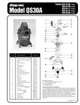
FUEL SYSTEM.
scale on
altimeter
to
"29.92" and
read pressure
altitude
on altimeter.
Be
sure
to
return
altimeter
barometric
Fuel is supplied
to the
engine
from
two tanks, one
in
each wing. With
scale to
original
barometric
setting after pressure
the fuel
selector valve on
"BOTH,
"
the
total
usable
fuel
for
all
flight
con-
altitude
has been
obtained.
ditions
is
60 gallons
for the standard tanks and 79
gallons
for
optional
long
range tanks.
Fuel
from
each
wing
tank
flows by
gravity to
a selector valve. De
-
pending upon
the setting
of
the
selector
valve,
fuel
from the
left,
right,
or both tanks flows
through
a
fuel strainer and carburetor
to the engine
induction
system.
IMPORTANT
The fuel
selector
valve should be in the
"BOTH"
position
for
take-off,
climb,
landing,
and
maneuvers
thät involve
FUEL TANK
QUICK-DRAIN
VALVE
KIT
prolonged slips
or skids.
Operation
from either
"LEFT"
or
"RIGHT"
tank
is
reserved for cruising flight.
NOTE
Two fuel tank
quick-drain
valves
and
a
fuel
sampler cup are
available
as
a kit to
facilitate
daily
draining
and
inspection
of
fuel
in
the main
tanks
When
the fuel
selector
valve
handle is in the
"BOTH"
for
the presence
of water
and
sediment. The
valves replace
existing fuel
position in
cruising
flight, unequal
fuel
flow
from each
tank
drain plugs
located
at the
lower
inboard
area
of the wing.
The
fuel
tank
may
occur if
the
wings
are not
maintained
exactly
sampler
cup,
which
may
be stowed
in the
map
compartment,
is
used
to
level.
Resulting
wing heaviness
can be alleviated
drain
the valves.
The
sampler cup
has a probe
in
the
center
of the
cup.
gradually
by turning
the selector valve handle to the
When
the probe is
inserted into
the
hole
in
the
bottom
of
the
drain valve
tank in the
"heavy"
wing.
and pushed
upward,
fuel
flows into
the
cup
to
facilitate visual
inspection
of the
fuel.
As
the
cup
is
removed, the drain
valve
seats, stopping
the
For fuel system
servicing information,
refer
to Lubrication
and
Ser-
flow
of fuel.
vicing Procedures in Section
V.
7-16
2-1

I
1.ANDING.
LEFT
FUEL
TANK
RIGHT
FUEL TANK
(1)
Before
landing,
push "WING LVLR"
control knob
full
in to the off
position.
VENT
VENT
EMERGENCY
PROCEDURES
FUEL SELECTOR
VALVE
IÎ
R
malÎünCÉiOn Should
occur,
the
system
is
easily
overpowered
with
pressure
on the control wheel.
The system should then be turned
off.
In
the
event
of
partial
or
complete vacuum
failure,
the
wing
leveler will
auto-
Ei
matically
become
inoperative.
However,
the Turn
Coordinator used
with
the
wing
leveler system will not
be
affected
by loss
of
vacuum since
it
is
designed
with
a
"back-up" system
enabling it to
operate
from either
vac-
uum
or electrical
power in the event of failure
of one of these
sources.
FUEL
SYSTEM
OPERATING
NOTES
-SCHEMATlC-
(1)
The
wing
leveler system may
be
overpowered at
any
time
without
damage
or wear. However,
for extended
periods of
maneuvering
it
may
FUEL
TO
ENGINE
#
be
desirable
to turn the
system
off.
STRAINER
ENGINE
PRIMER
(2)
It
is
recommended that the system not be engaged
during
take-off
and landing.
Although the system can
be
easily
overpowered, servo
forces
could
significantly alter
the
manual "feel" of the aileron
control, especially
should a
malfunction
occur.
THROTTLE
's....
CARBURETOR
..-
-
~'
CODE
MIXTURE
To
CONTROL
KNOB
ENGINE
FUEL
SUPPLY
VENT
MECHANICAL
LINKAGE
Figure
2-2.
2-2
7-15

WING
LEVELER
ELECTRICALSYSTEM.
I
Electrical
energy
is
supplied
by a
14-volt,
direct-current
systert
powered
by
an
engine-driven
alternator (see
figure
2-3). The
12-volt
A
wing
leveler
may
be installed to augment the
lateral stability of the
battery
is
located aft
of
the
rear cabin
wall
below the
aft baggage
floor.
airplane. The system uses the
Turn
Coordinator
for
roll
and yaw
sensing.
Power
is
supplied to all
electrical circuits
through a
split
bus
bar,
one
Vacuum pressure, from the
engine-driven
vacuum
pump,
is routed from
side
containing
electronic
system circuits
and
the
other
side
having
gen-
the
Turn Coordinator to
cylinder-piston
servo units attached
to
the aileron
eral electrical
system
circuits. Both
sides of the
bus
are
on at all
times
control system. As the airplane deviates from
a wing level
attitude,
except
when
either
an
external power source is
connected or
the
starter
vacuum pressure in the servo units is increased or relieved
as
needed
to
switch
is
turned
on;
then
a
power
contactor is
automatically
activated to
actuate the ailerons to
oppose
the deviations·
open the
circuit to
the
electronics
bus. Isolating
the
electronic circuits
in this manner
prevents harmful transient voltages
from damaging the
A
separately
mounted
push-pull
control
knob,
labeled "WING
LVLR",
transistors in
the
electronics equipment.
is
provided on the left side
of
the instrument panel
to
turn the
system on
and off. A "ROLL TRIM"
control
knob on the
Turn
Coordinator
is
used
MASTER SWITCH.
for manual roll trim control to compensate
for
asymmetrical
loading of
fuel
and passengers,
and to
optimize
system
performance
in
climb,
cruise
The
master
switch is
a
split-rocker
type
switch labeled "MASTER,
"
and
let-down·
and
is "ON"
in the up
position
and."OFF"
in
the
down position. .The right
half of the
switch,
labeled
"BAT,
"
controls
all
electrical power to the
i
OPERATING
CHECK
LIST
airplane.
The
left
half,
labeled
"ALT,"
controls
the alternator.
TAKE-OFF-
Normally,
both
sides of
the master
switch
should be used
simulta-
neously; however,
the
"BAT" side of the switch
could
be
turned "ON"
(1)
"WING
LVLR"
Control
Knob
--
Check in
off
position
(full in).
separately to check
equipment while
on
the
ground. The
"ALT" side of
the
switch,
when placed
in
the "OFF" position,
removes
the
alternator
from the electrical
system.
With
this switch in
the "OFF"
position, the
.IMB•
entire
electrical
load is
placed
on
the
battery,
and all
non-essential elec-
(1)
Adjust stabilizer and
optional rudder
trim
for climb.
trical
equipment should
be
turned off
for
the
remainder
of the
flight.
(2)
"WING LVLR" Control
Knob
--
Pull
control knob
"ON."
AMMETER.
(3)
"ROLL TRIM" Control
Knob
--
Adjust for
wings level
attitude.
The
ammeter
indicates the
flow
of
current,
in amperes,
from the
al-
ternator to the battery
or
from
the
battery to
the
aircraft
electrical
sys-
CRUISE.
tem. When the
engine is operating
and
the
master switch
is "ON,"
the
ammeter indicates
the charging
rate applied
to
the
battery.
In the
event
(1)
Adjust
power, stabilizer
and
optional rudder trim
for
level flight.
the
alternator
is
not
functioning
or
the electrical load
exceeds
the
output
(2) "ROLL TRIM"
Control
Knob
--
Adjust
as desired.
of the
alternator,
the ammeter
indicates
the
discharge rate
of
the
battery.
DESCENT.
clRCUIT BREAKERS AND FUSES.
Most
of
the
electrical
circuits in
the
airplane
are protected
by
"push-
(1)
Adjust power, stabilizer and
optional
rudder trim
for
desired
to-reset"
circuit breakers
mounted on
the
instrument panel.
Exceptions
speed and rate of descent.
to
this are the battery
contactor
closing
(external
power) circuit and
op-
(2) "ROLL TRIM" Control Knob
--
Adjust as desired.
tional clock
and flight hour
recorder circuits
which have fuses
mounted
7-14
2-3

ELECTRICAL
SYSTEM
TO OPTIONAL
TURN
CESSNA
CASTERING AXLES
SCHEMATIC
2
cooo
IANLATUORRNORND-
REGULATOR
BANK INDICATOR
TO
HEATED
PITOT
SYSTEM
CRStering
axles may be installed on the main
landing gear as
optional
ALT
PITOT HEAT
foPTI
equipment. The axles are
essentially
spring-loaded,
fluid-filled,
orifice-
F
F
TO
LANDING
dampened cylinders.
L
&
TAXI
LIGHTS
(OPT)
ALTERNATOR CIGAR
LIGHTER
In
the event of improper drift correction at
touchdown,
the
castering
ALTE
N TOR
(
IT
AK
LRL
EX1eS permit the
main wheel
on the
downwind side
of
the
airplane
to
mo-
'ER
(ort
i
mentarily
swivel
outboard
to
align
with the
drifting
ground
track
of
the
AMMETER
O I NL
CONNT HTS
airplane.
However,
the
opposite
(upwind) wheel
is
incapable
of
swiveling
COS CEROR
Av
WHEEL
MAP
LIGHT
inboard,
and it scrubs
slightly
until
the
drifting
motion has ceased. The
L
GHT5
p
IL
DILUTION
SYSTEM
net effect iS to
minimize the
lurching action
at
touchdown caused by
side-
REVERSNEACOLARRITY
GLRUG
EDCESERA
CLEE
TO
FUEL
QUANTITY
IND.
Ward
drift and
to
restore the
intended ground track during
the landing
roll.
(OPT
&
CYL.
HEAD
TEMP.
GAGE
During
ROrmal
taxi,
the
castering
axles will not swivel.
TO
COMPASS
-
& INSTRUMENT
LIGHTS
10
TO
IGNITION.STARTER
,, ,
FLIGHT HOUR
SWITCH
RECORDER
INST
py
LIGHT TO
MAP
& INSTRUMENT
SPLIT BUS
LIGHTS
(OPT)
STARTERBAT
ERY
SR
S
URHE
TA
OR
GHDOMEL
LIGHTRSTESY
CONTACTOR
|s
10
TO
FLASHING
BEACON
BATTERY
CLOCK
BCN LlGHT
STOWABLE RUDDER
PEDALS
TO RADIO
(OPT)
-
.
.
RADIO
i
A
L
TO
INSTRUMENT
TO RADIO
(OPT)
Stowable
right-hand
rudder pedals are available
as part of the
option-
c
u'i'r
_
"^°i°
2
al
right-hand
flight controls installation. The pedals fold
forward
and
BREAKER TO
RADIO
(OPT)
Stow
against
the
firewall, thereby permitting the right front passenger to
*
R^Dio 3
extend his feet
forward
for greater
comfort,
and also to rest
his
feet on
to RAoio
corry
the rudder pedals during
flight
without,
in
any
way, interfering
with the
RADIO
4 flight
operation
of
the pilot's
rudder pedals.
CODE
TO RAD10 {OPT)
CIRCUIT
BREAKER
(AUTO-RESET)
I N 10
-
RADio
5
A
puSh-pull
control
on
the instrument panel actuates
the pedal
unlock-
CIRCUIT
BREAKER (PUSH-RESET)
5W1TCH
TO
AUDIO AMPLIFIER
(OPT)
ing
mechanism. The pedals
are stowed
simply
by
squeezing
the double
FUSE
AUD AMP
buttons of the control
knob
and pulling
the knob
out to release the
pedals;
DIODE
TO
AUTOMATIC PILOT
(OPT)
the pedals can then
be pushed
forward against
the
firewall where
they
are
CAPACITOR
(NOISE
FILTER)
AUTO
PILOT
retained by spring clips
within
a
bracket. The pedals are
restored to
RESISTËR
MAGNETOS
their
operating positions by pushing the control knob
full
in,
and
inserting
the toe of
the shoe
underneath each pedal and pulling each
pedal
aft
until
it
snaps
into position.
The
pedals
are
again
ready
for flight
use by the
Figure
2-3·
right front
passenger.
2-4
7-13

NOTE
near
the
battery.
Also,
the cigar lighter
is
protected
by
a
manually-reset
type circuit
breaker mounted
directly
on
the
back of the
lighter behind the
Operation at
peak EGT is not
authorized for continuous
instrument panel.
Automatically
resetting
circuit
breakers
mounted
operation, except to establish
peak EGT for
reference
behind
the
instrument
panel protect
the
alternator field
and
wiring circuit
at 75%power or
less.
Operation
on
the lean side of
and the optional turn coordinator
or
optional
turn-and-bank
indicator
cir-
peak EGT
or
within
25°
of peak EGT is not
approved.
cuit.
The
chart
on page
7-11
should
be used
to
establish mixture settings CONTROL
WHEEL
MAP LIGHT
(OPT).
in take-off,
climb and cruise
conditions.
A map
light
may
be mounted on the bottom of the pilot's
control wheel.
The yellow
index pointer
may be set at the
reference
point,
or to
a
The light
illuminates the lower
portion
of the cabin
just
forward
of
the
specific point
to lean to.
It can be positioned
manually
by
turning
the
pilot and is helpful
when
checking maps
and
other
flight data during
night
screw adjustment
on
the
face of the
instrument.
operations.
To
operate the
light,
first
turn
the
"NAV LIGHTS"
switch
on,
then
adjust the
map
light's
intensity
with the knurled rheostat knob located
For
maximum performance
take-off,
mixture
may be set
during static
at the bottom of the
control
wheel.
full
power
run-up, if
feasible,
or
during the ground roll.
FLASHING
BEACON
(OPT).
NOTE
The flashing
beacon should not be used
when
flying
through clouds
Enrichen mixture
during climb if
excessive
cylinder or
overcast;
the
flashing
light reflected from water droplets or particles
head
temperatures occur. in the atmosphere, particularly
at
night,
can produce
vertigo
and
loss of
orientation.
In the
event
that
a
distinct
peak
is not
obtained,
use
the
correspond-
ing
maximum
EGT as the
reference
point
for
enriching
the
mixture to the
desired
cruise
setting.
CABIN
HEATING
VENTILATING AND
Changes
in altitude
or
power
setting
require
the
EGT
to
be
rechecked.
Mixture may
be controlled
in cruise
descent by
simply enriching to
avoid
DEFRO
ST
INGSYSTE
M.
engine
roughness.
During
prolonged
descents,
maintain sufficient power
to
keep the EGT needle on
scale.
In idle
descents or
landing approaches
The temperature and volume of
airflow
into the cabin
can
be
regu-
use full rich mixture. For
idle descents
or landing
approaches
at high
lated
to any
degree desired
by manipulation of the
push-pull
"CABIN
elevations,
the
mixture
control
may
be set
in
a
position to
permit smooth
HEAT"
and
"CABIN AIR" knobs.
engine acceleration to
maximum
power.
NOTE
Always pull out
the
"CABIN AIR"
knob
slightly
when
the
"CABIN
HEAT"
knob
is out.
This
action increases
the
airflow
through the
system,
increasing efficiency,
and
blends
cool
outside air
with
the
exhaust
manifold heated
air,
thus eliminating the
possibility
of
overheating
the
system
ducting.
Front cabin
heat
and
ventilating
air is supplied by
outlet
holes spaced
across
a
cabin
manifold
just
forward
of the
pilot's and copilot's feet.
Rear
7-12
2-5

cabin
heat
and
air is
supplied by two
ducts
from
the
manifold, one
extend-
ing down
each.side of
the
cabin to an
outlet
at the front
door post
at floor
CESSNA
ECONOMY
MIXTURE
INDICATOR
level.
Windshield defrost air is
also
supplied
by
a
duct
leading
from
the
cabin manifold.
The Cessna
Economy
Mixture
Indicator
is an exhaust gas
temperature
Separate
adjustable ventilators
supply
additional air; one
near each
(EGT)
sensing
device
which
visually
aids
the
pilot
in
obtaining
either
an
upper corner
of
the
windshield
supplies air
for
the
pilot and
copilot,
and
efficient
maximum power mixture
or a
desired cruise mixture.
Exhaust
two
in the rear
cabin
ceiling supply
air to
the
rear seat
passengers.
gas
temperature varies with cylinder
fuel-to-air
ratio,
power,
and RPM.
OPERATING INSTRUCTIONS.
REMOVAME CABlN DOOR.
The
reference
EGT
must
be known before the EGT indicator can
be
used
for
take-off
and
climb. Determine the reference
EGT
periodically
The right cabin door has removable
hinge
pins
and a
detachable
door
as
follows:
ritop
permitting door removal
when large
or
bulky cargo must be
loaded.
(1)
Establish
65%
power in level flight
at
2450
RPM and part throttle.
AFT BAGGAGE COMPARTMENT.
(2)
CarefullyleantopeakEGT. ThisisthereferenceEGT.
An
aft baggage
compartment
is
provided
just
back of the
rear cabin
wall and is
accessible
by
taking
off the
quick-removable
wall panel. The
compartment is
useful
for
storing
utility
type seating
when
large cargo is
FLIGHT POWER
EGT REMARKS
to be
carried in
the cabin area. Also,
it
provides an extra
storage
space
coNDITION
SETTING
for
light,
but
bulky
articles. A total of 50
pounds of baggage or
cargo
may
be carried
in
this area. Four
tie-down
rings and a
baggage
net are
TAKE-OFF
Full throttle
200°
richer than Use
FULL RICH mixture
used to tie down the
baggage.
Weight and
balance
data and
illustrations
AND CLIMB
and
2600
RPM
REFERENCE EGT
below
3000'
of the
compartment
may
be
found in
Section
IV.
NORMAL
23"
MP
and
125°
richer than
Above
10.000' use
CLIMB
2450 RPM
REFERENCE
EGT
.
BEST
POWER mixture
STARTING
ENGINE.
BEST POWER
mixture,
MAXIMUM
CRUISE
Peak minus
125°
F
1
MPH TAS increase and
Ordinarily
the
engine starts
easily
with one or two
strokes of
the
SPEED
75% or less
(ENRICHEN)
10% range loss
from
primer
in
warm temperatures to six strokes
in
cold
weather,
with
the
NORMAL
LEAN
throttle
open approximately
1/2
inch.
In
extremely
cold
temperatures,
it may
be
necessary
to
continue priming
while cranking.
Weak
inter-
NORMAL
Peak minus
75°
NORMAL LEAN
mixture-
mittent
firing
followed by
puffs
of
black
smoke
from
the
exhaust
stack
CRUISE
75%
or less
(ENRICHEN)
Owner's
Manual and Power
indicate overpriming
or
flooding.
Excess
fuel can be cleared from the
Computer performance
combustion chambers by the
following
procedure:
Set
the mixture
control
full
lean and
the throttle
full
open; then crank the engine
through
several
MAXIMUM
Peak
minus
25°
2 MPH TAS
loss
and
10%
revolutions
with the
starter. Repeat the
starting
procedure without
any
RANGE
65%
or
less
(ENRICHEN)
raOnge iner
sAeNfrom
additional
priming.
2-6
7-11

AMBIENT FILLING
AMBIENT
FILLING
If
the
engine is
underprimed
(most
likely
in
cold
weathefwith a
cold
TEMPERATURE
PRESSURE TEMPERATURE
PRESSURE
engine),
it will not
fire at all.
Additional
priming will
be necessary
for
°F
PSIG
°F
PSIG
the
next
starting
attempt.
As soon as the
cylinders begin to fire, open
the
throttle slightly to
0
1600
50
1825
keep
it
running.
10
1650
60
1875
20
1700
70
1925
If
prolonged cranking
is
necessary,
allow
the starter motor
to cool
30
1725
80
1975
at frequent
intervals,
since excessive heat
may
damage the
armature.
40 1775
90
2000
cubic feet
of oxygen, under
a pressure
of 1800
psi
at
70°F.
Filling
pres-
TAXIING.
sures
will vary,
however, due to the
ambient
temperature
in the
filling
area, and because of the
temperature
rise
resulting
from
compression of
The carburetor air heat
knob
should
be
pushed full in
during
all
the
oxygen. Because of
this,
merely filling to 1800
psi will not
result in
ground operations unless
heat is
absolutely necessary
for smooth
engine
a
properly
filled cylinder.
Fill to
the pressures
indicated
in table above
operation. When the
knob is
pulled out
to the
heat
position,
air
entering
for
the
ambient temperature.
the engine
is not filtered.
IMPORTANT
Taxiing
over
loose
gravel
or cinders
should
be done
at low engine
speed
to avoid abrasion
and stone
damage
to
the
propeller tips.
Oil,
grease, or
other
lubricants in contact
with oxygen
create
a
serious fire
hazard,
and such
contact
must be
avoided
when
handling
oxygen equipment.
BEFORE
TAKE-OFF.
Since
the
engine is
closely
cowled for
efficient
in-flight
cooling,
precautions
should
be
taken to avoid
overheating
on
the ground.
Full
throttle checks
on
the ground are not
recommended
unless the pilot has
good reason
to
suspect
that
the
engine is
not turning
up properly.
The magneto
check
should
be
made
at
1700
RPM with the propeller
in flat pitch
as follows:
Move
the
ignition
switch
first to
"R"
position
and note
RPM.
Then move
switch
back to
"BOTH"
position
to
clear
the
other set
of plugs.
Then move
switch to "L"
position and note RPM.
The difference between the
two
magnetos operated
singly
should
not
be
more
than
50
RPM. If there is
a
doubt
concerning
the operation
of the
ignition
system,
RPM checks
at a
higher engine
speed
will
usually
con-
firm
whether
a deficiency exists.
An absence
of
RPM drop may be
an
indication
of faulty grounding of
one
side
of
the
ignition system or
should be cause
for
suspicion
that
the
magneto
timing is
set in
advance
of
the
setting
specified.
7-10
2-7

Prior
to flights
where
verification
of proper
alternator and
voltage
(6)
Unplug the
delivery
hose from
the outlet
coupling when
discontin-
regulator
operation
is
essential
(such as
night or instrument
flights),
uing
use
of the oxygen
system.
This
automatically
stops the
flow of
a positive verification
can
be made
by
loading
the electrical system
oxygen.
momentarily
(3
to 5
seconds)
with
the optional
landing
light (if so
equîp-
(7)
Position oxygen supply
control
knob
"OFF.
"
ped)
during the engine run-up (1700
RPM). The ammeter will
remain
within
a
needle
width of
zero if
the
alternator and
voltage
regulator
are
operatingproperly·
OXYGEN
DURATION
CALCULATION.
The
Oxygen
Duration Chart
(figure
7-3)
should be used in
determin-
TAKE-OFF.
ing the usable
duration (in
hours)
of the
oxygen
supply in your
airplane.
The
following
procedure outlines
the
method
of
finding
the
duration
from
It
is
important
to check
full-throttle
engine
operation early in the
the
chart.
take-off
run. Any signs
of
rough
engine
operation
or
sluggish
engine
acceleration
is
good
cause for
discontinuing
the
take-off.
(1) Note
the available oxygen
pressure
shown on the
pressure
gage.
(2) Locate this pressure
on
the
scale on the left side
of
the
chart,
Full
throttle
runups
over loose
gravel
are especially harmful
to
then
go across the chart
horizontally
to the right
until
you intersect
the propeller
tips
and
stabilizer
leading edge.
When
take-offs
must
be
the line
representing
the
number
of
persons
making
the
flight.
After
made over
a
gravel
surface,
it is very important
that
the
throttle
be
intersecting
the
line,
drop down
vertically to the
bottom
of the
chart
advanced
slowly.
This
allows
the
airplane to
start
rolling
before
high
and read
the
duration
in
hours given
on
the
scale.
RPM is
developed,
and the
gravel will
be blown back
of
the
propeller
(3)
As
an
example of the
above
procedure, 1400
psi
of pressure
will
rather than
pulled
into it.
safely sustain the pilot
only for
nearly 6
hours
and 15
minutes.
The
same pressure
will sustain the
pilot
and three
passengers
for
approxi-
Most engine wear occurs
from improper operation
before
the
engine
mately 2 hours
and
30
minutes.
is up
to normal operating
temperatures,
and operating at
high power and
RPM's. For this
reason,
the use
of maximum power for
take-off
should
NOTE
be
limited
to that
absolutely
necessary for
safety.
Whenever possible,
reduce
take-off
power to
normal
climb power.
The
Oxygen Duration
Chart
is based
on
a
standard
con-
figuration
oxygen
system
having
one orange
color-coded
Normal
take-offs
are
accomplished
with
wing
flaps up,
cowl flaps
hose
assembly
for the
pilot and
green
color-coded
hoses
open,
full
throttle,
and
2600
RPM. Reduce
power
to
23 inches of
mani-
for the
passengers.
If
orange
color-coded
hoses
are
fold pressure and
2450 RPM
as soon
as practical
to
minimize engine
provided
for pilot and
passengers,
it
will
be
necessary
wear.
to compute new oxygen
duration
figures
due
to
the
greater
consumption of oxygen
with these
hoses. This
is
accom-
Using
20°
wing
flaps
reduces
the total distance
over
an
obstacle by
plished by
computing the
total
duration available
to
the
approximately
20
per
cent.
Soft
field
take-offs
are
performed with
20°
pilot
only
(from
"PILOT
ONLY" line
on
chart),
then
di-
flaps by
lifting the airplane
off
the
ground as
soon as
practical
in
a
slight-
viding
this
duration
by
the
number
of persons (pilot
and
ly
tail-low
attitude. However,
the
airplane
should be
leveled
off
immedi-
passengers)
using oxygen.
ately to accelerate
to a
safe
climb speed.
If
20°
wing flaps
are used
for
take-off,
they
should be
left down until
all obstacles
are
cleared.
To
clear
an
obstacle with
wing
flaps
20°,
a
OX YGEN
SYST
EMSERV I
CI
NG.
61
MPH climb speed should be
used.
If no obstructions
are
ahead, a
best
"flaps
up"
rate-of-climb
speed
(95
MPH) would
be
most
efficient.
These
The oxygen
cylinder,
when
fully
charged, contains
approximately
48
2-8
7-9
/